Separately charging all four cells from the Baofeng BL-5 packs covered the Electronics Bench with wires:

The cell sits on a ceramic tile as a nod to fire safety, although I doubt it makes any difference.
The discharge tests showed two nearly identical pairs:

Surprisingly, cells A and B (upper traces) were deaders in the original packs. Cells C and D (lower traces) were more-or-less fully charged, but now have a lower terminal voltage and slightly lower capacity. I have no explanation for that, nor for the voltage undulations.
The rebuilt packs pair up A+B and C+D.
Reassembling pairs into the pack shell and resoldering all the leads produces a good pack:

I later added a snippet of heavy manila paper under the nickel tape bent around the edge of the pack as a third level of insulation, in the interest of having the nickel tape not produce a dead short between the isolated – terminal and the + cell case.
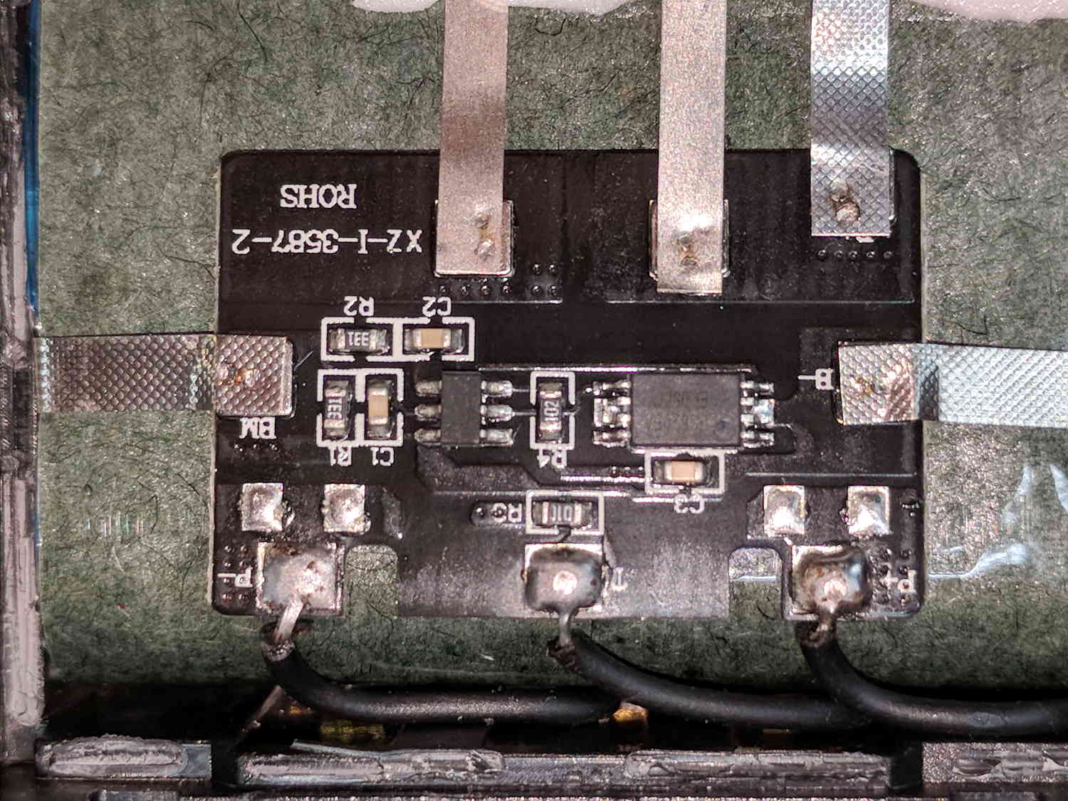
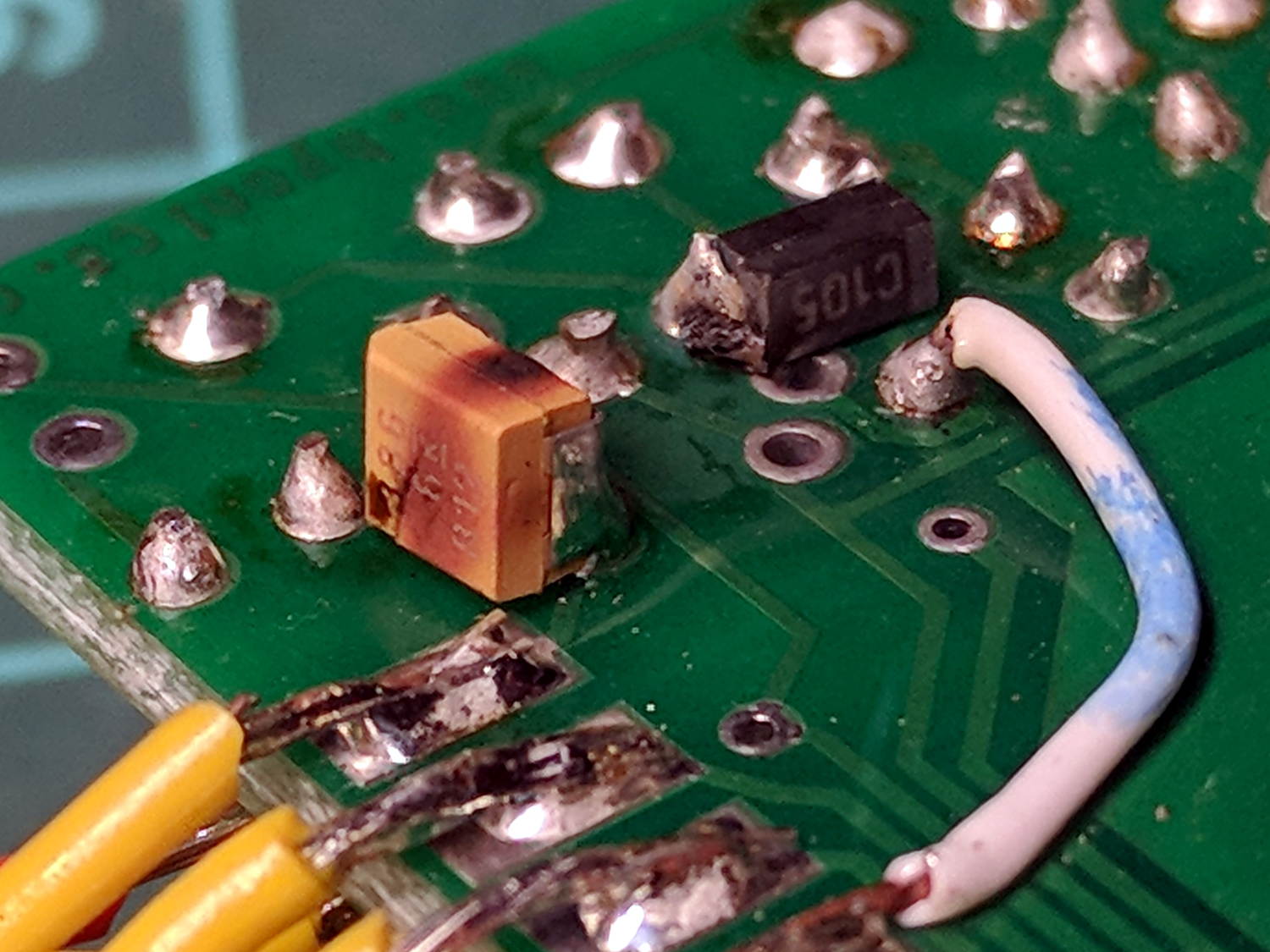
Memo to Self: tape the long wiggly leads from the protection PCB to the radio contacts (at the left side) before soldering the PCB to the cell terminals, because an inadvertent short will convert the 8205A battery protection IC into a Light-Emitting IC, at least for a moment, and subsequently release the Acrid Smell of Electrical Death. A handful of charge PCBs are en route halfway around the planet, from which I intend to liberate one IC for this board; with luck, I didn’t incinerate anything else.
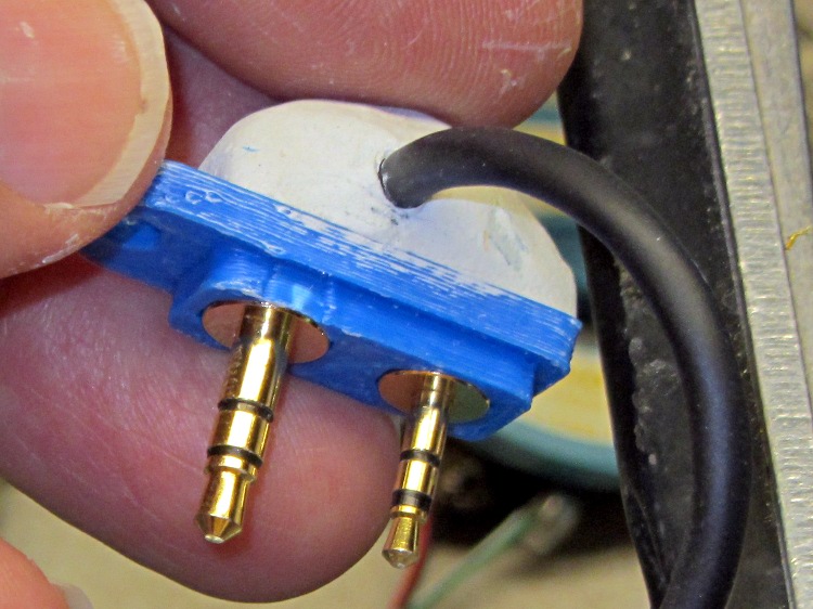
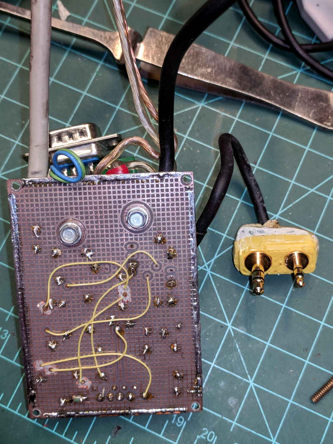
The pack works fine in the radio, as does the APRS interface:

Unfortunately, two APRS iGates vanished in the last year, leaving poor coverage south of Poughkeepsie.