Ed Nisley's Blog: Shop notes, electronics, firmware, machinery, 3D printing, laser cuttery, and curiosities. Contents: 100% human thinking, 0% AI slop.
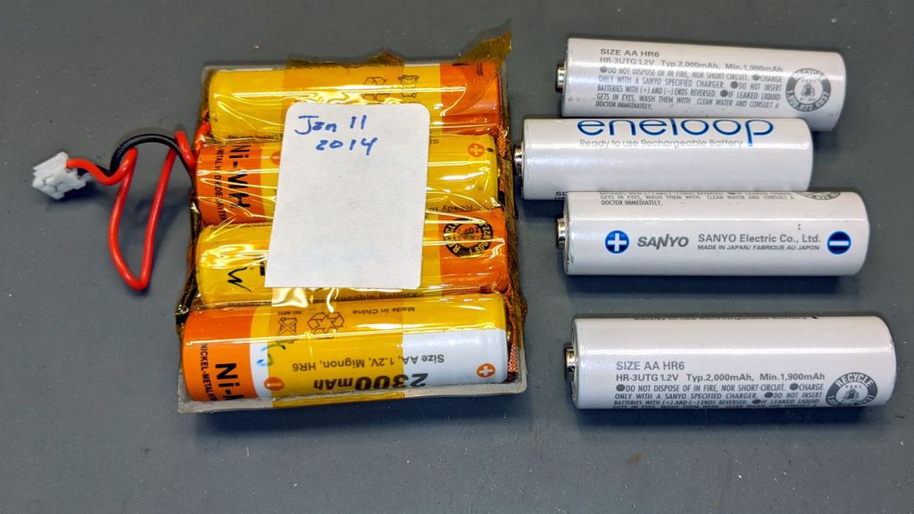
My old Aceco FC1002 frequency meter stopped working without being plugged into the charger. It runs from a quartet of NiMH cells taped into a tray I made seven years ago:
The faceplate bears the scars of its cracked acrylic (?) coating, so I pushed it out, traced the outline on a flat piece of polypropylene clamshell packaging, cut it out, and stuck it in place with tapeless sticky:
Aceco FC1002 – polypropylene faceplate
That removes the branding, but IMO improves the appearance.
It should continue working for another half decade or so!
We recently installed a Dripworks drip irrigation system for Mary’s garden and, of course, pre-assembled the emitter / dripline tubing, fittings, and supply / filter / plumbing for each of the beds in the Basement Shop. A few days after burying the main lines, plumbing the filter + pressure regulator, and plugging in half a dozen bed assemblies, Mary noticed some emitter tubes weren’t delivering any water and other beds seemed too dry.
N.B.: We bought everything directly from Dripworks. This is not counterfeit crap from a sketchy Amazon seller.
I cut the dripline just downstream of the Micro-Flowvalve on a completely dry bed, whereupon no water emerged. Cutting the supply tube just upstream of the valve produced a jet squirting halfway along the bed. I tried and failed to blow air through the valve: it was completely blocked despite being in the “open” position. I installed another valve and the emitter tube started working properly.
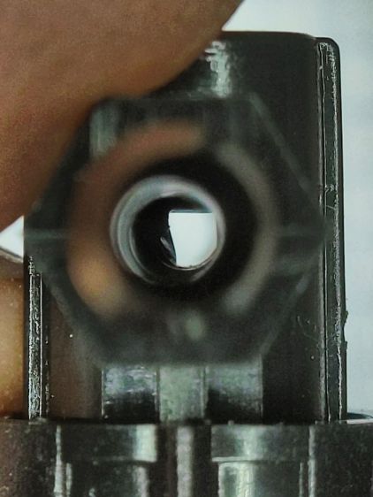
I sat down at the kitchen table with a bag of unused valves and peered through them (the pix are through the microscope):
Dripworks valve – mostly open lumen
That’s one of the better-looking valves, with only a little mold flash in the lumen.
Partially occluded lumens were more typical:
Dripworks valve – partially occluded lumen
Quite a few were almost completely obstructed:
Dripworks valve – mostly occluded lumen
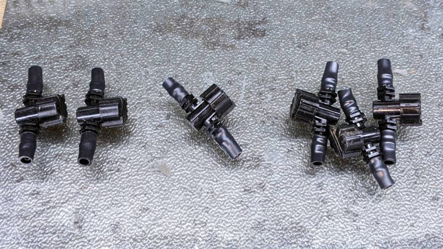
For lack of better instrumentation, I blew through the valves and sorted them by effort:
Dripworks valve – sorted by blockage
Two of the valves in the group on the left are completely blocked, with the others mostly blocked.
The middle group has enough mold flash to produce noticeable resistance to the air flow. I think water would have more trouble getting through, but the emitters would at least look like they’re delivering water.
The group on the right has mostly unblocked valves, with visible mold flash but little restriction.
I have no way to measure the actual water flow, so it’s entirely possible the QC spec allows considerable blockage while still delivering enough water to the emitters. More likely, the spec assumes a clear lumen and the mold flash is a total QC faceplant; it’s obviously not a controlled quantity.
Well, I can fix that:
Dripworks valve – drilling
That’s a 2.3 mm drill going straight through the valve body. I drilled the valves from both ends and blew out the swarf:
Dripworks valve – drill swarf
That produced twenty valves with clear lumens. Of course, the drill leaves a slightly rough interior surface, but it’s now much easier to blow air through them.
We hadn’t installed the driplines in two beds with three emitter tubes per bed. I cut out those six unused valves and sorted them by resistance:
Dripworks valve – six samples
Both of the valves on the left are blocked, the three on the right are mostly OK, and the one in the middle is partially blocked.
With two dozen repaired valves in hand, we returned to the garden, I cut 22 valves out of the installed driplines and replaced them under field conditions. Returning to the Basement Laboratory, I blew the water out (*), sorted them by resistance, and produced a similar distribution, albeit with no pictorial evidence. Although we have no immediate need for the used valves, they’re drilled out and ready for use.
In very round numbers, you should expect:
A third of Dripworks valves will pass (close to) the expected flow
A third will have a minor flow restriction
A quarter will have a severe flow restriction
One valve in ten will be completely blocked
Plan to drill out all the Micro-Flow valves before you assemble your driplines.
AFAICT, none of the other ¼ inch fittings we used have any interior flash, so it’s only a problem with the valves.
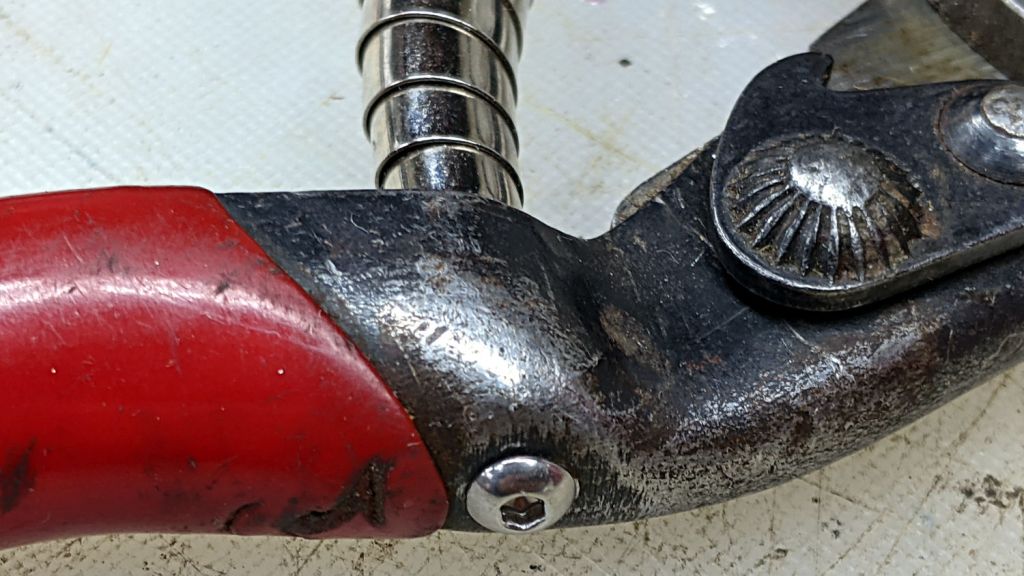
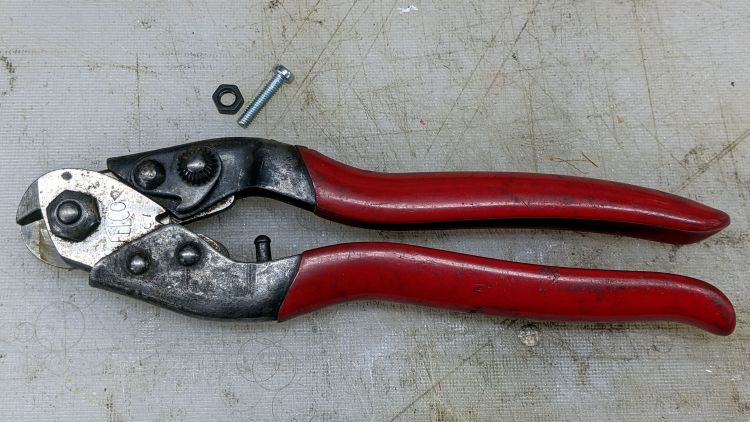
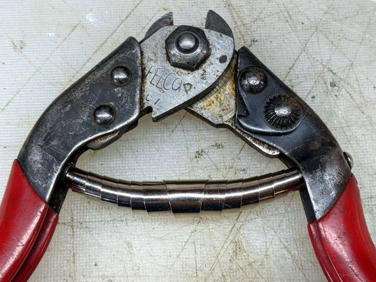
The back of the Pliers & Cutters drawer produced an ancient Felco C7 Cable Cutter minus its spring:
Felco C7 cutter – missing spring pin
That’s an M4 screw serving as a size test for the hole where the other pin used to be.
Surprisingly, Felco still exists, still makes the C7 Cable Cutter, and actually sells a replacement spring as part number C7/10. Unfortunately, their online sales apparatus and cart seem broken: I put the spring in the cart, but found no way to pay for it. Worryingly, the usual Terms & Conditions link produced a modal dialog with one word: TEST.
So I got a spring (part number 5/11, available only as a pair in kit 5/91) for a Felco C3 cutter (no, the numbers do not match) from Amazon. Later I found a sketchy seller offering a sketchy C7/10 spring that might fit correctly or could be total trash.
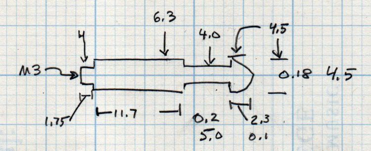
Felco swaged the original spring pins into the handle, a manufacturing technique I certainly cannot duplicate, but an M3 screw will just barely fit inside a 4 mm stud, so I made some measurements:
Felco replacement spring pin – dimension doodle
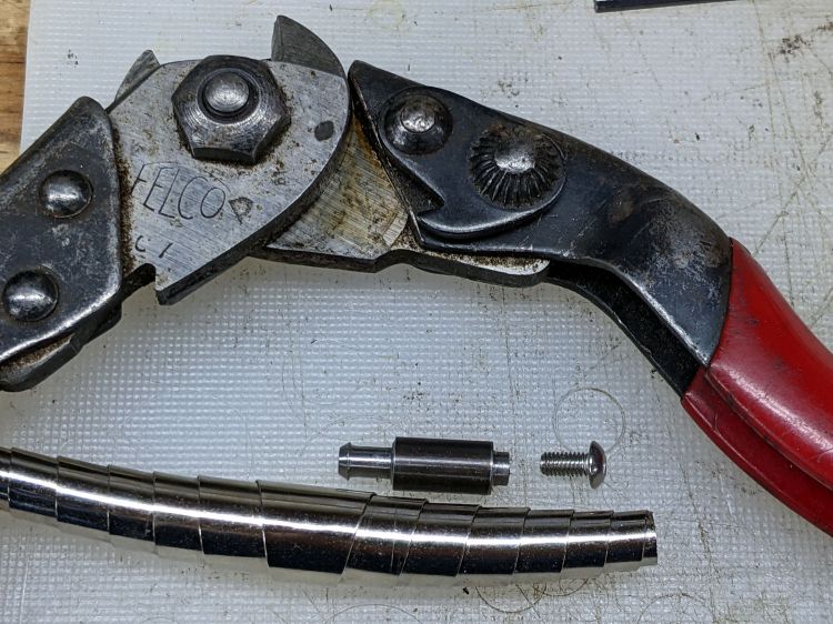
Fitting action to words:
Felco C7 cutter – replacement spring pin
That started as a 1/4 inch rod of no particular provenance and is reasonably close to the actual dimensions.
The spigot on the screw end is threaded M3 and is just barely shorter than the thickness of the handle, so the button-head screw can pull it snug:
Felco C7 cutter – button screw
And then the spring just snapped into place:
Felco C7 cutter – spring installed
It it obviously grossly excessively too long, but that really doesn’t matter for the number of power-on hours it’s likely to see during my administration. In truth, it feels pretty good in the hand after releasing the latch and having it expand smoothly.
If I ever run across a C7/10 spring, it’ll be an easy swap.
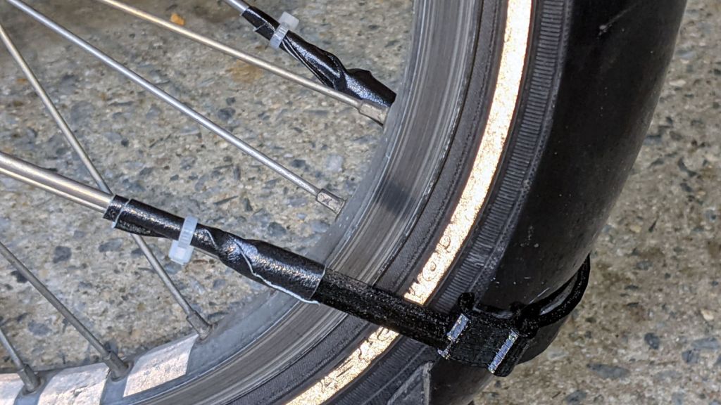
The front fender on Mary’s bike suffers a bit more stress than you might expect, as she must wheel it through high grass to her Vassar Farms garden plot and the low-hanging spray flap can snag on the taller greenery.
Re-slicing the original model, printing the result, and installing it took about an hour:
Tour Easy front fender bracket – installed
Affixing the strut with duct tape and a cable tie looks déclassé, but continues to work better than anything else I’ve tried: simple, flexible, easily readjusted, totally nonfussy.
At least I now use black outdoor-rated double-stick foam tape, so life is increasingly good …
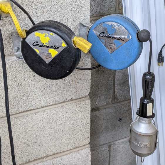
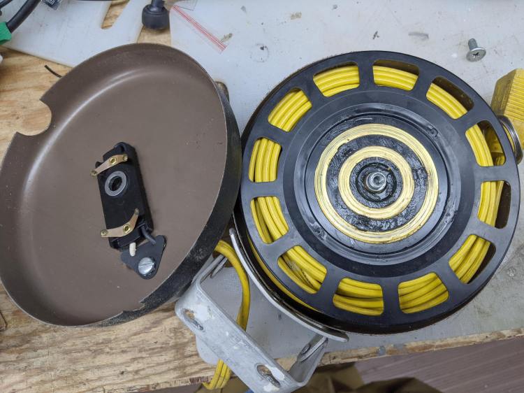
A pair of antique collectible Cordomatic reels get occasional use in the Basement Laboratory:
Cordomatic 500P reel – installed
The extension cord reel didn’t latch reliably when needed, so …
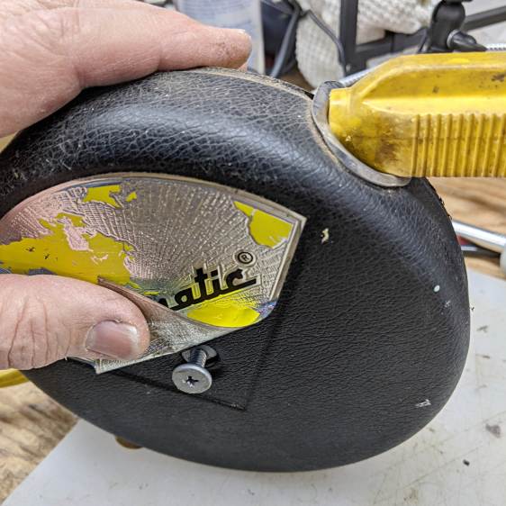
There’s an obvious screw on the other side and a non-obvious screw hidden in the obvious place:
Cordomatic 500P reel – hidden screw
The electrical contacts were in good shape, although I smeared the grease around the rings just to make it seem like I did something:
Cordomatic 500P reel – contacts
The ratchet pawls hide under a riveted cover:
Cordomatic 500P reel – pawl cover
The duct tape shows I’d been in there once before, likely for the same problem, and had already drilled out the rivets.
Alas, I forgot to take a picture after removing the cover, but the general idea is to put just a dot of oil on the pivots (which, as you’d expect, are the rivets), wiggle everything around, and reassemble in reverse order.
It’ll surely work long enough that I can forget I was in there twice before …
All the work on Mary’s bike reminded me of the rear fender bracket I meant to install on mine, with more clearance for the strut stabilizing the under-seat packs:
Tour Easy Rear Fender Bracket – long setback – solid model – show
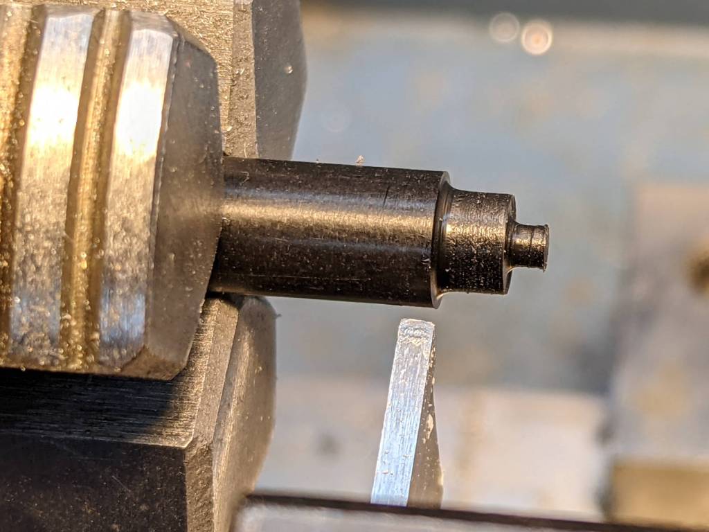
Rather than glue a PETG filament snippet into a screw, I turned a little Delrin plug:
Tour Easy Rear Fender Bracket – screw insert
It’s ready for installation when I’m willing to put the bike up on the rack and pull the rear wheel:
Tour Easy Rear Fender Bracket – screw detail
That’s actually the second iteration for the screw, as the first suffered a lethal encounter with the Greater Shopvac. I know exactly where it is, but I’m not going there …
This happened while switching from natural to black PETG:
M2 nozzle clog – exterior
A closer look:
M2 nozzle clog – exterior detail
Those pix happened after trying to extract whatever-it-is with tweezers, so it’s definitely something with a higher melting point than PETG.
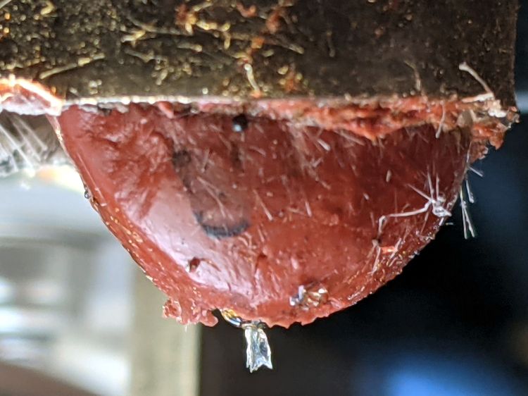
Removing the (warm) nozzle with the block held in a vise reveals a tuft of something:
M2 nozzle clog – interior
The tuft accumulated several turns while unthreading the nozzle from the hot end.
Heating the nozzle a bit more released the tuft:
M2 nozzle clog – extracted tuft
The black-to-clear transition tailing off at the bottom came from the PETG around the tuft in the cone-shaped end of the nozzle above the aperture. The 100 mil squares suggest the tuft was a distinct entity, rather than a collection of threads, and might have been over 5 mm long.
Perhaps a fragment of PTFE or another high-melting-point plastic?
Reassemble in reverse order, reset the nozzle to Z=0 on the platform, and it’s all good.