The Smell of Molten Projects in the Morning

Ed Nisley's Blog: Shop notes, electronics, firmware, machinery, 3D printing, laser cuttery, and curiosities. Contents: 100% human thinking, 0% AI slop.

Tag: Repairs

If it used to work, it can work again

  • Improved Lipstick and Lip Balm Holder With Text

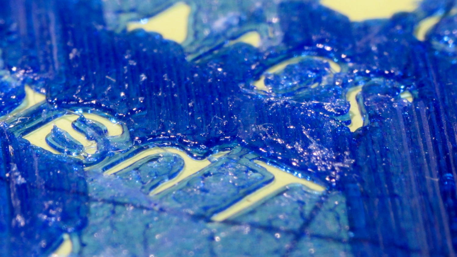
    For reasons that aren’t relevant here, Mary asked me to make four sets of improved lipstick / lip balm / sunscreen holders with five smaller tubes plus the central one and an inscription on the bottom. I ran off one with the last of the cyan PETG and the other three in natural PETG:

    Improved Lipstick Holder - on platform
    Improved Lipstick Holder – on platform

    I embossed the text into the bottom three layers. The tiny spots of detached infill for lowercase letters like a didn’t adhere to the platform, mostly because the retraction settings that work well for larger areas don’t push enough plastic out to bond with the platform before retracting and moving away.

    The bridging layer over the text shows Slic3r doing the best it can (clicky for more far more dots). Laying a uniform patch over all the letters in one shot would work better, but I don’t know how you’d define an algorithm that specifies when such a situation occurs:

    Lip Balm Holder - text bridge layer - Slic3r preview
    Lip Balm Holder – text bridge layer – Slic3r preview

    The solid infill layer directly over the Hilbert Curve bottom layer came out grossly severely excessively overstuffed, to the extent that the accumulation reduced the flow of molten plastic and caused the filament drive to strip:

    Overfilled layer 2
    Overfilled layer 2

    Previewing the G-Code show nothing out of the ordinary and, after considerable flailing around, I finally set Slic3r to begin the 3D Honeycomb infill directly atop the Hilbert Curve bottom layer. That provided enough open space to complete the mission, but more debugging was in order.

    The OpenSCAD source code as a GitHub gist:

    // Lipstick and Balm Tube Holder
    // Ed Nisley KE4ZNU – February 2016
    //- Extrusion parameters – must match reality!
    ThreadThick = 0.25;
    ThreadWidth = 0.40;
    function IntegerMultiple(Size,Unit) = Unit * ceil(Size / Unit);
    Protrusion = 0.1;
    HoleWindage = 0.2;
    //——
    // Dimensions
    RawDia = [27,18,16,18,16,18]; // actual tube diameters in desired order, center = largest first
    NumTubes = len(RawDia);
    Clearance = 2.0;
    TubeDia = [for (i=[0:NumTubes-1]) (RawDia[i] + Clearance)]; // actual tube diameters
    TubeRad = TubeDia / 2;
    echo(str("NumTubes: ",NumTubes));
    Wall = 2.0;
    BaseThick = 2.0;
    BaseFactor = 2.0;
    NumSides = 12*4;
    // per-tube info, first element forced to 0 to make entries match RawDia vector indexes
    Radius = [0, for (i=[1:NumTubes-1]) (TubeRad[0] + TubeRad[i] + Wall)]; // Tube[i] distance to center point
    echo(str("Radius: ",Radius));
    CtrToCtr = [0, for (i=[1:NumTubes-2]) (TubeRad[i] + TubeRad[i+1] + Wall)]; // Tube[i] distance to Tube[i+1]
    echo(str("CtrToCtr: ",CtrToCtr));
    Angle = [0, for (i=[1:NumTubes-2]) acos((pow(Radius[i],2) + pow(Radius[i+1],2) – pow(CtrToCtr[i],2)) / (2 * Radius[i] * Radius[i+1]))];
    echo(str("Angle: ",Angle));
    TotalAngle = sumv(Angle,len(Angle)-1);
    echo(str("TotalAngle: ",TotalAngle));
    //———————-
    // Useful routines
    // vector sum cribbed from doc
    function sumv(v,i,s=0) = (i==s ? v[i] : v[i] + sumv(v,i-1,s));
    //———————-
    //- Build it
    difference() {
    union() {
    for (i=[0:NumTubes-1])
    rotate(90 – TotalAngle/2 + sumv(Angle, (i>0) ? (i-1) : 0))
    translate([Radius[i],0,0]) {
    resize([0,0,2*BaseThick]) // bases
    difference() {
    sphere(r=BaseFactor*TubeRad[i],$fn=NumSides);
    translate([0,0,-BaseFactor*TubeDia[i]])
    cube(2*BaseFactor*TubeDia[i],center=true);
    }
    difference() { // tubes
    cylinder(r=TubeRad[i] + Wall,h=1.5*TubeDia[i] + BaseThick,$fn=NumSides);
    cylinder(d=TubeDia[i],h=1.5*TubeDia[i] + BaseThick + Protrusion,$fn=NumSides);
    }
    }
    for (i=[1:NumTubes-2]) // gap plugs
    rotate(90 – TotalAngle/2 + sumv(Angle,i-1) + (Angle[i])/2)
    translate([(TubeRad[0] + Wall),0,0])
    cylinder(r=2*Wall,h=1.5*min(TubeDia[i],TubeDia[i+1]) + BaseThick,$fn=3);
    }
    translate([0,0,-Protrusion]) // text
    mirror([1,0,0])
    linear_extrude(height=3*ThreadThick + Protrusion) {
    translate([0,25,0])
    text(text="Linda",size=7,spacing=1.05,font="Arial:style=Bold Italic",halign="center");
    translate([0,15,0])
    text(text="FDQ ExComm",size=5,spacing=1.05,font="Arial:style=Regular",halign="center");
    translate([0,7,0])
    text(text="2014 – 2016",size=5,spacing=1.05,font="Arial:style=Regular",halign="center");
    translate([0,-3,0])
    text(text="Thank you!",size=6,spacing=1.05,font="Arial:style=Regular",halign="center");
    translate([0,-15,0])
    text(text="Mary Nisley",size=7,spacing=1.10,font="ITC Zapf Chancery:style=Medium Italic",halign="center");
    }
    }
  • Vacuum Tube LEDs: Another Knockoff Neopixel Failure

    The WS2812B controller in this knockoff Neopixel failed:

    Failed W2812B Ersatz Neopixel
    Failed W2812B Ersatz Neopixel

    It used to live in the Noval socket:

    Noval socket - red phase
    Noval socket – red phase

    As with the one atop the big incandescent bulb, it failed by emitting random flashes of primary colors. This time, the Octal and Duodecar sockets were downstream and I got to watch four randomly flashing RGB LEDs, which says the controller failed enough to corrupt the data stream, but not enough to make the downstream controllers regard it as completely invalid.

    I replaced it with another one, just like the other ones, and it’s been running happily ever since.

    Fairly obviously, cheap knockoff Neopixels aren’t a good deal; the strip and these PCB versions have racked up three or four (I’m losing track) out of less than a dozen deployed. I won’t hold the overtemperature failures against the strip versions, but, still …

  • Refrigerator Trim Tab: Now With Inserts

    If the only tool you have is a knurled brass insert, well, then, you use ’em everywhere:

    Refrigerator Trim - melt-installed inserts
    Refrigerator Trim – melt-installed inserts

    Those are mounting holes for the little trim tab that closes one of the two holes left for the door hinge bracket on the vent grill of our refrigerator. The tab originally had a pair of the flimsiest little plastic pegs you’ve ever seen, both of which broke off and got themselves repaired with epoxy at least once along the way.

    The holes in the bosses started out only slightly larger than the 4-40 insert body diameter, so they were surely undersized, and the knurls definitely stretched the plastic on the way in. I applied a soldering iron to the studs until the plastic melted around the knurls, relieved much of the stretching, and secured those puppies forevermore.

    I was willing to try heat-setting them because I absolutely didn’t care if they came out a little crosseyed. For future reference, the inserts will cant off-axis unless they’re held in place: use a drill press or something similar as an alignment fixture. That would be awkward with three feet of grill hanging off the drill press table.

    I step-drilled (to avoid grabbing the soft plastic) the tab with slightly oversized 1/8 inch holes to allow some adjustment for best fit. A trial assembly showed a pair of greatly oversized 6-32 nylon standoffs spaced it well enough from the bosses for my simple needs:

    Refrigerator Trim - trial fit
    Refrigerator Trim – trial fit

    The two broken pegs sit disconsolately atop the tab, with the crushed section of their ribs showing their depth of insertion in the bosses. Note that the tab sits proud of the grill, originally supported entirely by the pegs and stopped by the square block in the middle, with no support or alignment on any side.

    The left peg popped out of its epoxy blob, forcing me to file the blob flat before drilling through both it and the tab.

    After some wiggle-n-jiggle adjustment, the tab lined up a bit better, I defined it to be Good Enough, and popped the grill back in place on the refrigerator.

    Done!

  • Refrigerator Drawer Strut Tab: Now With Inserts

    A spate of cleaning put the little tab that fixed the never-sufficiently-to-be-damned strut supporting the lower refrigerator drawers into my hands:

    Refrigerator Drawer Strut - new tab in place
    Refrigerator Drawer Strut – new tab in place

    I discovered that 4-40 knurled inserts perfectly match the available space, so I drilled the 3D printed holes out to 11/16 inch (the OD of the smaller knurls) and rammed the inserts into place:

    Refrigerator Drawer Strut Tab - knurled inserts
    Refrigerator Drawer Strut Tab – knurled inserts

    No epoxy, no heat, nothing but a friction fit.

    Looks much better, ought to work just as well, and will definitely outlive the refrigerator; if I never take that thing apart again, it’ll be fine with me.

  • Kenmore 158.17032: Mystery Spring

    This steel strip emerged from inside the arm of the Kenmore 158.17032 sewing machine that we’ve been reconditioning for one of Mary’s friends:

    Kenmore 158.17032 - mystery spring
    Kenmore 158.17032 – mystery spring

    The ends show the granular fracture of hard steel:

    Kenmore 158.17032 - mystery spring - end view
    Kenmore 158.17032 – mystery spring – end view

    It’s 13.3 mm long, 1.0 mm thick, tapers slightly from 2.8 mm on the end that once said “Japan” to 2.76 mm on the other, and that’s all we know about it.

    The sewing machine seems to work well enough without it (after some clean-and-lube action) and we haven’t found where the piece came from, but circumstantial evidence suggests it’s part of a spring somewhere inside the arm. It’s in a little bag with all the other random sewing machine parts I’ve collected along the way; perhaps some day we’ll know more and I can fabricate a replacement.

  • Kenmore 158.17032 Handwheel Clutch Disassembly

    One of Mary’s friends asked us to take a look at her Kenmore 158.17032 sewing machine that suffered from a Showstopper Problem: the handwheel turned the main shaft, but the motor pulley spun freely. You could rev the motor to maximum speed without budging the shaft, which suggested something was wrong with the clutch joining the handwheel and the belt pulley to the main shaft. This being a slightly newer model than the others in our stable, I was mildly surprised to find a completely different clutch mechanism between the drive belt and the main shaft.

    The plastic cover plate in the handwheel yielded to an old crochet hook:

    Kenmore 158.17032 - Handwheel cap removal
    Kenmore 158.17032 – Handwheel cap removal

    Stick the hook into the tiny notch, engage hook with cover, pull outward, and it’ll fall into your other hand.

    That exposes a simple screw holding the chromed plastic handwheel in place on the motor shaft. After taking the pulley and clutch off the Hard Way, I discovered the Right Way, which is hereby documented for The Next Time Around. In order to show what’s needed, I’ll start in the middle and work outward.

    Pull the handwheel off and remove the machine’s end cover.

    With the clutch assembly removed (which you can’t do yet), you can see a pair of pot metal bands that act as a brake when the bobbin winder snaps off a full bobbin. They look like this in the normal running position:

    Kenmore 158.17032 - Clutch trip lever - normal position
    Kenmore 158.17032 – Clutch trip lever – normal position

    The black bow-tie at 9 o’clock is vertical, holding the brake bands apart and clearing the tab on the clutch asembly (which you haven’t seen yet).

    They look like this when the bobbin winder has just snapped:

    Kenmore 158.17032 - Clutch trip lever - bobbin wind position
    Kenmore 158.17032 – Clutch trip lever – bobbin wind position

    The Bobbin Winder Reset Button atop the machine (which our machines don’t have and this one does) presses on the tab sticking out toward you on the horizontal bar pivoting on the front of the machine:

    Kenmore 158.17032 - Bobbin winder reset lever
    Kenmore 158.17032 – Bobbin winder reset lever

    In that position, the button is up, the bobbin is ready to load, the brake bands are off, and you can gently tap the clutch assembly off the main crankshaft:

    Kenmore 158.17032 - Handwheel clutch assembly
    Kenmore 158.17032 – Handwheel clutch assembly

    The inner hub rotates very slightly with respect to the belt drive pulley (which has the grooves that drive the bobbin winder tire). That didn’t quite work on this machine, due to the usual lack of lubrication / mechanical wear / what-have-you.

    The innermost part (with the notches for the pin visible at 2 o’clock on the main shaft) rotates with the handwheel. The belt pulley rotates with the motor belt. The clutch lets you turn the handwheel with the motor stopped. Normal rotation is clockwise in this view; on the machine, you turn the top of the wheel toward you.

    Carefully remove the spring that retracts the clutch lever, remove both black screws, remove the big flat head screw, and slide the black lever out to the side.

    Unscrew the two remaining flat-head screws holding the hub / lever in place. The one with the longer shoulder goes into the lever:

    Kenmore 158.17032 - Handwheel clutch screws
    Kenmore 158.17032 – Handwheel clutch screws

    Removing the hub reveals the pin that engages the clutch mechanism visible through the slot at 6 o’clock in the handwheel:

    Kenmore 158.17032 - Handwheel clutch dog
    Kenmore 158.17032 – Handwheel clutch dog

    Remove the fiber washer and the steel cover plate to expose the clutch mechanism:

    Kenmore 158.17032 - Handwheel clutch - detail
    Kenmore 158.17032 – Handwheel clutch – detail

    The pin pressing against the hollow cylinder (which is the actual clutch!) has a powerful spring:

    Kenmore 158.17032 - Handwheel clutch interior
    Kenmore 158.17032 – Handwheel clutch interior

    If you hold the cylinder in place, you can rotate the clutch body enough to unload the spring just enough to let you ease the cylinder out and gently release the spring. Good luck!

    With all the parts on the bench, clean everything, lube only the parts that need it (like the spring-loaded pin, but not the clutch cylinder), put everything back together, and it should Just Work.

    The screwdriver points out the tab engaging the black bow-tie doodad:

    Kenmore 158.17032 - Handwheel clutch tab
    Kenmore 158.17032 – Handwheel clutch tab

    The object of the games is to make the tab pivot smoothly around the large flat-head screw under the spring as you press the part that sticks out, so the clutch will be either completely disengaged or firmly engaged.

    When you get it working smoothly, release the brake bands, slide the clutch assembly back on the shaft, reinstall the cover, install the handwheel, install the screw, pop the plastic hub back in, and you’re done!

    Update:

    Even though I write this stuff down to help me remember what I did, sometimes other folks find it useful:

    Just read your article about Kenmore 158.17032 Handwheel clutch and was able to repair a machine because of you. I so appreciate that you take the time to post such things. I would not have taken the thing apart had I not found your article and I just wanted to say THANKS. I browsed some of your other projects also. Wow.

    Thanks Again,
    Donnie

    … and …

    I have spent weeks searching for how to fix the Kenmore 158.1703 clutch ( a very weird one) for a friend of mine. I was pointed to your post by the Vintage Kenmore sewing machine groups.io.
    I jumped up and down with joy to read and see the photos.
    Yes! I can fix this and get it back to her. THANK YOU! I will try later today with your post printed out.
    Thank you!
    Linda

    More small victories in the struggle against entropy!

    The Kenmore Vintage Sewing Machine group may come in handy.

  • Sony NP-FS11 Lithium Battery Rebuilds: 2016

    It seems that two years is about as long as the NP-FS11 batteries last, as shown by the two lower curves from the ones I rebuilt in December 2013 with cells from 2011:

    Sony NP-FS11 2011-2016 Packs
    Sony NP-FS11 2011-2016 Packs

    The two middle curves with those same colors show the “back then” performance of those batteries: they’re shot in both total capacity and terminal voltage.

    I bought enough cells back in 2011 to leave two cells unused until now, which I built into a pack and charged. The green curve in the middle shows the result: those cells haven’t lost anything over the last five (!) years, as their performance still matches the other two batteries when they were new.

    The red curves come from a pair of batteries made with fresh new cells from batteryspace.com. They’re nominally 650 mA·h cells, so the NP-FS11 configuration (two parallel cells) should produce 1300 mA·h; surprisingly, they show 1500 mA·h with a nice voltage curve.

    So, although the 2011 cells work as well as their (now defunct) siblings, that pack can’t deliver the same capacity as the new cells. I expect I’ll rebuild it with 2016 cells in about a year.

    For whatever it’s worth, rebuilding these batteries goes much faster when I don’t have to saw them open. The Kapton tape wrapped around the case halves secures them well enough; there’s no need for fancy gluing.

    NP-FS11 Battery Rebuilds - 2016-03
    NP-FS11 Battery Rebuilds – 2016-03

    Yeah, I should make better labels. It’s hard to form a deep emotional attachment to the poor things, though.

    Here’s a case where something performs better than expected; I don’t always buy cheap junk from the usual eBay vendor…