The Smell of Molten Projects in the Morning

Ed Nisley's Blog: Shop notes, electronics, firmware, machinery, 3D printing, laser cuttery, and curiosities. Contents: 100% human thinking, 0% AI slop.

Tag: Repairs

If it used to work, it can work again

  • Miniblind Cord Caps

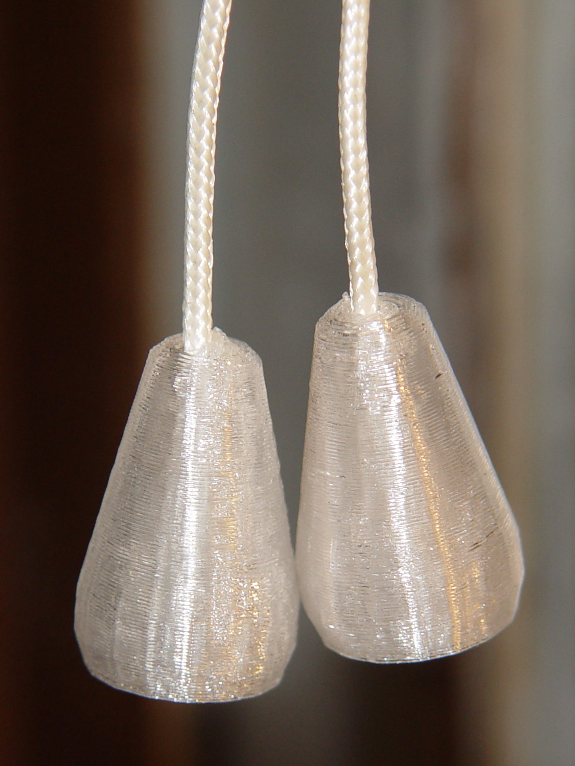
    After smashing one of the cord pulls between the sash and the frame:

    Miniblind cord caps - installed
    Miniblind cord caps – installed

    The glittery PETG looks surprisingly good in the sunlight that will eventually change it into dullness. The black flecks come from optical effects in the plastic, not the usual burned PETG snot.

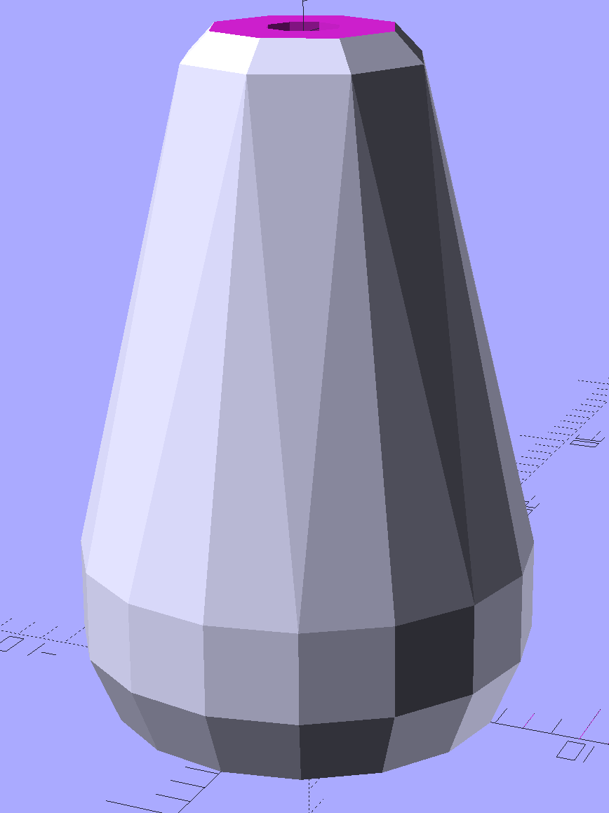
    The solid model is basically a hull around two “spheres”, truncated on top & bottom:

    Miniblind cord cap - solid model
    Miniblind cord cap – solid model

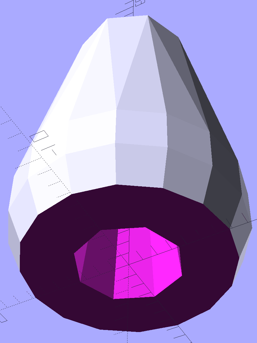
    The interior has a taper to accommodate the knot, but they’re chunky little gadgets:

    Miniblind cord cap - solid model - bottom
    Miniblind cord cap – solid model – bottom

    I thought the facets came out nicely, even if they’re mostly invisible in the picture.

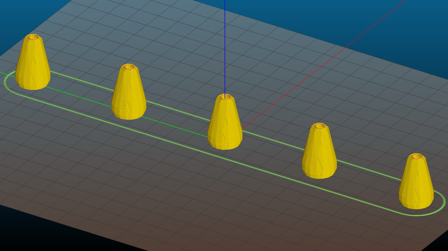
    Each pull should build separately to improve the surface finish, so I arranged five copies in sequence from front to back:

    Miniblind cord cap - 5 sequential - Slic3r preview
    Miniblind cord cap – 5 sequential – Slic3r preview

    If you’re using an M2, the fans hanging off the front of the filament drive housing might come a bit too close for comfort, so rotate ’em upward and out of the way.

    If you remove the interior features and flip ’em upside down, they’d work well in Spiral Vase mode. You’d have to manually drill the top hole, though, because a hole through the model produces two shells.

    The OpenSCAD source code as a GitHub Gist:

    // Cap for miniblind cord
    // Ed Nisley KE4ZNU – August 2016
    //- Extrusion parameters – must match reality!
    ThreadThick = 0.25;
    ThreadWidth = 0.40;
    Protrusion = 0.1;
    HoleWindage = 0.2;
    //——
    // Dimensions
    OD1 = 0;
    OD2 = 1;
    LENGTH = 2;
    Cap = [9.0,16.0,25.0];
    Cord = [2.5,7.0,Cap[LENGTH] – 5];
    NumSides = 8;
    //———————-
    //- Build it
    difference() {
    hull() { // overall shape
    translate([0,0,Cap[LENGTH] – Cap[OD1]/2])
    sphere(d=Cap[OD1],$fn=NumSides);
    translate([0,0,0.5*Cap[OD2]/2])
    sphere(d=Cap[OD2],$fn=2*NumSides); // round the bottom just a bit
    }
    translate([0,0,-Cap[LENGTH]/2]) // trim bottom
    cube([2*Cap[OD2],2*Cap[OD2],Cap[LENGTH]],center=true);
    translate([0,0,Cap[LENGTH] + 0.8*Cap[OD1]]) // trim top (arbitrarily)
    cube([2*Cap[OD1],2*Cap[OD1],2*Cap[OD1]],center=true);
    translate([0,0,-Protrusion])
    cylinder(d=Cord[OD1],h=(Cap[LENGTH] + 2*Protrusion),$fn=NumSides);
    translate([0,0,-Protrusion])
    cylinder(d1=Cord[OD2],d2=Cord[OD1],h=(Cord[LENGTH] + Protrusion),$fn=NumSides);
    }
  • Epson R380 Printer: Resetting the Waste Ink Counter Again

    The Epson R380 printer never gets turned off, so it rarely has a chance to complain. After a powerdown due to refreshing the UPS batteries, it lit up with the dreaded “Service required. Visit your friendly Epson repair center” message that indicates you should just throw the printer out, because replacing the internal ink absorber mats / draining the internal tank is, mmm, economically infeasible when you pay somebody else to do it.

    Having done this before, though, it’s almost easy…

    • Pop a PC with a Windows partition off the to-be-recycled stack
    • Boot System Rescue CD
    • Back up the partition to a junk hard drive, just for practice
    • Copy the subdirectory of sketchy utilities to the Windows drive
    • Boot Windows (with no network connection)
    • Run sketchy utility to reset the ink counter
    • Boot SRC, restore partition
    • Return hard drive & PC to their respective piles
    • Declare victory and move on

    This time, a sketchy utility that resembled the Official Epson Reset Program actually reset something and the printer started up normally. As before, however, the saved MBR didn’t match the on-disk MBR, suggesting that either I don’t understand how to save / restore the MBR or that something once again meddled with the MBR in between the backup and the restore.

    I’ve emptied the waste ink tank maybe three times since the last reset: plenty of ink down the drain. Fortunately, I loves me some good continuous-flow ink supply action…

    Sheesh & similar remarks.

  • Kenmore Progressive Vacuum Tool Adapters: First Failure

    I picked up a horsehair dust brush from eBay as a lightweight substitute for the Electrolux aluminum ball, discovered that an adapter I’d already made fit perfectly, did the happy dance, and printed one for the brush. That worked perfectly for half a year, whereupon:

    Dust Brush Adapter - broken parts
    Dust Brush Adapter – broken parts

    It broke about where I expected, along the layer lines at the cross section where the snout joins the fitting. You can see the three perimeter shells I hoped would strengthen the part:

    Dust Brush Adapter - layer separation
    Dust Brush Adapter – layer separation

    That has the usual 15% 3D Honeycomb infill, although there’s not a lot area for infill.

    There’s obviously a stress concentration there and making the wall somewhat thicker (to get more plastic-to-plastic area) might suffice. I’m not convinced the layer bonding would be good enough, even with more wall area, to resist the stress; that’s pretty much a textbook example of how & where 3D printed parts fail.

    That cross section should look like this:

    Dust Brush Adapter - Snout infill - Slic3r preview
    Dust Brush Adapter – Snout infill – Slic3r preview

    Anyhow, I buttered the snout’s broken end with JB Kwik epoxy, aligned the parts, and clamped them overnight:

    Dust Brush Adapter - clamping
    Dust Brush Adapter – clamping

    The source code now has a separate solid model for the dust brush featuring a slightly shorter snout; if when the epoxy fails, we’ll see how that changes the results. I could add ribs and suchlike along the outside, none of which seem worth the effort right now. Fairing the joint between those two straight sections would achieve the same end, with even more effort, because OpenSCAD.

    The OpenSCAD source code as a GitHub Gist:

    // Kenmore vacuum cleaner nozzle adapters
    // Ed Nisley KE4ZNU August 2016
    // Layout options
    Layout = "DustBrush"; // MaleFitting CoilWand FloorBrush CreviceTool ScrubbyTool LuxBrush DustBrush
    //- Extrusion parameters must match reality!
    // Print with +1 shells and 3 solid layers
    ThreadThick = 0.25;
    ThreadWidth = 0.40;
    HoleWindage = 0.2;
    function IntegerMultiple(Size,Unit) = Unit * ceil(Size / Unit);
    Protrusion = 0.1; // make holes end cleanly
    //———————-
    // Dimensions
    ID1 = 0; // for tapered tubes
    ID2 = 1;
    OD1 = 2;
    OD2 = 3;
    LENGTH = 4;
    OEMTube = [35.0,35.0,41.7,40.5,30.0]; // main fitting tube
    EndStop = [OEMTube[ID1],OEMTube[ID2],47.5,47.5,6.5]; // flange at end of main tube
    FittingOAL = OEMTube[LENGTH] + EndStop[LENGTH];
    $fn = 12*4;
    //———————-
    // Useful routines
    module PolyCyl(Dia,Height,ForceSides=0) { // based on nophead's polyholes
    Sides = (ForceSides != 0) ? ForceSides : (ceil(Dia) + 2);
    FixDia = Dia / cos(180/Sides);
    cylinder(r=(FixDia + HoleWindage)/2,h=Height,$fn=Sides);
    }
    //——————-
    // Male fitting on end of Kenmore tools
    // This slides into the end of the handle or wand and latches firmly in place
    module MaleFitting() {
    Latch = [40,11.5,5.0]; // rectangle latch opening
    EntryAngle = 45; // latch entry ramp
    EntrySides = 16;
    EntryHeight = 15.0; // lower edge on *inside* of fitting
    KeyRadius = 1.0;
    translate([0,0,6.5])
    difference() {
    union() {
    cylinder(d1=OEMTube[OD1],d2=OEMTube[OD2],h=OEMTube[LENGTH]); // main tube
    hull() // insertion guide
    for (i=[-(6.0/2 – KeyRadius),(6.0/2 – KeyRadius)],
    j=[-(28.0/2 – KeyRadius),(28.0/2 – KeyRadius)],
    k=[-(26.0/2 – KeyRadius),(26.0/2 – KeyRadius)])
    translate([(i – (OEMTube[ID1]/2 + OEMTube[OD1]/2)/2 + 6.0/2),j,(k + 26.0/2 – 1.0)])
    sphere(r=KeyRadius,$fn=8);
    translate([0,0,-EndStop[LENGTH]]) // wand tube butts against this
    cylinder(d=EndStop[OD1],h=EndStop[LENGTH] + Protrusion);
    }
    translate([0,0,-OEMTube[LENGTH]]) // main bore
    cylinder(d=OEMTube[ID1],h=2*OEMTube[LENGTH] + 2*Protrusion);
    translate([0,-11.5/2,23.0 – 5.0]) // latch opening
    cube(Latch);
    translate([OEMTube[ID1]/2 + EntryHeight/tan(90-EntryAngle),0,0]) // latch ramp
    translate([(Latch[1]/cos(180/EntrySides))*cos(EntryAngle)/2,0,(Latch[1]/cos(180/EntrySides))*sin(EntryAngle)/2])
    rotate([0,-EntryAngle,0])
    intersection() {
    rotate(180/EntrySides)
    PolyCyl(Latch[1],Latch[0],EntrySides);
    translate([-(2*Latch[0])/2,0,-Protrusion])
    cube(2*Latch[0],center=true);
    }
    }
    }
    //——————-
    // Refrigerator evaporator coil wand
    module CoilWand() {
    union() {
    translate([0,0,50.0])
    rotate([180,0,0])
    difference() {
    cylinder(d1=EndStop[OD1],d2=42.0,h=50.0);
    translate([0,0,-Protrusion])
    cylinder(d1=35.0,d2=35.8,h=100);
    }
    translate([0,0,50.0 – Protrusion])
    MaleFitting();
    }
    }
    //——————-
    // Samsung floor brush
    module FloorBrush() {
    union() {
    translate([0,0,60.0])
    rotate([180,0,0])
    difference() {
    union() {
    cylinder(d1=EndStop[OD1],d2=32.4,h=10.0);
    translate([0,0,10.0 – Protrusion])
    cylinder(d1=32.4,d2=30.7,h=50.0 + Protrusion);
    }
    translate([0,0,-Protrusion])
    cylinder(d1=28.0,d2=24.0,h=100);
    }
    translate([0,0,60.0 – Protrusion])
    MaleFitting();
    }
    }
    //——————-
    // Crevice tool
    module CreviceTool() {
    union() {
    translate([0,0,60.0])
    rotate([180,0,0])
    difference() {
    union() {
    cylinder(d1=EndStop[OD1],d2=32.0,h=10.0);
    translate([0,0,10.0 – Protrusion])
    cylinder(d1=32.0,d2=30.4,h=50.0 + Protrusion);
    }
    translate([0,0,-Protrusion])
    cylinder(d1=28.0,d2=24.0,h=100);
    }
    translate([0,0,60.0 – Protrusion])
    MaleFitting();
    }
    }
    //——————-
    // Mystery brush
    module ScrubbyTool() {
    union() {
    translate([0,0,60.0])
    rotate([180,0,0])
    difference() {
    union() {
    cylinder(d1=EndStop[OD1],d2=31.8,h=10.0);
    translate([0,0,10.0 – Protrusion])
    cylinder(d1=31.8,d2=31.0,h=50.0 + Protrusion);
    }
    translate([0,0,-Protrusion])
    cylinder(d1=26.0,d2=24.0,h=100);
    }
    translate([0,0,60.0 – Protrusion])
    MaleFitting();
    }
    }
    //——————-
    // eBay horsehair dusting brush
    module DustBrush() {
    union() {
    translate([0,0,40.0])
    rotate([180,0,0])
    difference() {
    union() {
    cylinder(d1=EndStop[OD1],d2=31.8,h=10.0);
    translate([0,0,10.0 – Protrusion])
    cylinder(d1=31.6,d2=31.8,h=30.0 + Protrusion);
    }
    translate([0,0,-Protrusion])
    cylinder(d1=26.0,d2=24.0,h=100);
    }
    translate([0,0,40.0 – Protrusion])
    MaleFitting();
    }
    }
    //——————-
    // Electrolux brush ball
    module LuxBrush() {
    union() {
    translate([0,0,30.0])
    rotate([180,0,0])
    difference() {
    union() {
    cylinder(d1=EndStop[OD1],d2=30.8,h=10.0);
    translate([0,0,10.0 – Protrusion])
    cylinder(d1=30.8,d2=30.0,h=20.0 + Protrusion);
    }
    translate([0,0,-Protrusion])
    cylinder(d1=25.0,d2=23.0,h=30 + 2*Protrusion);
    }
    translate([0,0,30.0 – Protrusion])
    MaleFitting();
    }
    }
    //———————-
    // Build it!
    if (Layout == "MaleFitting")
    MaleFitting();
    if (Layout == "CoilWand")
    CoilWand();
    if (Layout == "FloorBrush")
    FloorBrush();
    if (Layout == "CreviceTool")
    CreviceTool();
    if (Layout == "DustBrush")
    DustBrush();
    if (Layout == "ScrubbyTool")
    ScrubbyTool();
    if (Layout == "LuxBrush")
    LuxBrush();


  • Michelin Protek Max Tubes

    Within the space of four days, we had three rear-tire flats:

    • A tire liner wear-through, after which I didn’t replace the liner
    • Four miles later, a blowout through a tread gash previously covered by the tire liner
    • A puncture flat directly through the tread

    Basically, erosion from the (last remaining, I think) liner in the rear tire of Mary’s bike caused the first flat; I patched the tube and didn’t notice the gash. After the blowout, I patched the tube again, booted the gash (with a snippet from a roll of PET bottle plastic I carry around for exactly that purpose), stuck an ordinary patch atop the boot to cover its edges, and the whole mess has held air just fine for the last week. I’m reluctant to mess with success.

    Not having a tire liner caused the third flat, this time on my bike. The wound looked like a nail or glass shard punched directly through the Kevlar armor behind the tread. Fortunately, it happened (or, more exactly, I realized I had a flat) half a mile from home, so I fired a CO2 cartridge into the tube and pedaled like crazy, which got me halfway to the goal and I rolled the rest of the way on a dead-flat tire.

    Ya can’t win.

    So I picked up a pair of Michelin Protek Max tubes, the weirdest things I’ve ever stuffed into a bike tire:

    Michelin Protek Max Tube - carton
    Michelin Protek Max Tube – carton

    The bumps along the tread surface are much larger and uglier than shown in that picture:

    Michelin Protek Max tube
    Michelin Protek Max tube

    The rubber forming the protrusions has the same thickness as the rest of the tube, so you’re looking at soft, flexible shapes, rather than thick bumps.

    The “liquid” inside must be a thin film over the inner surface. I’ve never been a big fan of tire sealants, mostly because they’re reputed to ooze to the bottom of the tire into off-balance puddles.

    For future reference, the Official Quasi-Instruction Manual / Blurb (clicky for more dots):

    Michelin Protek Max Tube - instructions
    Michelin Protek Max Tube – instructions

    We’ll see how well these work…

  • BOB Yak Fender Fracture: Fixed

    We agreed that repairing the failed flag ferrule made the trailer much quieter, but it still seemed far more rattly than we remembered. It just had to be the fender, somehow, and eventually this appeared:

    BOB Yak Fender Mount - fractures
    BOB Yak Fender Mount – fractures

    The obviously missing piece of the fender fell out in my hand; the similar chunk just beyond the wire arch fell out after I took the pictures. Yes, the wire has indented the fender.

    The arch supports the aluminum fender, with a pair of (flat) steel plates clamping the wire to the fender:

    BOB Yak Fender Mount - screw plates and pads
    BOB Yak Fender Mount – screw plates and pads

    The cardboard scraps show I fixed a rattle in the distant past.

    Being aluminum, the fender can’t have a replacement piece brazed in place and, given the compound curves, I wasn’t up for the requisite fancy sheet metal work.

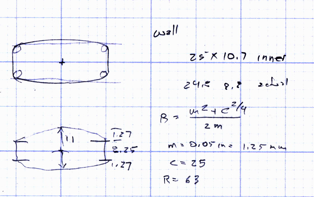
    Instead, a bit of math produces a pair of shapes:

    BOB Yak Fender Mount - solid model
    BOB Yak Fender Mount – solid model

    In this case, we know the curve radii, so the chord equation gives the depth of the curve across the (known) width & length of the plates; the maximum of those values sets the additional thickness required for the plates. The curves turn out to be rather steep, given the usual layer thickness and plate sizes, which gives them a weird angular look that absolutely doesn’t matter when pressed firmly against the fender:

    BOB Yak Fender Mount - Slic3r preview
    BOB Yak Fender Mount – Slic3r preview

    The computations required to fit Hilbert Curve surface infill into those small exposed areas took basically forever; given that nobody will ever see them, I used the traditional linear infill pattern. A 15% 3D Honeycomb interior infill turned them into rigid parts.

    The notch in the outer plate (top left, seen notch-side-down) accommodates the support wire:

    BOB Yak Fender Mount - outer
    BOB Yak Fender Mount – outer

    The upper surface would look better with chamfered edges, but that’s in the nature of fine tuning. That part must print with its top surface downward: an unsupported (shallow) chamfer would produce horrible surface finish and life is too short for fussing with support. Given the surrounding rust & dings, worrying about aesthetics seems bootless.

    The original screws weren’t quite long enough to reach through the plastic plates, so I dipped into my shiny-new assortment of stainless steel socket head cap screws. Although the (uncut) M5x16 screws seem to protrude dangerously far from the inner plate, there’s another inch of air between those screws and the tire tread:

    BOB Yak Fender Mount - inner
    BOB Yak Fender Mount – inner

    Given the increase in bearing area, that part of the fender shouldn’t fracture for another decade or two.

    I loves me my M2 3D printer …

    The OpenSCAD source code as a GitHub Gist:

    // BOB Yak Fender Mounting Bracket
    // Ed Nisley – KE4ZNU – July 2016
    Layout = "Build"; // Build Fender Rod BlockInner BlockOuter
    //- Extrusion parameters must match reality!
    // Print with 1 shell and 3 solid layers
    ThreadThick = 0.25;
    ThreadWidth = 0.40;
    HoleWindage = 0.3;
    Protrusion = 0.1; // make holes end cleanly
    inch = 25.4;
    //———————-
    // Dimensions
    IR = 0; // radii seem easier to measure here
    OR = 1;
    LENGTH = 2;
    Fender = [25,220,1]; // minor major thickness
    FenderSides = 128;
    FenderRod = [5.0/2,(Fender[IR] + 10),5.0/2]; // support rod dia/2, arch radius, rod dia/2 again
    ChordMajor = Fender[OR] – sqrt(pow(Fender[OR],2) – pow(40,2)/4);
    ChordMinor = Fender[IR] – sqrt(pow(Fender[IR],2) – pow(25,2)/4);
    ChordFit = max(ChordMajor,ChordMinor);
    echo("Chords: ",ChordMajor,ChordMinor,ChordFit);
    BlockInnerOA = [40,25,1 + ChordFit];
    BlockOuterOA = [35,25,2 + ChordFit];
    echo(str("Inner Block: ",BlockInnerOA));
    echo(str("Outer Block: ",BlockOuterOA));
    ScrewOD = 5.0;
    ScrewOC = 20.0;
    NumSides = 6*4;
    //———————-
    // Useful routines
    module PolyCyl(Dia,Height,ForceSides=0) { // based on nophead's polyholes
    Sides = (ForceSides != 0) ? ForceSides : (ceil(Dia) + 2);
    FixDia = Dia / cos(180/Sides);
    cylinder(r=(FixDia + HoleWindage)/2,
    h=Height,
    $fn=Sides);
    }
    module FenderShape() {
    rotate([90,0*180/FenderSides,0])
    rotate_extrude(angle=180,$fn=FenderSides)
    translate([(Fender[OR] – Fender[IR]),0])
    circle(r=Fender[IR],$fn=2*NumSides);
    }
    module RodShape() {
    rotate([90,0*180/FenderSides,0])
    rotate_extrude(angle=180,convexity=2,$fn=FenderSides)
    translate([(FenderRod[OR] – FenderRod[IR]),0])
    circle(r=FenderRod[IR],$fn=NumSides);
    }
    module BlockInner() {
    intersection() {
    difference() {
    linear_extrude(height=BlockInnerOA[LENGTH],convexity=3)
    hull() {
    for (i=[-1,1])
    translate([i*(BlockInnerOA[0]/2 – BlockInnerOA[1]/2),0,0])
    circle(d=BlockInnerOA[1]);
    }
    for (i=[-1,1])
    translate([i*(ScrewOC/2),0,-Protrusion])
    PolyCyl(ScrewOD,2*BlockInnerOA[2],6);
    }
    translate([0,0,(BlockInnerOA[2] – Fender[OR])])
    FenderShape();
    }
    }
    module BlockOuter() {
    difference() {
    linear_extrude(height=BlockOuterOA[LENGTH],convexity=4)
    hull() {
    for (i=[-1,1])
    translate([i*(BlockOuterOA[0]/2 – BlockOuterOA[1]/2),0,0])
    circle(d=BlockOuterOA[1]);
    }
    for (i=[-1,1])
    translate([i*(ScrewOC/2),0,-Protrusion])
    PolyCyl(ScrewOD,2*BlockOuterOA[2],6);
    translate([0,0,(BlockOuterOA[2] – ChordFit + Fender[OR])])
    rotate([180,0,0])
    FenderShape();
    translate([0,0,(FenderRod[OR] – 2*FenderRod[IR])])
    rotate([180,0,90])
    RodShape();
    }
    }
    //- Build things
    if (Layout == "Fender")
    FenderShape();
    if (Layout == "Rod")
    RodShape();
    if (Layout == "BlockInner")
    BlockInner();
    if (Layout == "BlockOuter")
    BlockOuter();
    if (Layout == "Build") {
    translate([0,-BlockInnerOA[0]/2,0])
    BlockInner();
    translate([0,BlockOuterOA[0]/2,0])
    BlockOuter();
    }

    The original dimension measurement and design doodle:

    BOB Yak Fender Mount - doodles
    BOB Yak Fender Mount – doodles
  • BOB Yak Flag Ferrule Failure

    At some point along a recent grocery ride, the top half of the flag mast on the BOB Yak trailer went missing.

    We had a general idea of where it happened, but, fortunately, I Have The Technology:

    This slideshow requires JavaScript.

    The flag and pole ended up just off the road, only slightly the worse for wear. I hadn’t planned on riding two dozen miles on a rather hot and humid summer day, but so it goes.

    The lower ferrule chafed away enough of the fiberglass pole that it could slip downward, eventually releasing the upper ferrule:

    BOB Yak Flag - ferrule chafing
    BOB Yak Flag – ferrule chafing

    That split near the end enlarged the pole enough that the ferrule couldn’t slide off, so I contented myself with cross-drilling the whole affair for a 1-72 screw, packing epoxy into the hole, tucking more epoxy up inside the bottom end of the ferrule, then burying the screw and nut:

    BOB Yak Flag - reassembled ferrule
    BOB Yak Flag – reassembled ferrule

    While I had it on the bench, I replaced the somewhat shredded fluorescent orange tape just under the flag and added a strip of diagonally striped red-and-white retroreflective tape for an attractive barber-pole appearance.

    That should last for a little while longer…


  • Mini-Lathe: Electronics Box Screw Insert

    Two bags of knurled brass M4 inserts arrived from halfway around the planet, so I could fix the offending hole behind the LMS mini-lathe’s electronics box:

    LMS Mini-lathe - mistapped cover hole
    LMS Mini-lathe – mistapped cover hole

    Although you should remove the lathe from the chip pan and do it right, I gimmicked up a reducer for the long drill extension that, IIRC, came with the house:

    LMS mini-lathe - drill bit extension
    LMS mini-lathe – drill bit extension

    I figured that would be close enough, given the starting situation. The cast iron frame is perhaps half an inch thick at that point, with steel brackets bolted to the far side, so use the hole as a guide and don’t drill with wild abandon.

    A long M4 screw serves to align the insert eyeballometrically perpendicular to the surface while the JB Kwik epoxy cured:

    LMS mini-lathe - insert alignment
    LMS mini-lathe – insert alignment

    It definitely doesn’t look like it grew there and, indeed, looks like the obvious repair job it is:

    LMS mini-lathe - insert epoxied
    LMS mini-lathe – insert epoxied

    I thought about replacing all the screws, but decided it was so well hidden that, if I didn’t tell anybody, they’d never know:

    LMS mini-lathe - cover screw installed
    LMS mini-lathe – cover screw installed

    Done!