The Smell of Molten Projects in the Morning

Ed Nisley's Blog: Shop notes, electronics, firmware, machinery, 3D printing, laser cuttery, and curiosities. Contents: 100% human thinking, 0% AI slop.

Tag: Mini-lathe

Tweaking an LMS 5200 Mini-Lathe

  • Ball Drilling Misadventure

    Ball Drilling Misadventure

    My new bike helmet mirror mounts required poking a 3.6 mm hole through a 10 mm polypropylene ball:

    Helmet Mirror Ball Mount - drilled ball test
    Helmet Mirror Ball Mount – drilled ball test

    Although how I did it worked, it wasn’t pretty.

    I had a Micromark Spherical Object Drilling and Finishing Vise which was obviously intended for smaller holes in less challenging objects:

    Micromark Ball Vise - overview
    Micromark Ball Vise – overview

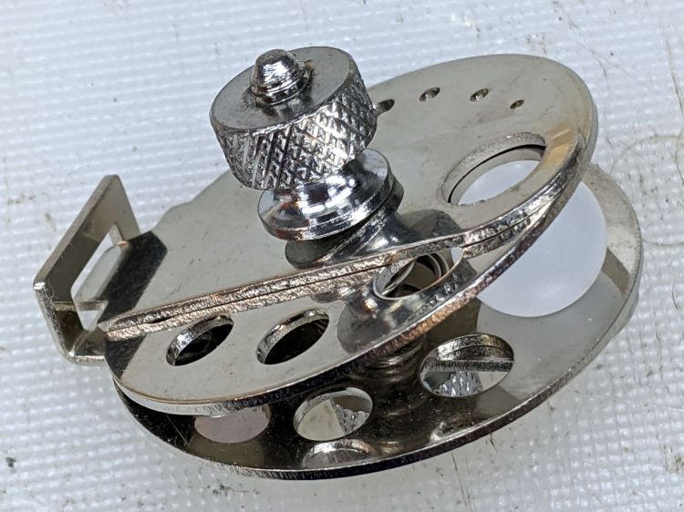
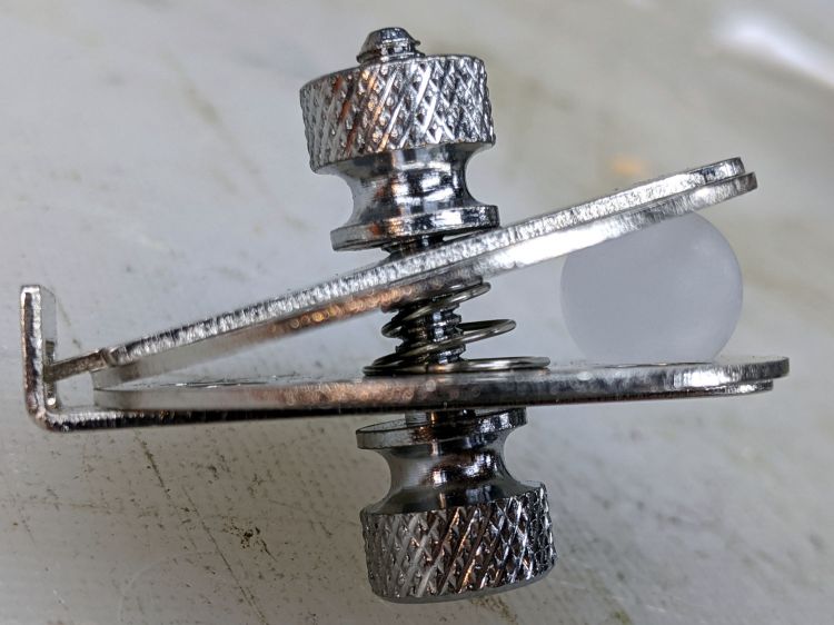
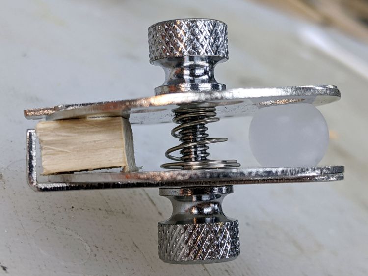
    Given the angle between the two plates, I didn’t see any way to put a large hole though the center of the ball:

    Micromark Ball Vise - 10 mm ball
    Micromark Ball Vise – 10 mm ball

    A scrap of wood aligned the two plates somewhat better:

    Micromark Ball Vise - wood block
    Micromark Ball Vise – wood block

    With that as a hint, the Box o’ Brass Cutoffs disgorged a better spacer, although the original screw was just an itsy too short:

    Micromark Ball Vise - brass tube
    Micromark Ball Vise – brass tube

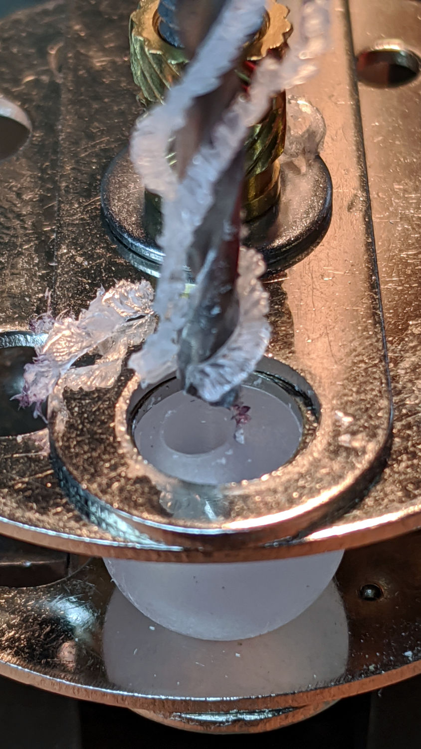
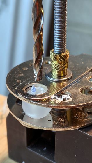
    Grabbing the modified vise in a machinist’s vise got me most of the way toward the goal:

    Micromark Ball Vise - drill press
    Micromark Ball Vise – drill press

    Polypropylene is grabby, so the drill stuck / rotated the ball inside the vise / made a mess:

    Micromark Ball Vise - offset hole
    Micromark Ball Vise – offset hole

    A close look at the top picture shows the nasty ring around the hole (on the right side). The vise grips the ball between two holes punched in the metal plates, contacting it only at the right-angle (-ish) edges forming two rings, so there’s really not enough friction against the plastic to hold the ball in position and any slippage results in a gouge. Perhaps pearls / beads / jewelry behave differently?

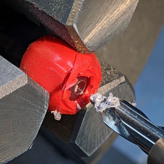
    Fortunately, I had a bag of 100 balls, so a few failures gave me enough of a clue to do what I should have done from the beginning:

    Micromark Ball Vise - lathe ball hack
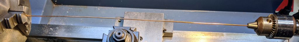
    Micromark Ball Vise – lathe ball hack

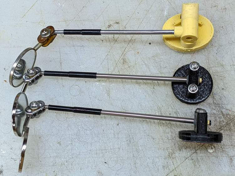
    That’s silicone tape wrapped around a ball grabbed in the lathe chuck, with a center drill in the tailstock. There’s barely enough traction between the ball and the chuck to get the job done, but it worked out well enough to build a few new mirrors:

    Helmet Mirror Ball Mount - new vs old
    Helmet Mirror Ball Mount – new vs old

    There’s obviously a better way, although it took a few weeks to shake out the solid model …

  • Simple Small File Handles

    Simple Small File Handles

    I finally got around to making handles for some small files:

    Simple file handles - installed
    Simple file handles – installed

    You’re allowed to drill wood on a metal lathe, although running a vacuum cleaner to collect the fine dust is a Good Idea:

    Simple file handles - hole drilling
    Simple file handles – hole drilling

    Yes, I could 3D print nice knurled handles, but these are something of an homage to my father’s small files with similar wood handles.

    I’ve been meaning to do this for … decades …

  • Kenmore Progressive Vacuum Cleaner vs. Dust Brush Adapters

    Kenmore Progressive Vacuum Cleaner vs. Dust Brush Adapters

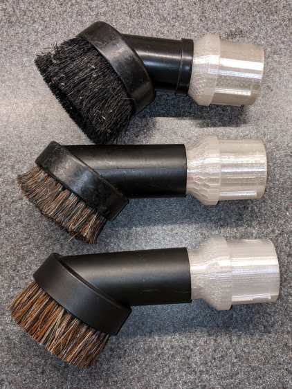
    Contemporary vacuum cleaner dust brush heads have bristles in some combination of [long | short] with [flexy | stiff]. The long + flexy combination results in the bristles jamming the inlet and the short + stiff combo seems unsuited for complex surfaces. Shaking the Amazonian dice brought a different combination:

    Vacuum cleaner dust brush assortment - with adapters
    Vacuum cleaner dust brush assortment – with adapters

    That’s the new one on the bottom and, contrary to what you might think from the picture, it is not identical to the one just above it.

    In particular, the black plastic housing came from a different mold (the seam lines are now top-and-bottom) and required a new adapter for the Kenmore Progressive vacuum cleaner’s complicated wand / hose inlet, with a 3/4 inch PVC pipe reinforcement inside.

    Early reports indicate it works fine, so I’ll declare a temporary victory in the war on entropy.

    I’m still using the same OpenSCAD source code with minute tweaks to suit the as-measured tapers.

  • Bike Helmet Mirror: Brasswork Clamp

    Bike Helmet Mirror: Brasswork Clamp

    A bit of Quality Shop Time produced a slight improvement to the clamp holding the mirror to the stalk:

    Helmet Mirror Ball Mount - mirror joint brasswork
    Helmet Mirror Ball Mount – mirror joint brasswork

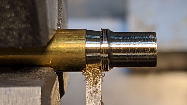
    The general idea is to hold the wave washer (it’s mashed under the flat washer, honest) above those bumps on the plate holding the mirror and stalk balls. It’s a few millimeters from the end of a ¼ inch brass rod, drilled for the M3 screw, and reduced to 4.5 mm with a parting tool to clear the bumps.

    While I was at it, I made two spare mirrors, just to have ’em around:

    Helmet Mirror Ball Mount - new vs old
    Helmet Mirror Ball Mount – new vs old

    The new ball mount looks downright svelte compared to the old Az-El mount, doesn’t it?

    I should replace the steel clamp plates with a stainless-steel doodad of some sort to eliminate the unsightly rust, but that’s definitely in the nature of fine tuning.

  • More AAA-to-AA Alkaline Adapters

    More AAA-to-AA Alkaline Adapters

    Having a handful of not-dead-yet AAA alkalines and a bunch of LED blinkies built for AA alkalines, a pair of adapters seemed in order:

    AAA-to-AA Alkaline Adapters - installed
    AAA-to-AA Alkaline Adapters – installed

    The blinkies need a somewhat wider base than they’d get from a pair of AAA alkalines, so it’s not quite as dumb as it may seem.

    In any event, the positive terminal comes from a brass rod:

    AAA-to-AA Alkaline Adapters - brass terminal
    AAA-to-AA Alkaline Adapters – brass terminal

    Nobody will ever see the fancy Hilbert Curve infill around the brass:

    AAA-to-AA Alkaline Adapters - end view
    AAA-to-AA Alkaline Adapters – end view

    In this application, they’ll go from not-dead-yet to oh-it’s-dead faster than AA cells, so I can watch how the blinkies work with lower voltages.

  • Bike Helmet Mirror: Ball Mount

    Bike Helmet Mirror: Ball Mount

    Nine years ago, I didn’t know how enough to design a bike helmet mirror with a ball mount, but even an old dog can learn a new trick:

    Helmet Mirror Ball Mount - on helmet
    Helmet Mirror Ball Mount – on helmet

    However, it’s worth noting my original, butt-ugly Az-El mounts lasted for all of those nine years, admittedly with adjustments along the way, which is far more than the commercial mounts making me unhappy enough to scratch my itch.

    The mount adapts the split spherical clamp from the daytime running light:

    Helmet Mirror Mount - Ball
    Helmet Mirror Mount – Ball

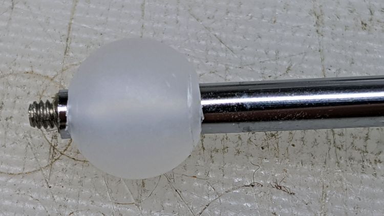
    Scaling it down for a 10 mm polypropylene ball around the base of the 30 mm inspection mirror’s shaft simplified everything:

    Helmet Mirror Ball Mount - drilled ball test
    Helmet Mirror Ball Mount – drilled ball test

    I’m reasonably sure I couldn’t have bought 100 polypro balls for eight bucks a decade ago, but we’ll never know. Drilling the hole was a complete botch job, about which more later. The shaft came from a spare mirror mount I made up a while ago; a new shaft appears below.

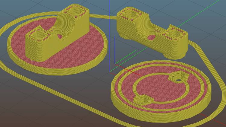
    The solid model, like Gaul, is in three parts divided:

    Helmet Mirror Ball Mount - Slic3r
    Helmet Mirror Ball Mount – Slic3r

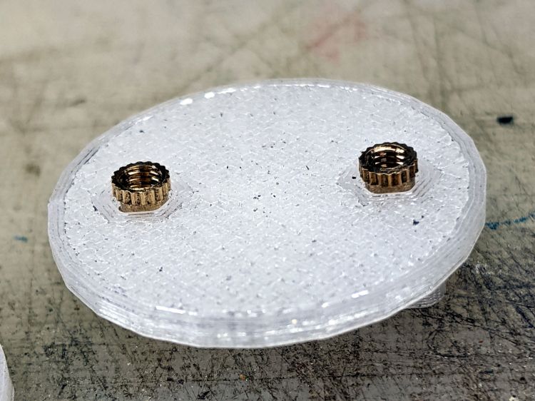
    The helmet plate (on the right) has a slight indent more-or-less matching the helmet curvature and gets a layer of good double-stick foam tape. The clamp base (on the left) has a pair of brass inserts epoxied into matching recesses below the M3 clearance holes:

    Helmet Mirror Ball Mount - inserts
    Helmet Mirror Ball Mount – inserts

    A layer of epoxy then sticks the helmet plate in place, with the inserts providing positive alignment:

    Helmet Mirror Ball Mount - plates
    Helmet Mirror Ball Mount – plates

    The clamp screws pull the inserts against the plastic in the clamp base, so they can’t pull out or through, and the plates give the epoxy enough bonding surface that (I’m pretty sure) they won’t ever come apart.

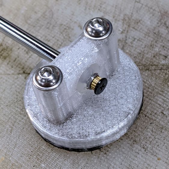
    I turned down a 2 mm brass insert to fit inside the butt end of the mirror shaft and topped it off with a random screw harvested from a dead hard drive:

    Helmet Mirror Ball Mount - assembled - rear view
    Helmet Mirror Ball Mount – assembled – rear view

    At the start, it wasn’t obvious the shaft would stay stuck in the ball, so I figured making it impossible to pull out would eliminate the need to find it by the side of the road. As things turned out, the clamp exerts enough force to ensure the shaft ain’t goin’ nowhere, so I’ll plug future shafts with epoxy.

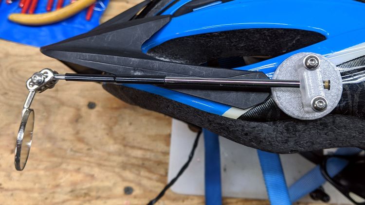
    The front side of the clamp looks downright sleek:

    Helmet Mirror Ball Mount - assembled - front view
    Helmet Mirror Ball Mount – assembled – front view

    Well, how about “chunky”?

    The weird gray-black highlights are optical effects from clear / natural PETG, rather than embedded grunge; it looks better in person. I should have used retina-burn orange or stylin’ black.

    This mount is much smaller than the old one and should, in the event of a crash, not cause much injury. Based on how the running light clamp fractures, I expect the clamp will simply tear out of the base on impact. In the last decade, neither of us has crashed, so I don’t know what the old mount would do.

    The clamp is 7 mm thick (front-to-back), set by the M3 washer diameter, with 1.5 mm of ball sticking out on each side. The model has a kerf one thread high (0.25 mm) between the pieces to add clamping force and, with the screws tightened down, moving the ball requires a disturbingly large effort. I added a touch of rosin and that ball straight-up won’t move, which probably means the shaft will bend upon droppage; I have several spare mirrors in stock.

    On the other paw, the ball turns smoothly in the clamp and it’s easy to position the shaft as needed: much better than the old Az-El mount!

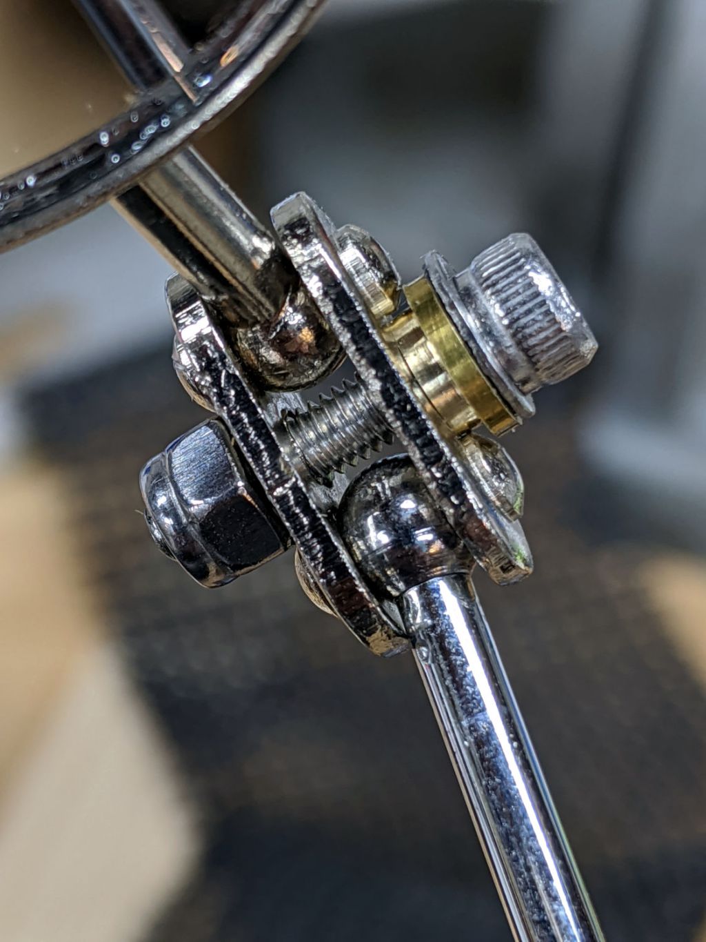
    The inspection mirror hangs from a double ball joint which arrives with a crappy screw + nut. I epoxied the old mirror mount nut in place, but this time around I drilled the plates for a 3 mm stainless SHCS, used a wave washer for a bit of flexible force, and topped it off with a nyloc nut:

    Helmet Mirror Ball Mount - mirror joint
    Helmet Mirror Ball Mount – mirror joint

    I’m unhappy with how it looks and don’t like how the washer hangs in free space between those bumps, so I may eventually turn little brass fittings to even things out. It’s either that or more epoxy.

    So far, though, it’s working pretty well and both units meet customer requirements.

    The OpenSCAD source code as a GitHub Gist:

    // Bike helmet mirror mount – ball joint
    // Ed Nisley KE4ZNU 2020-09
    /* [Layout options] */
    Layout = "Build"; // [Build, Show, Plate, Base, Clamp]
    //– Extrusion parameters
    // Extrusion parameters
    /* [Hidden] */
    ThreadThick = 0.25;
    ThreadWidth = 0.40;
    HoleWindage = 0.2;
    function IntegerMultiple(Size,Unit) = Unit * ceil(Size / Unit);
    function IntegerLessMultiple(Size,Unit) = Unit * floor(Size / Unit);
    Protrusion = 0.1; // make holes end cleanly
    inch = 25.4;
    ID = 0;
    OD = 1;
    LENGTH = 2;
    //- Basic dimensions
    MountDia = 30.0; // footprint on helmet
    BallDia = 10.0;
    BallRad = BallDia / 2;
    WallThick = IntegerMultiple(2.0,ThreadWidth);
    FloorThick = IntegerMultiple(2.0,ThreadThick);
    CornerRound = 2.0;
    Insert = [3.0,4.0,4.0]; // threaded brass insert
    Screw = [3.0,5.5,25.0]; // clamp screw
    Washer = [3.7,7.0,0.7]; // washer
    ShowGap = 2.0;
    BuildGap = 5.0;
    //– Helmet Interface Plate
    ScrewOC = BallDia + 2*WallThick + Screw[ID];
    echo(str("Screw OC: ",ScrewOC));
    Clamp = [ceil(Washer[OD]), // barely holds washer under screw
    ScrewOC + Washer[OD], // minimal clearance for washer
    BallDia +2*FloorThick // screw fits through insert
    ];
    Kerf = ThreadThick;
    echo(str("Clamp: ",Clamp));
    HelmetCX = 60.0; // empirical helmet side curve
    HelmetMX = 3.0;
    HelmetRX = (pow(HelmetMX,2) + pow(HelmetCX,2)/4)/(2*HelmetMX);
    HelmetPlateC = MountDia;
    HelmetPlateTheta = atan(HelmetPlateC/HelmetRX);
    HelmetPlateM = 2*HelmetRX*pow(sin(HelmetPlateTheta/4),2);
    echo(str("Plate indent: ",HelmetPlateM));
    HelmetPlateThick = max(FloorThick,0.6*Insert[LENGTH]) + HelmetPlateM;
    echo(str("Screw length: ",Clamp.z + Insert[LENGTH]));
    MountSides = 2*3*4;
    //———————-
    // Useful routines
    module PolyCyl(Dia,Height,ForceSides=0) { // based on nophead's polyholes
    Sides = (ForceSides != 0) ? ForceSides : (ceil(Dia) + 2);
    FixDia = Dia / cos(180/Sides);
    cylinder(r=(FixDia + HoleWindage)/2,h=Height,$fn=Sides);
    }
    //———————-
    // Clamp frame around ball
    module ClampFrame() {
    difference() {
    union() {
    hull()
    for (i=[-1,1], j=[-1,1]) {
    translate([i*(Clamp.x/2 – CornerRound),j*(Clamp.y/2 – CornerRound),Clamp.z/2 – CornerRound])
    sphere(r=CornerRound,$fn=24);
    translate([i*(Clamp.x/2 – CornerRound),j*(Clamp.y/2 – CornerRound),-Clamp.z/2])
    cylinder(r=CornerRound,$fn=24);
    }
    for (j=[-1,1])
    translate([0,j*ScrewOC/2,0])
    rotate(180/12)
    cylinder(d=Washer[OD],h=Clamp.z/2,$fn=12);
    }
    sphere(d=BallDia + HoleWindage,$fn=48);
    cube([2*MountDia,2*MountDia,Kerf],center=true);
    for (j=[-1,1])
    translate([0,j*ScrewOC/2,-Screw[LENGTH]])
    rotate(180/6)
    PolyCyl(Screw[ID],2*Screw[LENGTH],6);
    }
    }
    module ClampSelect(Section) {
    XlateZ = (Section == "Top") ? Clamp.z/2 :
    (Section == "Bottom") ? -Clamp.z/2 :
    0;
    intersection(convexity=5) {
    ClampFrame();
    translate([0,0,XlateZ])
    cube([2*Clamp.x,2*Clamp.y,Clamp.z + 2*Protrusion],center=true);
    }
    }
    //———————-
    // Concave plate fitting helmet shell
    module HelmetPlate() {
    render()
    difference() {
    cylinder(d=MountDia,h=HelmetPlateThick,$fn=MountSides);
    translate([0,0,HelmetPlateThick – HelmetPlateM + HelmetRX])
    sphere(r=HelmetRX,$fn=128);
    for (j=[-1,1])
    translate([0,j*ScrewOC/2,-Protrusion]) {
    PolyCyl(Insert[OD],0.6*Insert[LENGTH] + Protrusion,6);
    PolyCyl(Screw[ID],2*HelmetPlateThick,6);
    }
    }
    }
    //———————-
    // Base of clamp ring
    module MountBase() {
    difference() {
    union() {
    cylinder(d=MountDia,h=FloorThick,$fn=MountSides);
    translate([0,0,FloorThick + Clamp.z/2])
    ClampSelect("Bottom");
    }
    for (j=[-1,1])
    translate([0,j*ScrewOC/2,-Protrusion])
    rotate(180/6)
    PolyCyl(Insert[OD],0.6*Insert[LENGTH] + Protrusion,6);
    }
    }
    //———————-
    // Lash it together
    if (Layout == "Plate") {
    HelmetPlate();
    }
    if (Layout == "Base") {
    MountBase();
    }
    if (Layout == "Clamp") {
    ClampFrame();
    }
    if (Layout == "Show") {
    rotate([180,0,0])
    HelmetPlate();
    translate([0,0,ShowGap]) {
    MountBase();
    color("Ivory",0.3)
    translate([0,0,Clamp.z/2 + FloorThick + ShowGap/2])
    sphere(d=BallDia);
    translate([0,0,Clamp.z/2 + FloorThick + ShowGap])
    ClampSelect("Top");
    }
    }
    if (Layout == "Build") {
    translate([MountDia/2 + BuildGap,0,0])
    HelmetPlate();
    translate([-(MountDia/2 + BuildGap),0,0])
    MountBase();
    translate([0,MountDia/2 + BuildGap,Clamp.z/2])
    rotate([0,180,0])
    rotate(90)
    ClampSelect("Top");
    }

    The original doodles include a bit of dress-up fairing that didn’t make the cut:

    Helmet Mirror Ball Mount - doodles
    Helmet Mirror Ball Mount – doodles
  • Lathe-straightened Copper Wire

    Lathe-straightened Copper Wire

    I formerly straightened the copper wire into “bus bars” for the astable multivibrators by whacking it with a slide hammer, but someone whose name is lost in the mists of time told me the right way to do it:

    Lathe-straightening Wire - setup
    Lathe-straightening Wire – setup

    Yup, grab a piece of wire at both ends in Tiny Lathe and give it a few low-speed turns while pulling firmly on the tailstock.

    No muss, no fuss, no drama, just bar-straight and slightly work-hardened copper wires:

    Lathe-straightening Wire - results
    Lathe-straightening Wire – results

    I slide-hammered the top wire before remembering the clue. The bottom two wires have peppermint-stick swirls.

    Thank you, whoever you were!