Ed Nisley's Blog: Shop notes, electronics, firmware, machinery, 3D printing, laser cuttery, and curiosities. Contents: 100% human thinking, 0% AI slop.
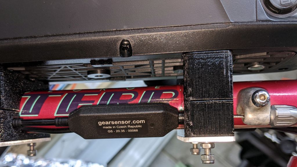
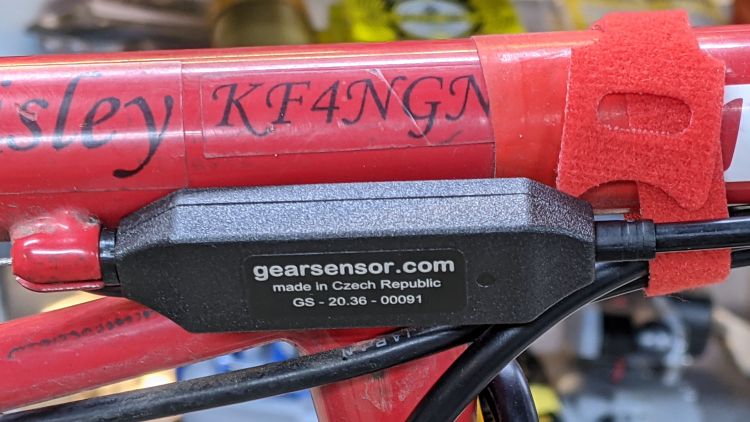
On a typical bike, it mounts against a cable stop with the cable housing holding it in place against its other end:
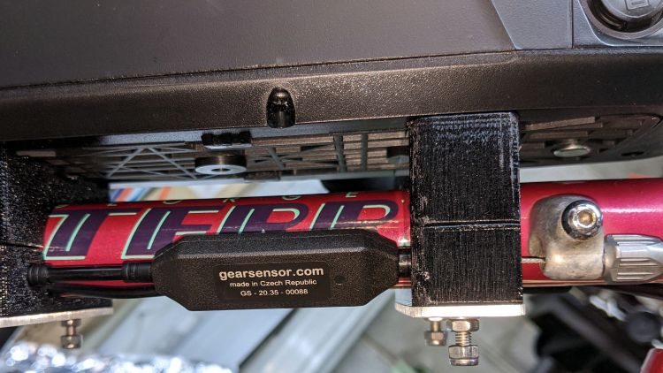
Tour Easy Bafang BBS02 – shift sensor – installed
The Terry Symmetry has only two lengths of housing: in front of the adjuster on the downtube and behind the stop brazed to the chainstay. In either position, the sensor would move as the shift cable flexed and (IMO) put unreasonable stress on the electrical cable running to the motor.
Yes, the Tour Easy has those same two lengths of housing, but the forward one joins a sheaf of wires & cables that barely moves.
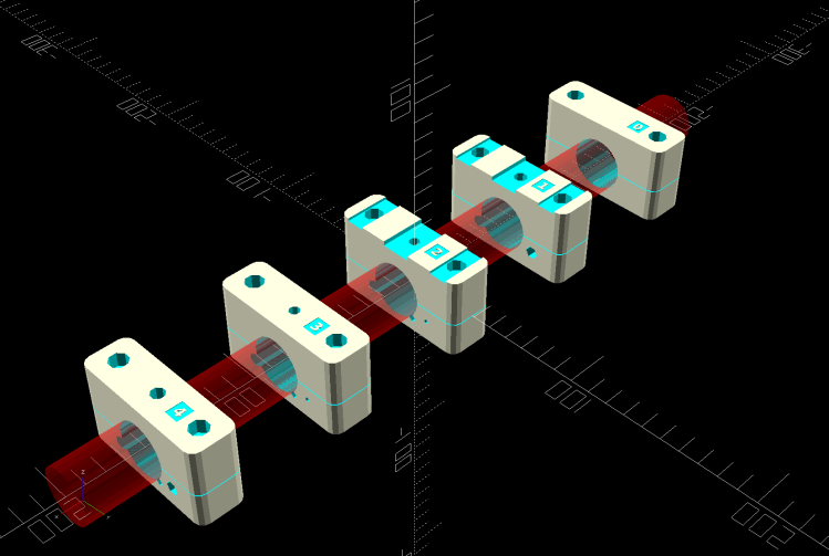
Fortunately, the sensor fits neatly between stations 1 and 2 along the downtube, with a snippet of PTFE lIned housing holding it firmly in place, with the 3D printed battery mounting blocks including paths for both cables:
Terry – Bafang battery – all stations – solid model
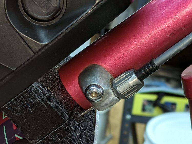
The shift cable originally ran from the adjuster in the front to the guide under the bottom bracket along a slightly diagonal path I could not possibly match. Instead, the path is now parallel to the downtube from the front adjuster:
Terry Bafang – OEM shift stop
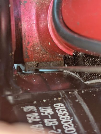
.. to the rear block, where it angles downward over the motor to the bottom bracket:
Terry Bafang – shift cable clearance
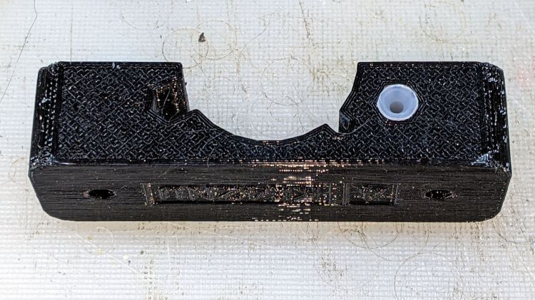
The front block at station 1 has a Delrin / acetal bushing to align the cable with the rest of the blocks:
Terry shift guide – acetal installed
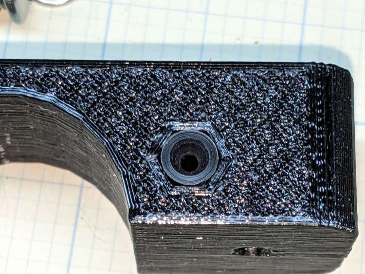
Yes, it’s a round peg jammed in a hexagonal hole:
Terry shift guide – acetal hole
Turning it from stock is well within the capabilities of Tiny Lathe™:
Terry shift guide – acetal cutoff
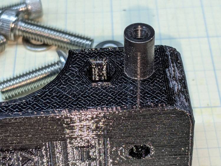
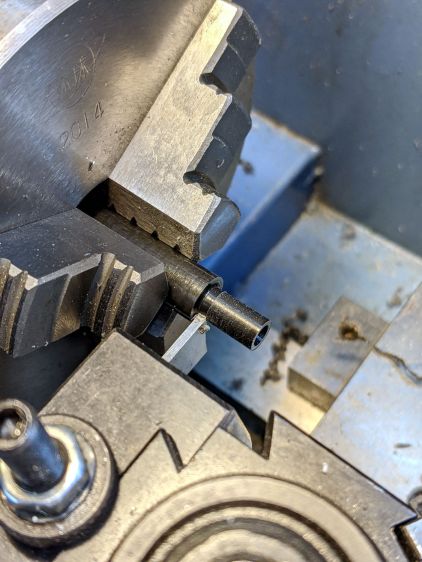
For great slippery, a similar UHMW PE bushing supports the cable bend at the rear of the station 4 block:
Terry shift guide – UHMWPE installed
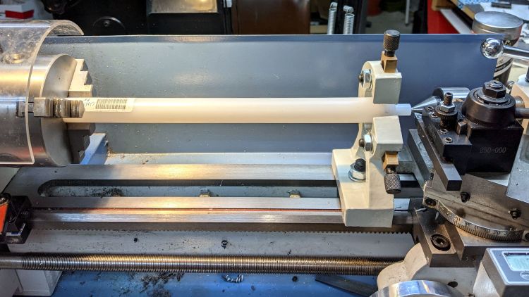
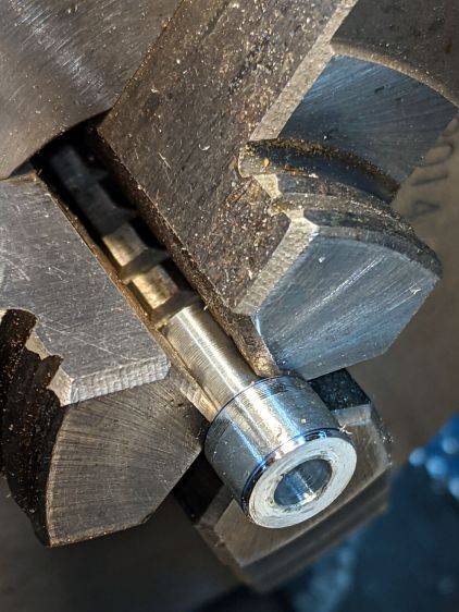
The Basement Laboratory Warehouse Wing disgorged an overly large rod taxing Tiny Lathe™ to its limit:
Terry shift guide – UHMWPE turning
Memo to Self: next time, just saw off a stub and move on.
One of those LED spotlights may have barely outlasted its worthless warranty, but not by much, and has been languishing on the back of the bench with “Flickers hot” scrawled on its side.
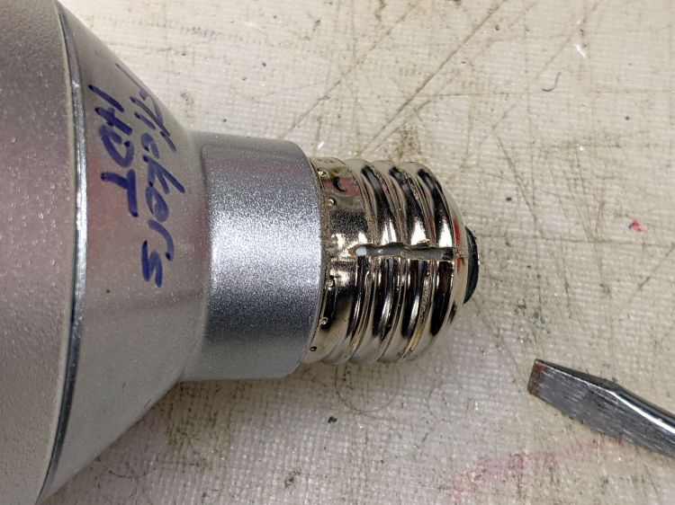
The metal base didn’t respond to twisting, so I slit the threads with a cutoff wheel:
Satco PAR30 – thread slit
Applying the screwdriver removed the base to reveal a silicone rubber casting:
Satco PAR30 – thread silicone
The small wire emerging near the edge of the plastic case seems to be the neutral contact to the shell, with a poor enough joint to suggest it might have been why the lamp flickered when it got hot.
Some brute force snapped the silicone off at the bottom of the plastic case and broke the two wires bringing AC to the PCB:
Satco PAR30 – thread silicone base
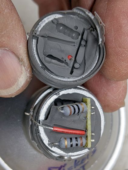
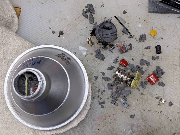
Digging around inside produced a debris field of silicone crumbs, broken resistors, torn caps, and various other components, with zero progress toward removing the shell:
Satco PAR30 – silicone extraction
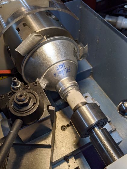
A little lathe work converted a chunk of PVC pipe into a crude mandrel supporting the mangled case:
Satco PAR30 – base cutting setup
A few millimeters of sissy cuts released a silicone O-ring sealing the shell against the reflector:
Satco PAR30 – O-ring seal
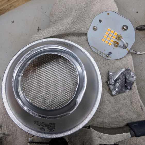
Continuing the cuts eventually revealed the three screws holding the shell to the reflector and the two wires powering the LED:
Satco PAR30 – reflector separated
Chopping off the screws with a diagonal cutter freed the shell and revealed the top of the PCB:
Satco PAR30 – electronics top
It really does have a surprising number of components!
Those three screws connected the LED panel / heatsink to the shell through the back of the double-walled reflector. More brute force peeled the outer shell away and released the panel:
Satco PAR30 – lens assembly
Each of the 5050 packages contains a pair of white LEDs with 5.2 V forward drop for the pair, at the very low test current. They’re all in series, so you’re looking at well over 60 V total forward drop:
Satco PAR30 – LED panel detail
Note that the wiring, which nobody will ever see, follows the electrical color code of white = common and gray = hot.
All the work on Mary’s bike reminded me of the rear fender bracket I meant to install on mine, with more clearance for the strut stabilizing the under-seat packs:
Tour Easy Rear Fender Bracket – long setback – solid model – show
Rather than glue a PETG filament snippet into a screw, I turned a little Delrin plug:
Tour Easy Rear Fender Bracket – screw insert
It’s ready for installation when I’m willing to put the bike up on the rack and pull the rear wheel:
Tour Easy Rear Fender Bracket – screw detail
That’s actually the second iteration for the screw, as the first suffered a lethal encounter with the Greater Shopvac. I know exactly where it is, but I’m not going there …
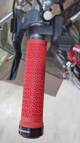
Installing the Bafang BBS02 motor on Mary’s Tour Easy replaced the triple chainring, so I removed the front derailleur and SRAM grip shifter. This produced enough room for the thumb throttle and a full-length handgrip on the left side:
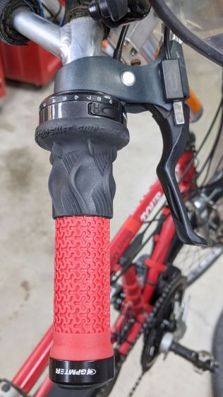
The right handlebar still has the rear shifter, so it requires a shorter grip:
Tour Easy grips – right installed
Although it may be possible to buy such a grip and, thereby, get a backup pair of mismatched grips, it seemed easier straightforward to just shorten the grip to the correct length and be done with it.
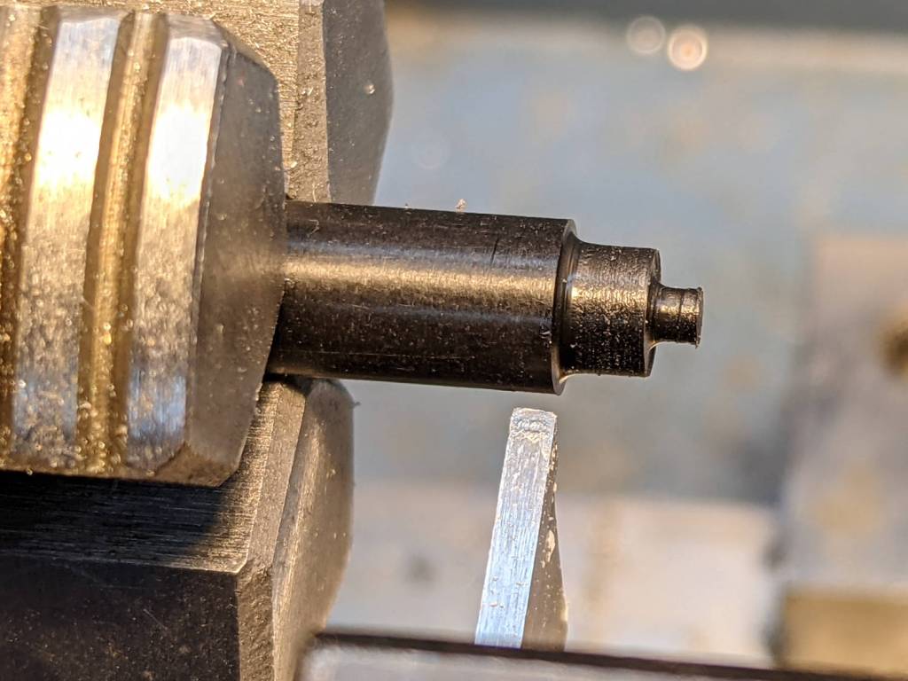
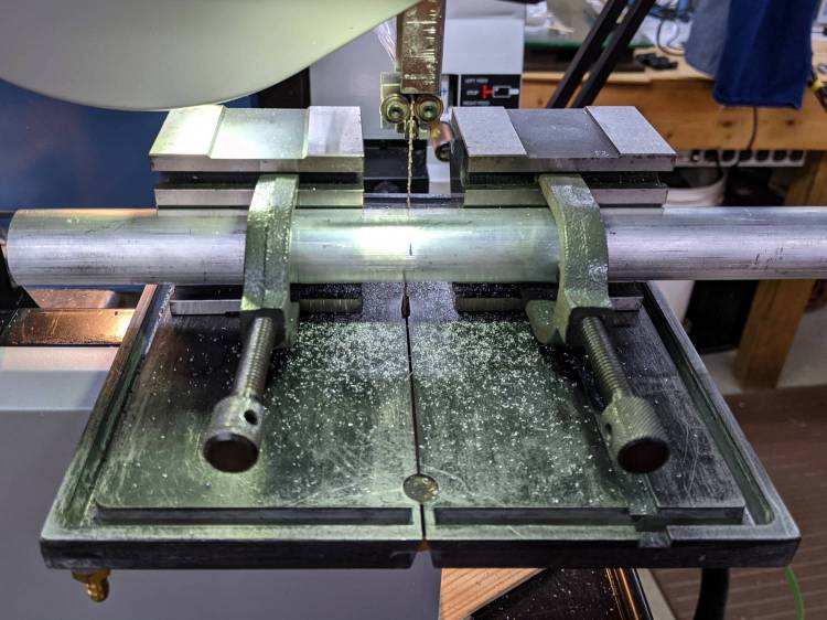
Saw off a convenient length of aluminum rod:
Tour Easy grips – mandrel sawing
Although I actually used a steady rest to produce this, it happened during a remote Squidwrench meeting and I have no proof:
Tour Easy grips – lathe mandrel
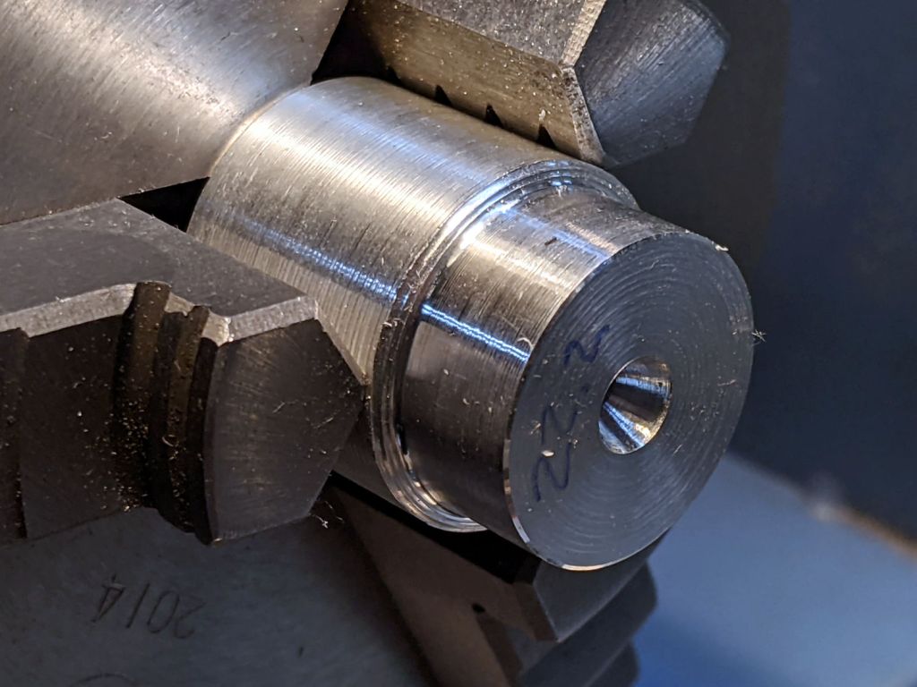
The 22.2 mm = 7/8 inch end matches the more-or-less standard handlebar diameter, so the grip clamp can get a good hold:
Tour Easy grips – right peeled
A live center supports the right end of the grip.
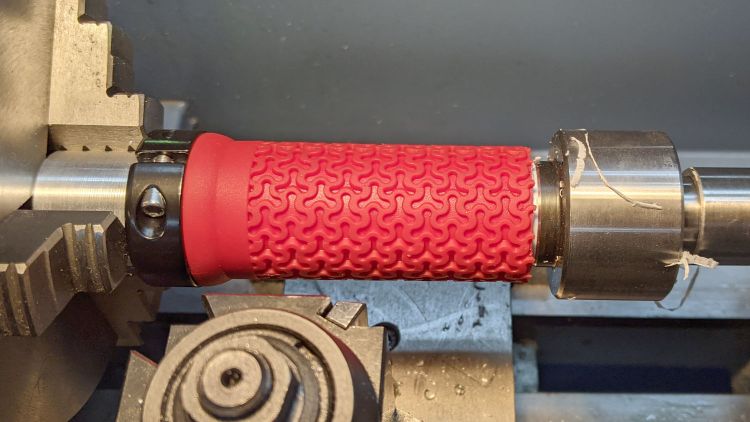
The red coating seems to be gooey silicone rubber molded atop a PVC tube. Rather than (try to) use a lathe bit to cut through the silicone, I cut two slits with a utility knife and the spindle turning slowly in reverse, then peeled off the rubber between the slits.
With the silicone out of the way, an ordinary cutoff tool made short work of the PVC:
Tour Easy grips – right trimming
That was a cleanup pass with the utility knife, as the cutoff tool left a slight flange around part of the circumference. If I had the courage of my convictions, I could probably have cut the PVC with the knife.
Chamfer the end of the cut, slide it on the handlebar, tighten the clamp, and it’s all good.
The alert reader will note the clamp should go on first, but that would produce an inconvenient lump against the right shifter. Sliding them on backwards puts the clamp at the end of the handlebar and works out better in this admittedly unusual situation.
Contemplating a project using a small saw in the Sherline suggested that attaching the workpiece to the side of a 123 block would simplify the machining. My blocks have a centered quintet of 3/8-16 tapped holes through the 2×3 side, all the remaining holes are untapped, and it has no smaller holes. The hole spacing doesn’t match the Sherline tooling plate, but the T-nut slots in the underlying table would suffice.
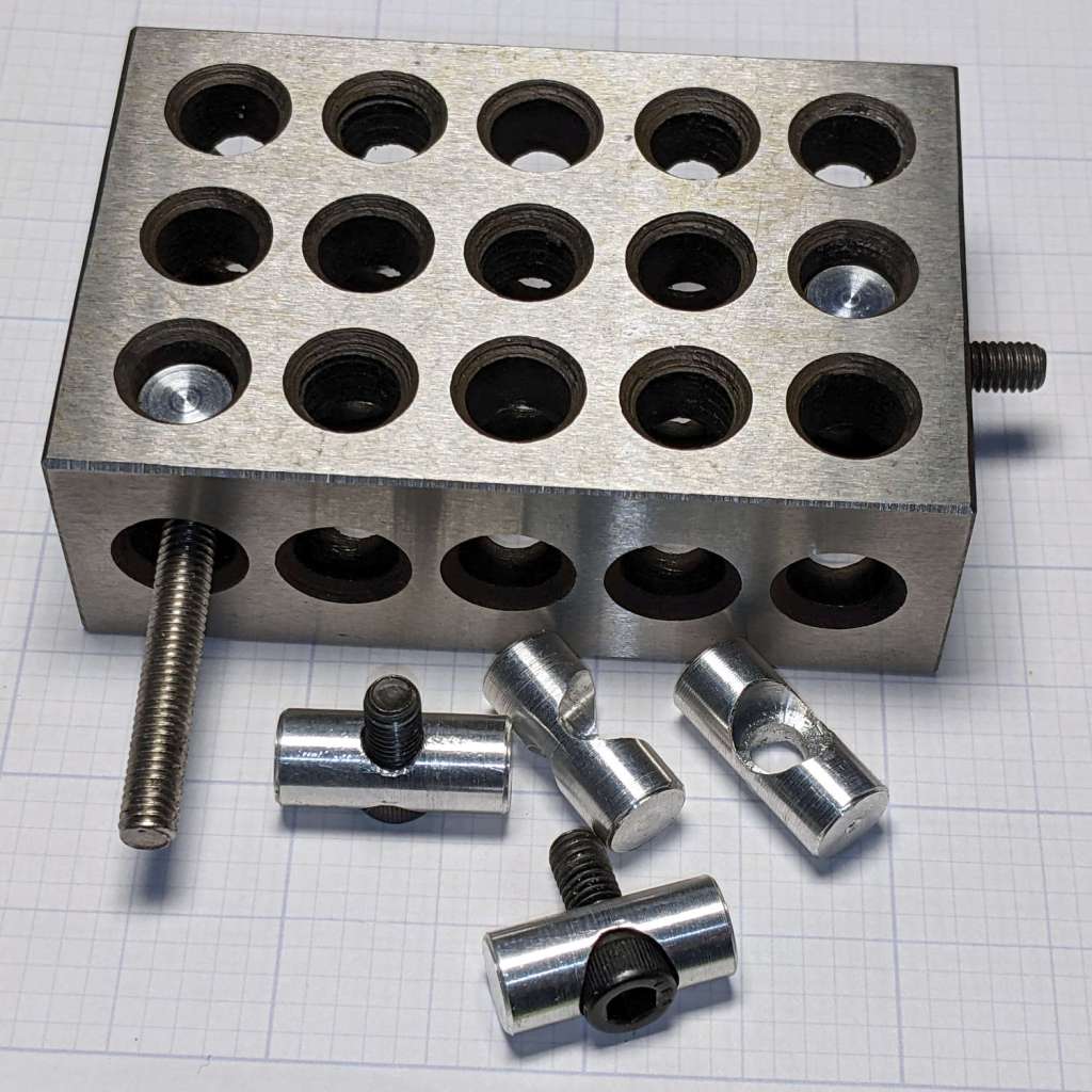
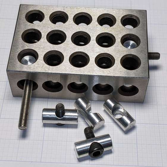
Rather than run long 10-32 screws through the entire block, It Would Be Nice to use short screws from, say, the nearest holes:
123 Block Links – assembled
I cannot possibly be the first person to have this idea, but the obvious keywords don’t produce any useful results on The Intertubes, other than a link to a different (and far more complex) block with counterbored holes of various sizes.
The holes through the blocks probably came from a 5/16 inch drill, the 75% thread depth diameter for the 3/8-16 taps used on the threaded holes. They’re distorted, full of debris, and hardened enough to kill a file, so I eventually settled on 8.2 mm pins that pass through most of the holes.
The socket head screws seat at the pin axis, because the pin diameter is scary close to the counterbore diameter and I didn’t see much point in finesse. I started with a half-inch aluminum rod and peeled it to size, because it simplified the clamping and I have a bunch of them.
The pins are 3/4 inch long to leave a little space on either side of the 1 inch deep holes. I started with comfort marks along the length of the rod:
123 Block Links – laser alignment
Center-drill so the clearance drill doesn’t skitter off the top:
123 Block Links – center drilling
The counterbore calls for a 0.204 inch = #6 drill, just slightly larger than the #7 clearance drill for a 10-32 screw:
123 Block Links – counterbore
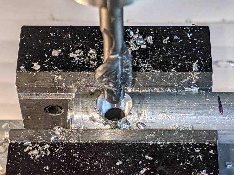
I touched off the counterbore flutes on the sides of the hole, then drilled downward half the 12.8 mm actual rod diameter:
123 Block Links – 10-32 SHCS test fit
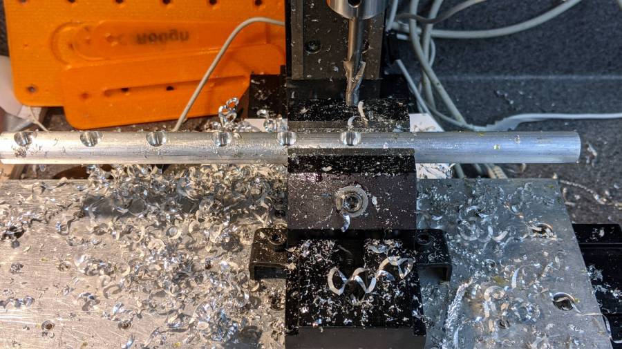
Lower the counterbore into the hole again, relax the vise enough to let the rod slide, jog the spindle to X = -25.4 mm, and tighten the vise again:
123 Block Links – index setup
I figured I needed four pins, tops, so make half a dozen to be sure:
123 Block Links – all c-bored
Stick the rod in the mini-lathe chuck, add some comfort marks, and prepare to peel it down to 8.2 mm:
123 Block Links – lathe setup
Having done the lathe work during a Squidwrench remote meeting, I have no pictures of the process, but it goes a little something like this:
Peel off 0.5 mm at a time, stopping just beyond the mark on the left
Mark 3/8 inch on each side of the hole center
Face the end
Chamfer the rim with a file
Clean up the body hole and counterbore
Part the pin off a bit to the left of the mark
Remove the rod
Chuck the pin with the cut off end outward
Face to the mark
Chamfer
Repeat for all six pins
Done!
It’s tedious, but not particularly difficult.
Futher doodling suggested the need for threaded pins to join two blocks together.
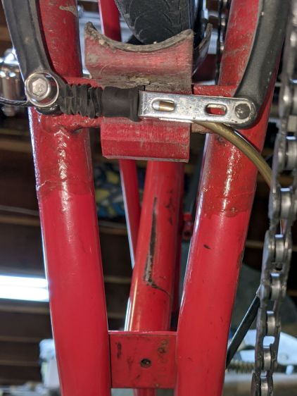
Although our Tour Easy recumbents use ordinary (*) V-brakes, their frame geometry doesn’t route the rear cable quite the way the brake designers expected. Mary’s Medium-Small frame always had its rear brake cable resting against the frame tube, where it bent slightly as she applied the brakes:
Tour Easy rear V-brake layout
That’s looking up from under the rear wheel, with the bike on a workstand, and, yeah, it’s pretty grubby down there.
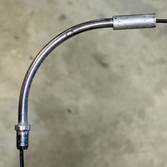
The squashed rubber boot suggests the brake arms are too close together, but that’s where they must be to hold the brake pads in the proper position, even with new pads and big spacer washers. As a result, the cable stop over on the right at the end of the noodle rests against the frame and dings the paint.
My first thought was to add some length to the end of the noodle inside the stirrup, so I made an adapter with the ID on the noodle end matching the OD on the fitting end:
V-brake – larger noodle – end stop adapter
Which worked poorly, because the noodle has a straight section leading up to the fitting inside the stirrup; any additional length pushes the noodle curve against the stirrup pivot and cants it out of line:
Tour Easy rear V-brake noodle
I’ve been avoiding the fallback plan of building a bigger noodle for years, but finally combined a foot of 3/32 inch brass tubing, a tube bender spring, and various large-diameter round-ish objects from the Basement Warehouse Wing:
V-brake – larger noodle – bending
I annealed the tube by running a torch along its length until the color changed to the obvious “I’m hot enough” copper color, then let it air-cool while I did something else. Brass work-hardens quickly and required two more annealings while finishing that smooth curve; as far as I know, brass doesn’t harden with the heat-and-quench cycle used for steel.
A little more lathe work produced a replacement fitting:
V-brake – larger noodle – end stop
The hole is barely one diameter deep, but I think it’ll align the tube well enough for my simple needs. The failure will most likely involve having the cable chew through the inward side of the mis-aligned tube, which should become obvious in short order.
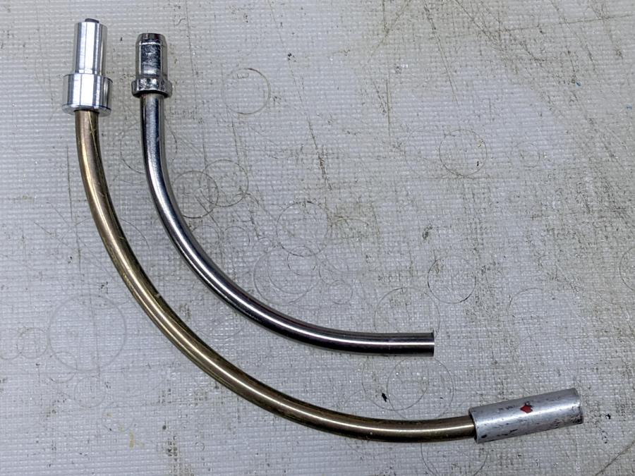
The fitting on the OEM noodle seems to be crimped in place, but I figure my version is unlikely to fall off in normal use:
V-brake – larger noodle vs OEM
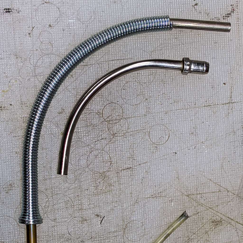
Lined up thusly, you can see the reduced straight section behind my fitting and the much larger sweep out to the cable stop.
The OEM noodle had a (presumably) PTFE liner, so I adapted a length of PTFE brake cable liner by mashing the end with various conical objects until it kinda-sorta looked like the cable stop might capture the ragged flange:
V-brake – larger noodle – PTFE liner
Reassembling in reverse order produces a comforting sight:
V-brake – larger noodle – installed
Despite appearances, the new noodle sits below the frame and well above the chain in normal use. In the most extreme small-small cross gearing position the chain barely clears it, but the takeup arm on the rear derailleur starts clattering enough to remind us not to do that.
Brass is certainly not as strong as stainless (?) steel, although I think it ended up in a reasonably hard condition after all the bending. I’m certain neither of us can squeeze the brake lever enough to come anywhere close to causing a problem.
Making a noodle was easier than I expected and, in a month or so, we’ll see how it behaves under actual riding conditions.
(*) “Ordinary” as of many decades ago, because the design dates back to the mid-70s, when Fast Freddy Markham broke 65 mph on a rather customized Easy Racers Gold Rush.
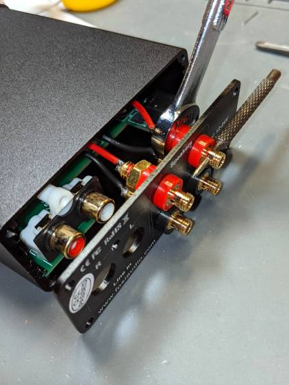
A low-end audio power amp destined for a pair of ancient-yet-still-serviceable speakers arrived, but attempting to poke wires through the side holes of the banana jacks showed they were oriented in random directions. Back in the day, banana jacks had D-shaped shafts fitted into D-shaped panel holes, but those days are gone.
A few minutes with screwdriver, wrench, and (tiny) punch sufficed to line up the holes for E-Z poking:
Fosi audio amp – jack alignment
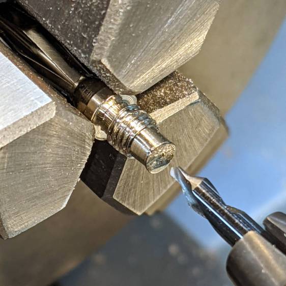
Despite the new convenience, I decided to solder banana plugs to the speaker wires, leading to the discovery my few remaining plugs came from the very bottom of the usability barrel:
Cheap banana plug – solder side
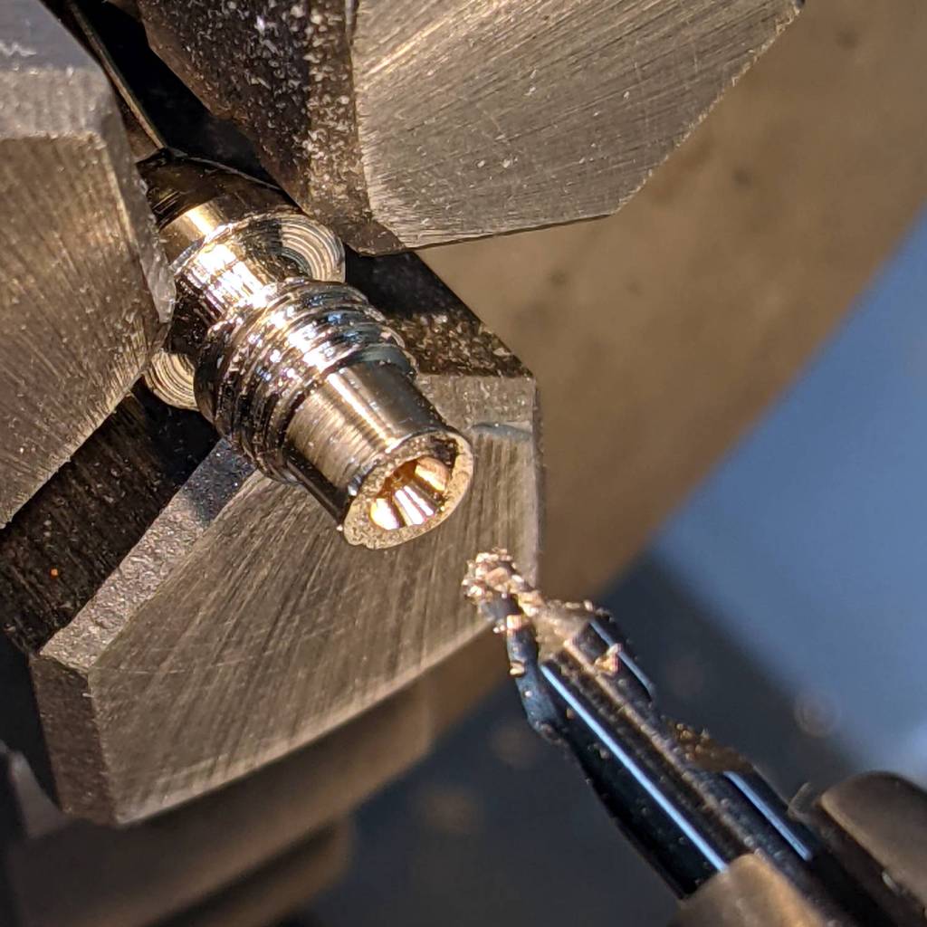
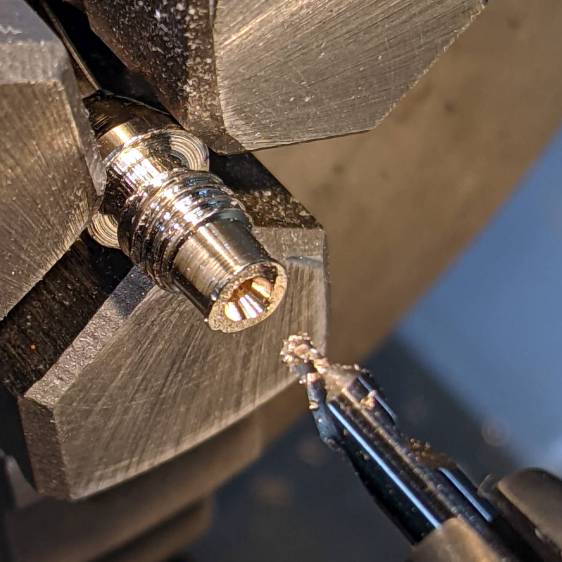
I have no idea how one might affix a wire to that blank stub, but poking a small center drill into the brass lump produces an easily solderable recess:
Cheap banana plug – center drilled
Dab with flux, tin, insert wire, add solder, repeat with all four plugs, and I’m set with a boomin’ system.