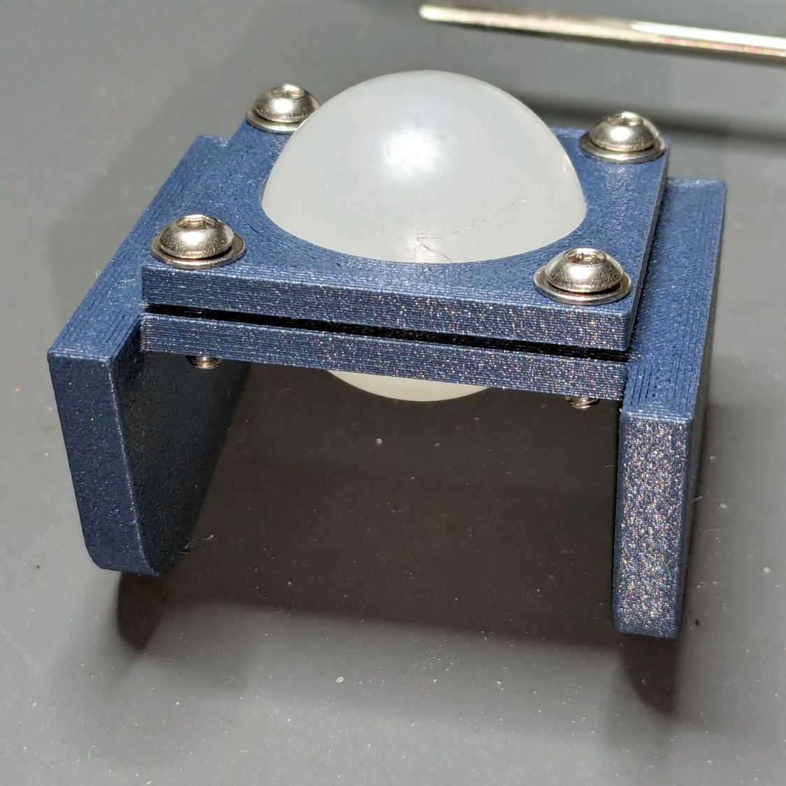
With the ball mount in hand:
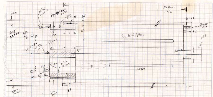
The next step is to drill a 12 mm hole for the red-dot laser module right through the middle of the 1 inch = 25.4 mm polypropylene ball.
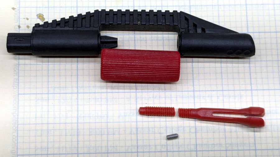
I decided to use a more-or-less standard laser module, rather than the Genuine Handi-Quilter laser, because:
- Cheap & readily available
- Identical spares on hand
- Two decades of red laser diode progress
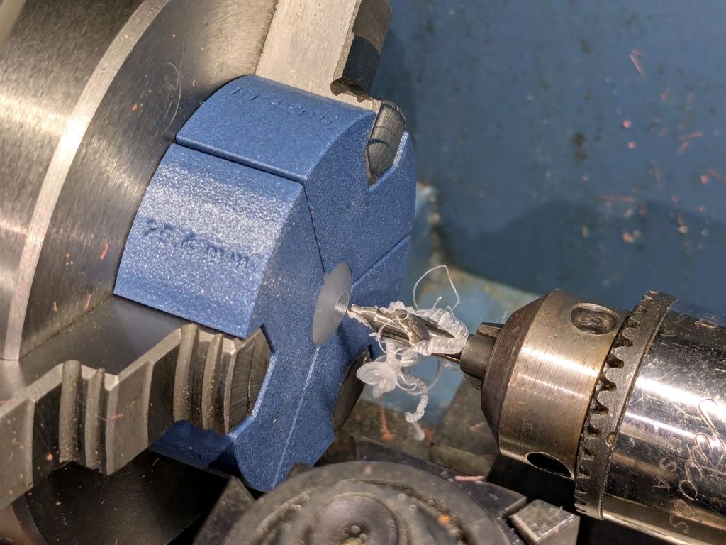
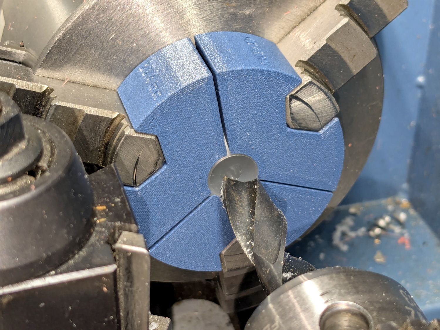
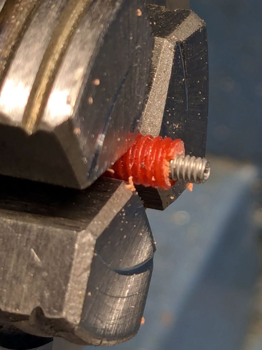
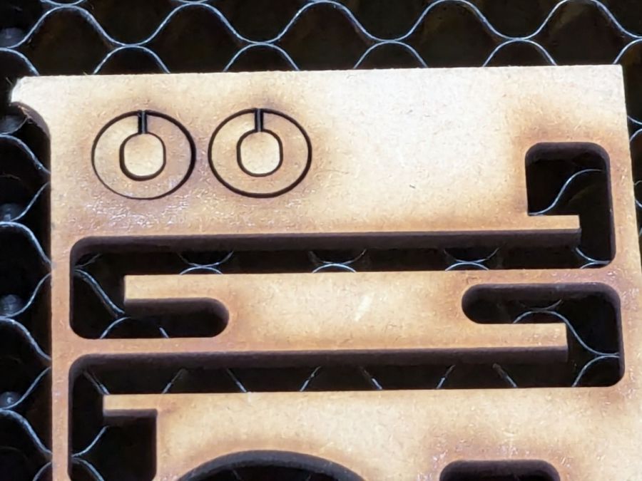
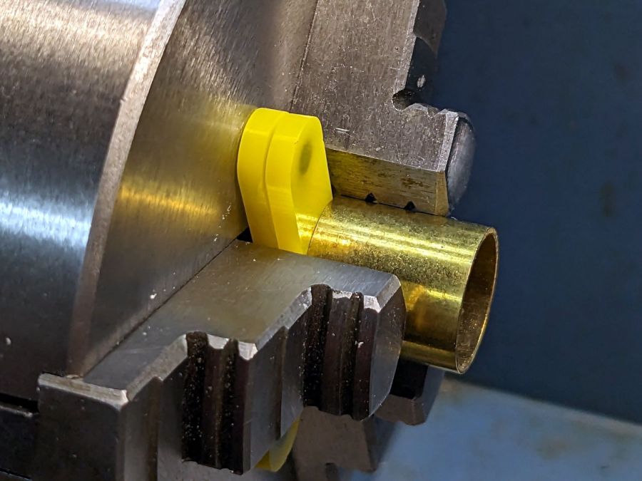
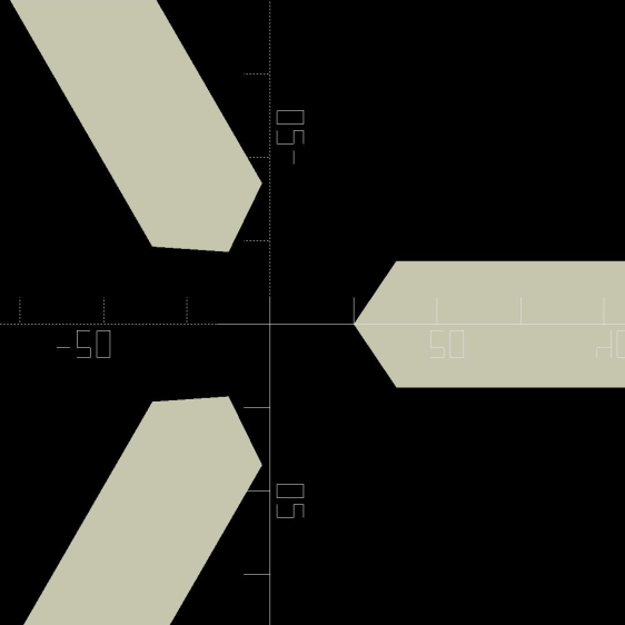
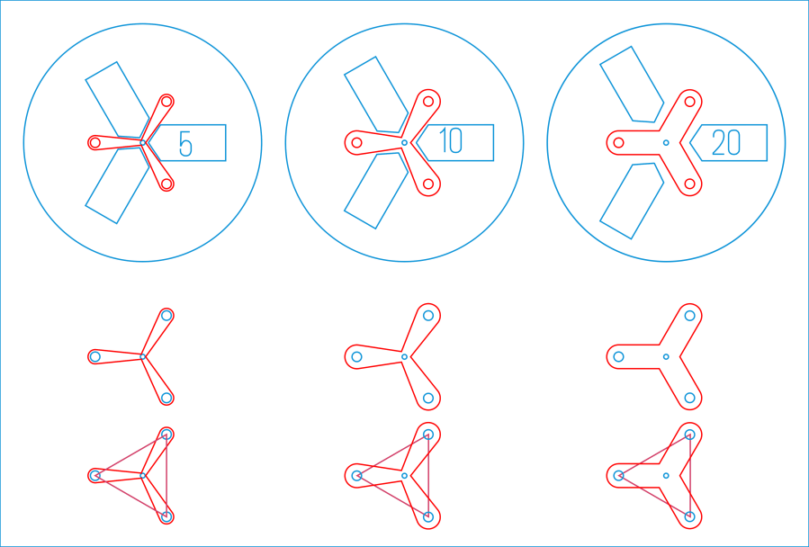
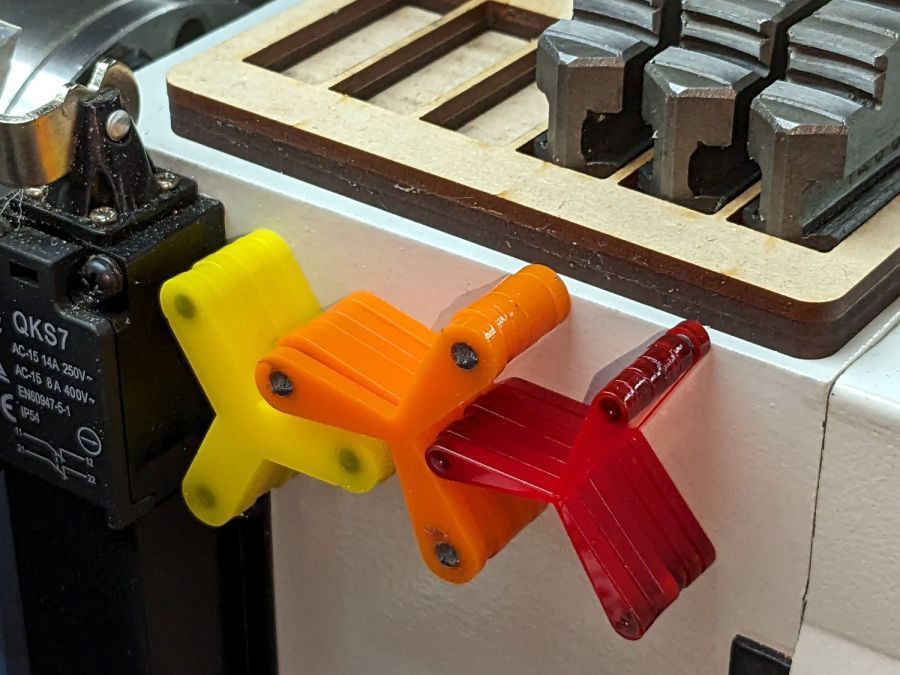
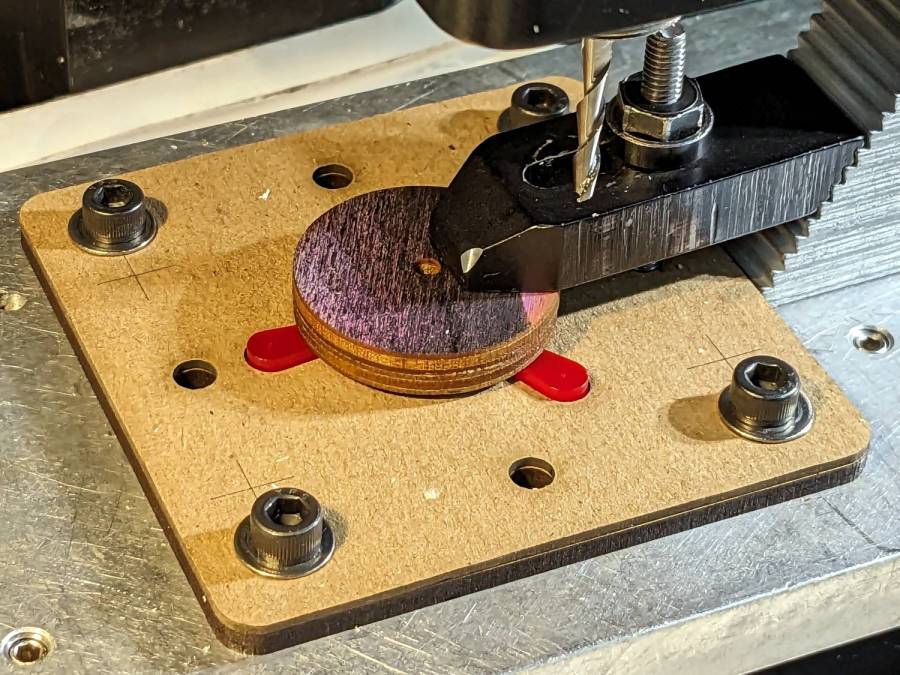
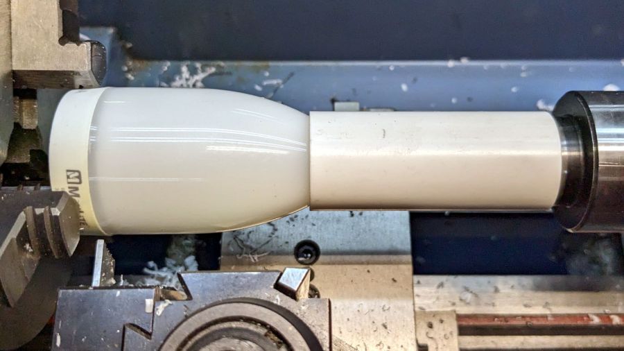
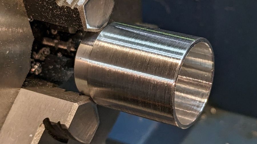
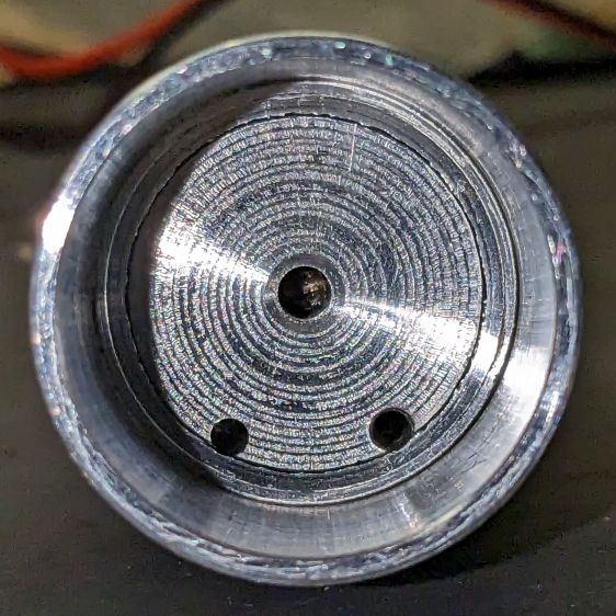
Start by conjuring a lathe chuck fixture for a 1 inch ball from my OpenSCAD model and printing it in PETG-CF:

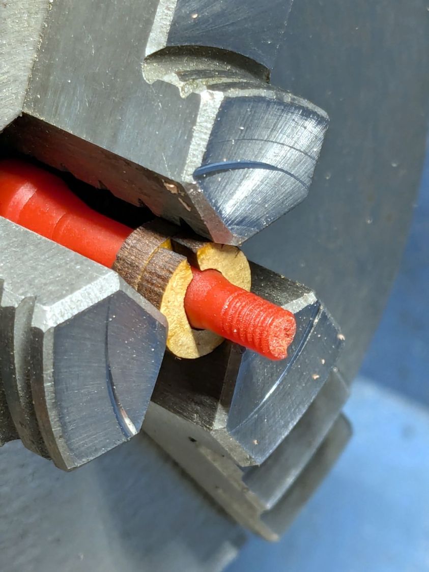
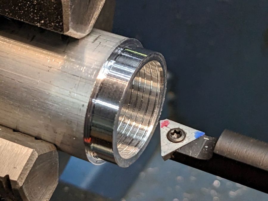
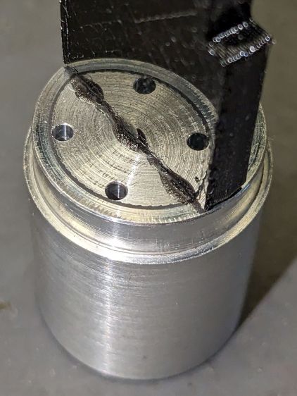
Run a few drills through the ball up to 15/32 inch = 0.469 inch = 11.9 mm:
Which looks terrifying and was no big deal.
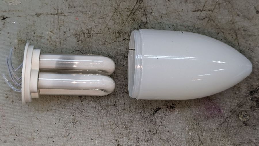
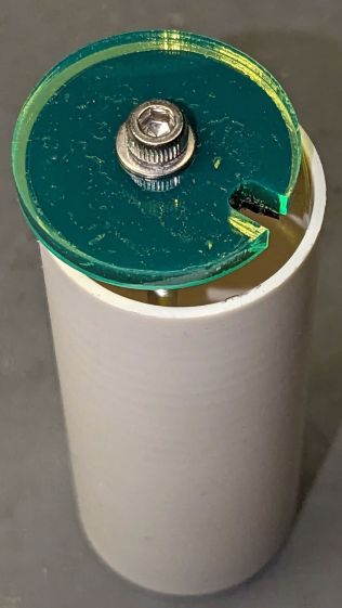
The laser module didn’t quite fit until I peeled off the label, as setting up a boring bar seemed like too much hassle for too little gain. The ball is slick polypropylene and the laser module is chromed plastic, which means there’s not much friction involved and a stiff fit is a Good Thing™.
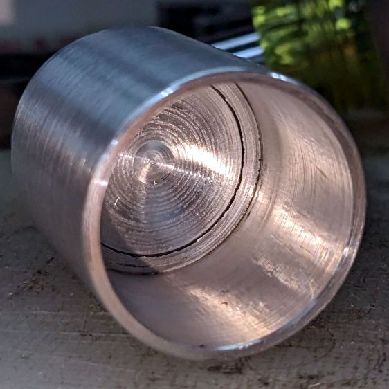
I did not realize the hazy white patches barely visible inside the ball were voids / bubbles:
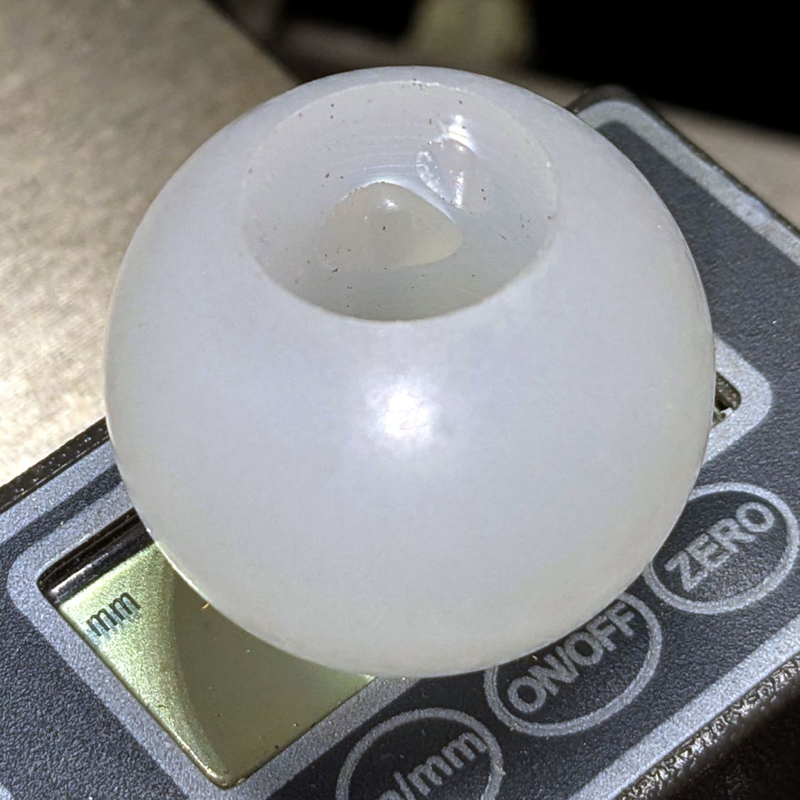
Next time I’ll (try to) orient the patches toward the tailstock in hopes of simply drilling through them to leave solid plastic around the rim.
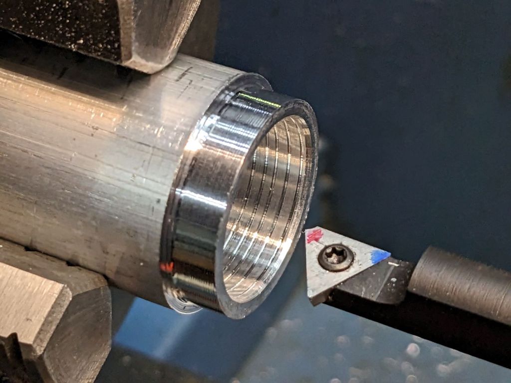
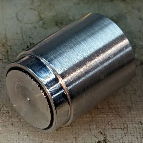
Ramming the laser in place makes it look like it grew there;
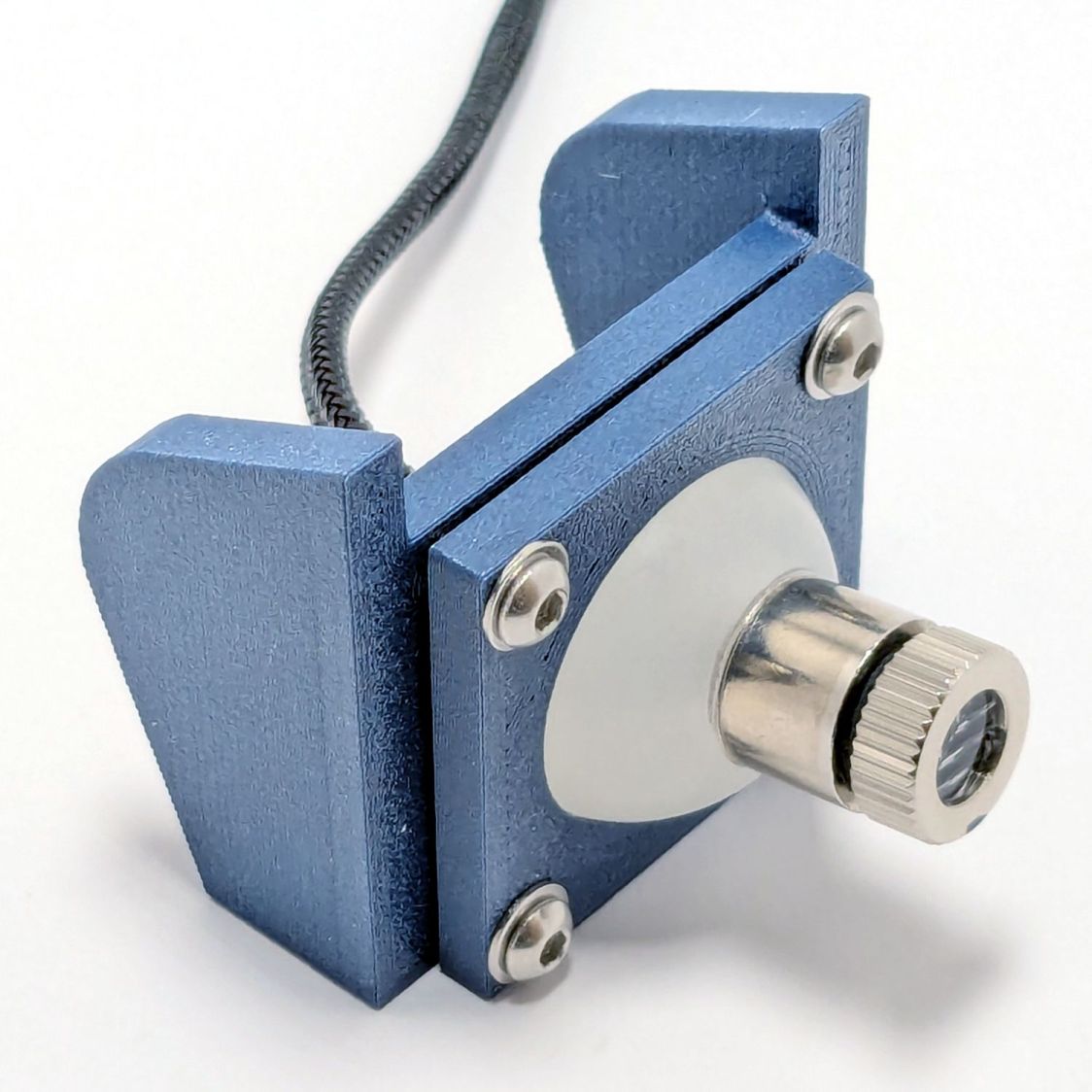
The alert reader will note the lens projects a line, due to my not ordering any dot modules back when I got a bunch of these things. After all, who wants a plain dot when you can light up a line or even a crosshair?
Next, wire it up and stick it on the machine …


