Ed Nisley's Blog: Shop notes, electronics, firmware, machinery, 3D printing, laser cuttery, and curiosities. Contents: 100% human thinking, 0% AI slop.
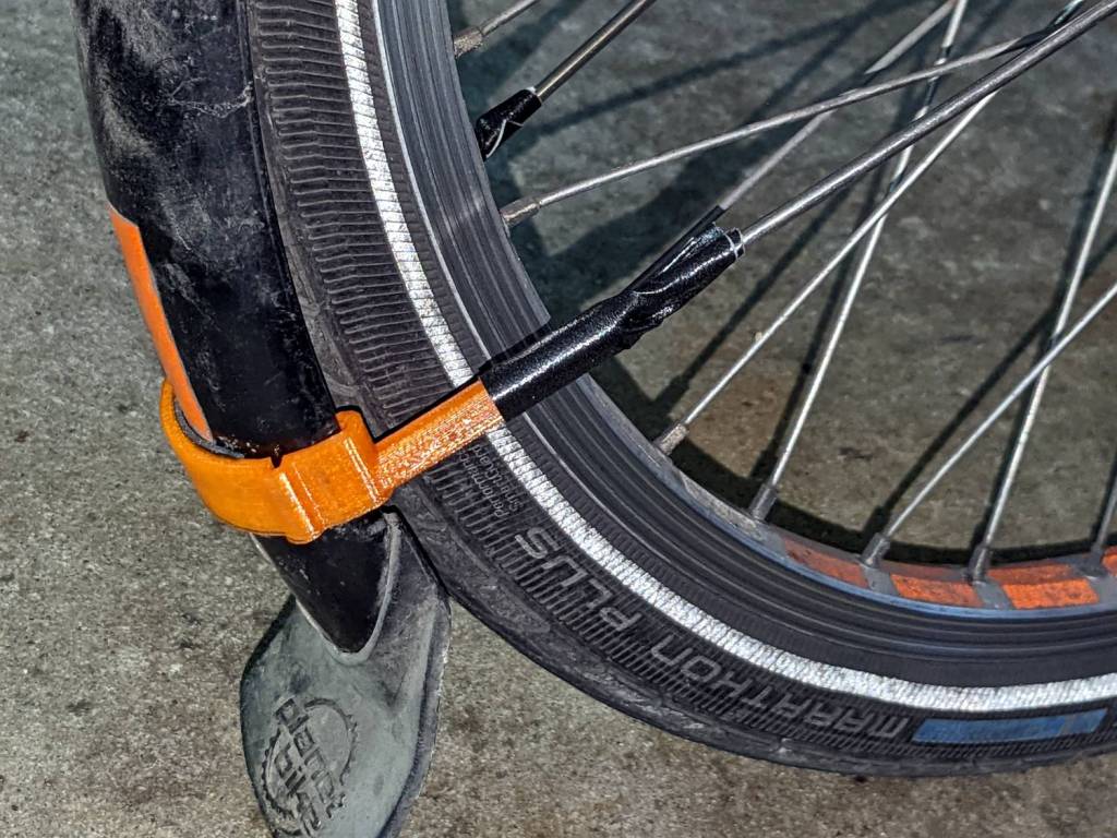
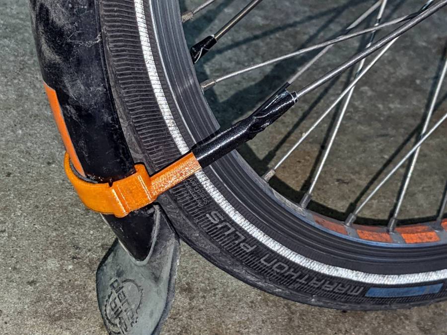
The mudflap on my front fender rides low enough to snag on obstacles and the most recent incident (about which more later) was a doozy, breaking the left strut ferrule and pulling the bracket off its double-sticky foam tape attachment. Fortunately, the repair kit now has plenty of duct tape.
Applying a laser cutter to paper-like materials requires balancing two contradictory imperatives:
Hold the sheet flat to avoid distortions
Have nothing below to avoid schmutz on the bottom
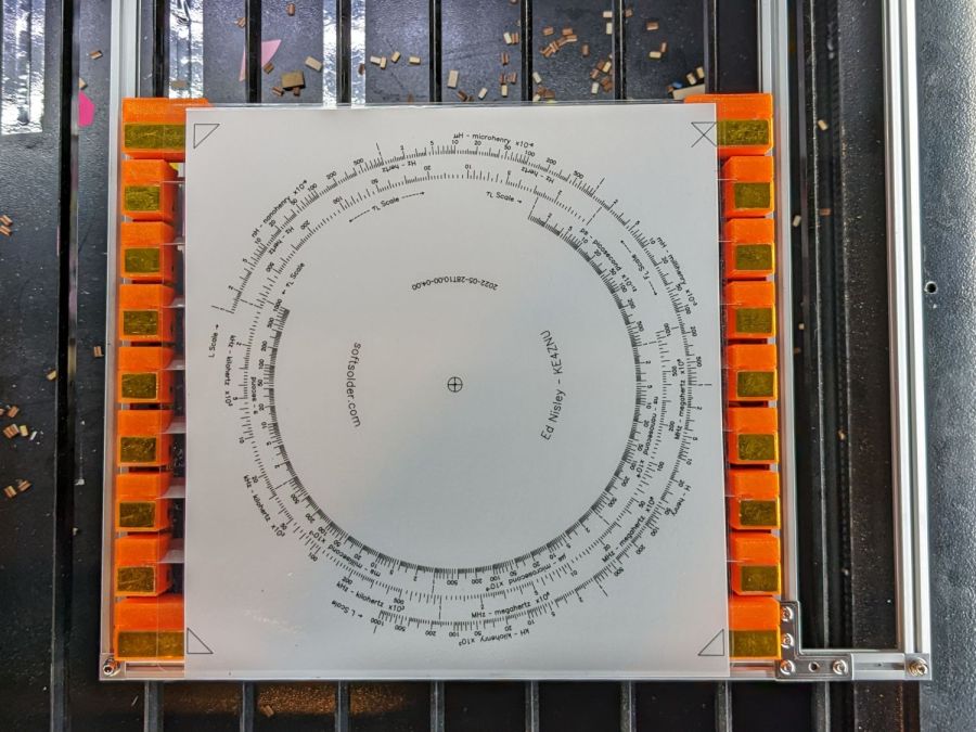
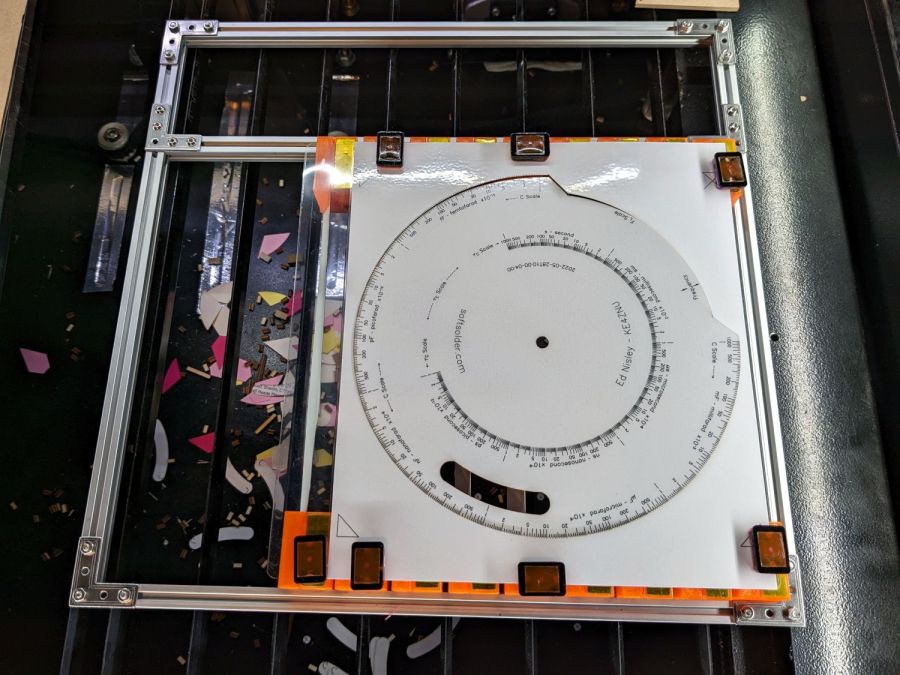
This seemed like a good compromise:
Sheet Holder – Tek CC bottom deck
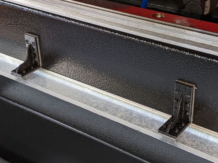
The orange 3D printed blocks hold aluminum miniblind blades:
Sheet Holder – steel sheet magnet pads
The curved slots hold the blades flush with the upper surface and align their top sides parallel to the laser beam, giving the beam very little blade to chew on near the focus point and allowing plenty of room below the sheet to dissipate cutting fumes.
The gold-ish squares are thin steel sheets covered with Kapton tape, painstakingly filed en masse from small snippets:
Sheet Holder – filed steel pads
The first iteration used precisely laser-cut refrigerator magnet pieces, in the expectation a crappy rubber magnet would provide just enough attraction to let a neodymium magnets hold the paper flat, without risk of blood blisters between fingers and steel:
Sheet Holder – ferrite magnet pads
As expected, contact with the neo magnet completely wiped away the alternating pole magnetism in the rubber sheet, leaving a weakly attractive non-metallic surface. Alas, the rubber had too little attraction through a laminated sheet of paper, so I switched to real steel and risked the blisters.
Most of the blocks are narrow:
Sheet Holder Bracket – solid model
The four corners are wider:
Sheet Holder Bracket – wide – solid model
They’re symmetric for simplicity, with recesses for the magnets / steel sheets on the top. The through-holes have recesses for M3 SHCS holding them to T-nuts in Makerbeam rails, with a slightly overhanging alignment ledge keeping them perpendicular to the rail.
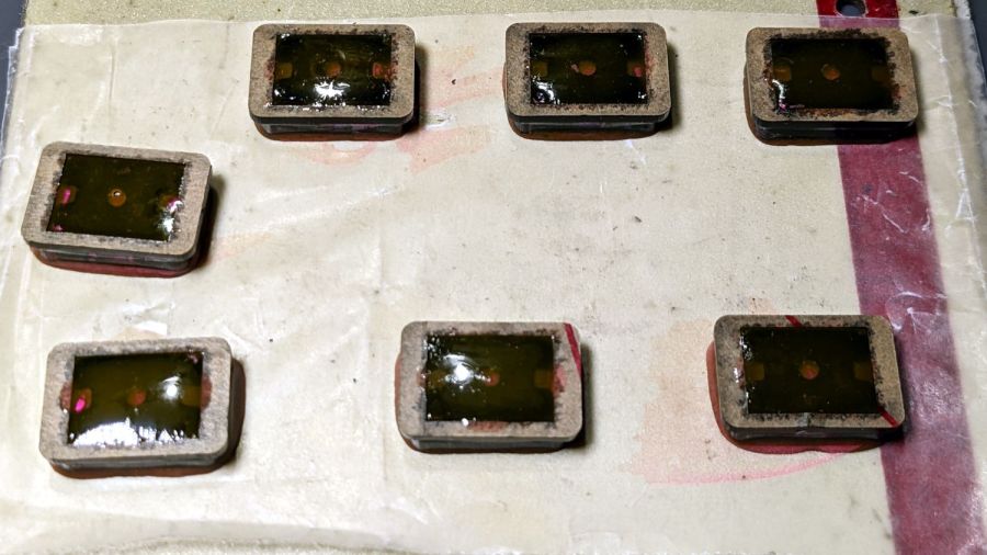
The magnets come from an array of worn-out Philips Sonicare toothbrush heads:
Sheet Holder – magnet holders curing
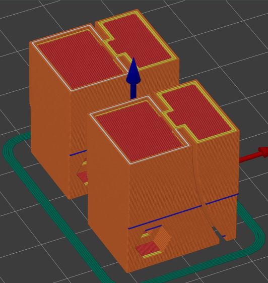
They’re epoxied inside a two-piece mount, with the lower part laser-machined from 3 mm acrylic to put the two magnets in each assembly flush with the lower surface; the green area gets engraved 1 mm below the surface for the steel backing plate. The 1.5 mm upper frame fits around the plate and protrudes over the ends just enough for a fingernail grip:
Magnet Holder Cuts
The epoxy got a few drops of fuschia dye, because why not:
Sheet Holder – trimmed magnet holders
The garish trimmings came from slicing the meniscus around the lower part of the holder off while the epoxy was still flexy.
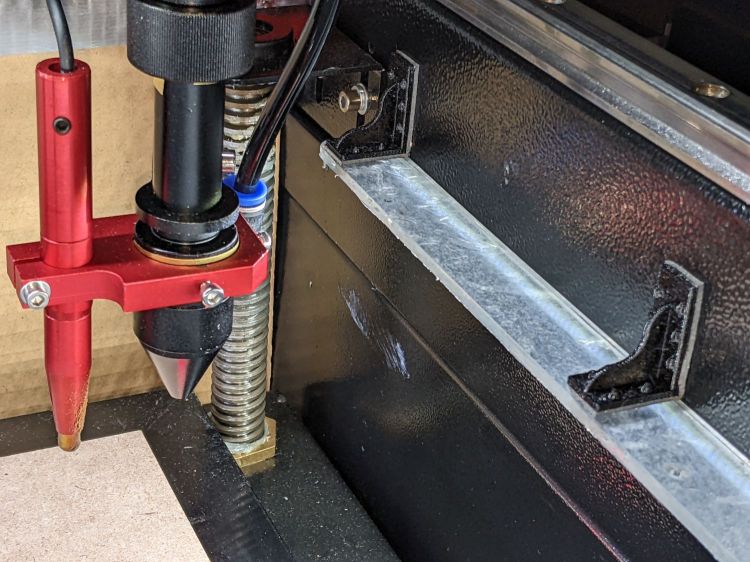
The holders must be flat for clearance under the focus pen:
Sheet Holder – focus probe clearance
Some experimentation suggests I can raise the pen by maybe 2 mm (with a corresponding increase in the Home Offset distance) , but the switch travel requires nearly all of the protruding brass-colored tip and there’s not much clearance under the nozzle at the trip point.
With all that in hand, it works fairly well:
Sheet Holder – Tek CC cutout
The lower deck has very little margin for gripping, which is why the four corner blocks must be a bit wider than the others.
The lamInator tends to curl the sheets around their width, so most of the clamping force should be along the upper and lower edges to remove the curl at the ends. This requires turning the whole affair sideways and deploying more magnets, which is possible for the smaller middle and upper decks:
Sheet Holder – Tek CC middle deck
Protruding SHCS heads on the four corners snug up against the edge of the knife-edge bed opening for Good Enough™ angular alignment.
Plain paper (anything non-laminated) seems generally flat enough to require no more than the corner magnets.
It’s definitely better than the honeycomb surface for fume control!
This file contains hidden or bidirectional Unicode text that may be interpreted or compiled differently than what appears below. To review, open the file in an editor that reveals hidden Unicode characters.
Learn more about bidirectional Unicode characters
A little more than two years after replacing its internal battery, the SJCAM M20 camera on my Tour Easy once again wouldn’t last to the end of the driveway if I forgot to turn on the external battery pack. This time around, the camera was so firmly jammed in the printed seat frame mount that I had to cut the mount apart.
Yup, that puppy is all swoll up:
SJCAM M20 swollen battery – side view
Poor thing looks like a tiny pillow:
SJCAM M20 swollen battery – pouch
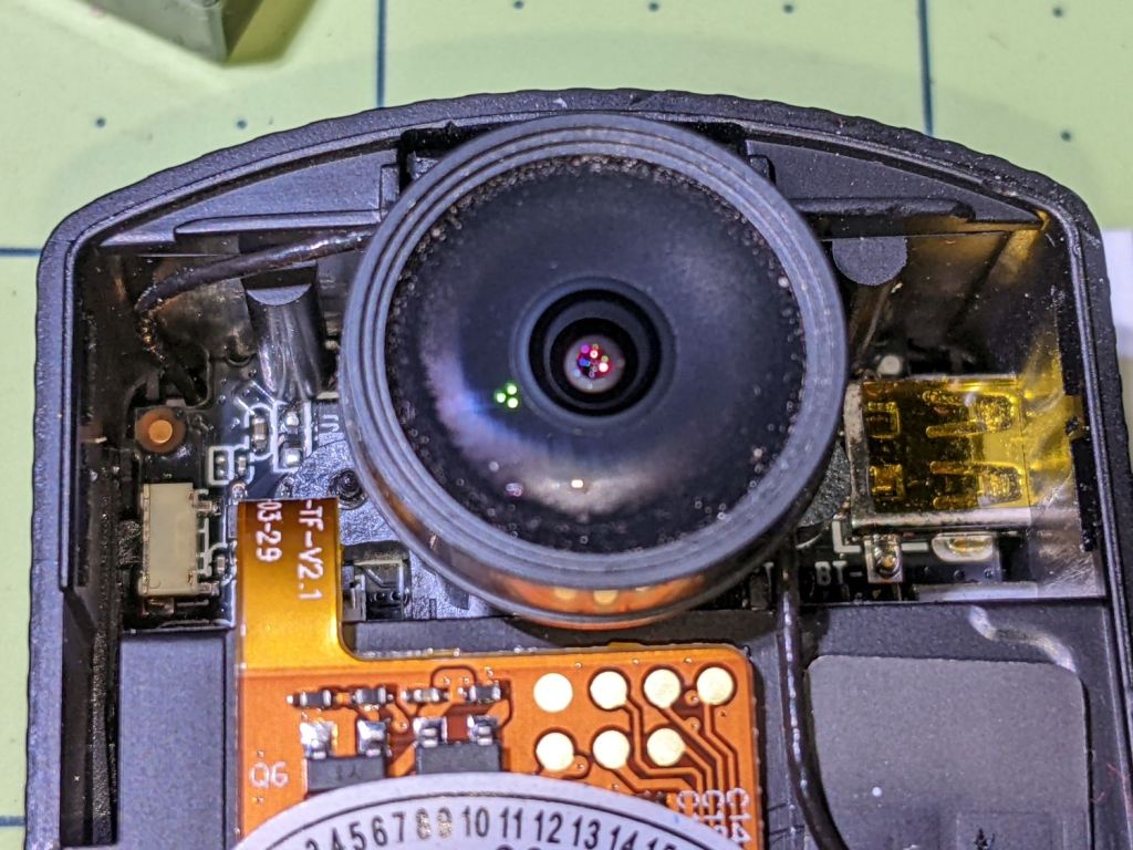
While I had it apart, I tried to clean / refurbish the button contacts on the top. Unfortunately, they’re pretty well buried in the camera frame and I was unwilling to dismantle the optics, remove the display, and gut the camera to find out if they were more accessible from the back surface:
SJCAM M20 – switch internals
While all that was going on, I ran off a new mount in white PETG:
SJCAM M20 – white case installed
I’m down to the last battery. The “4.35V” on the pillow indicates they’re special high-voltage lithium-polymer cells, so I can’t just drop a random lithium pouch cell in there and expect it to Just Work.
I think the “782633” is the cell size, so, if I were willing to have a few thousand on the shelf, a 552525 pouch might fit. The reduced capacity wouldn’t be a problem, as it must just keep the camera’s clock ticking between rides.
TIL: Muntin, which I’d always known was called a Mullion.
With that as preface, one of Mary’s quilting cronies lives in a very old house updated with vinyl windows sporting wood muntins arranged in a grille. The wood strips forming the grille end in plastic clips that snap into the sash, thereby holding the grill in place to make the window look more-or-less historically correct, while not being a dead loss as far as winter heating goes.
Time passed, sun-drenched plastic became brittle, and eventually enough clips broke that the grilles fell out. An afternoon quilting bee produced a question about the possibility of making a 3D printed clip, as the original manufacturer is either defunct or no longer offers that particular style of clip as a replacement part.
Well, I can do that:
Window Muntin Clips
The original is (obviously) the transparent injection-molded part in the upper left. The other two come hot off the M2’s platform, with the one on the right showing the support material under the sash pin.
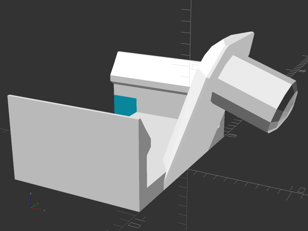
The solid model looks about like you’d expect:
Window Muntin Clip – solid model
There is obviously no way to build it without support material, so I painted the bottom facet of the sash pin with a PrusaSlicer support enforcer:
Window Muntin Clip – PrusaSlicer
The pin comes out slightly elongated top-to-bottom, but it’s still within the tolerances of the original part and ought to pop right into the sash. We’ll know how well it works shortly after the next quilting bee.
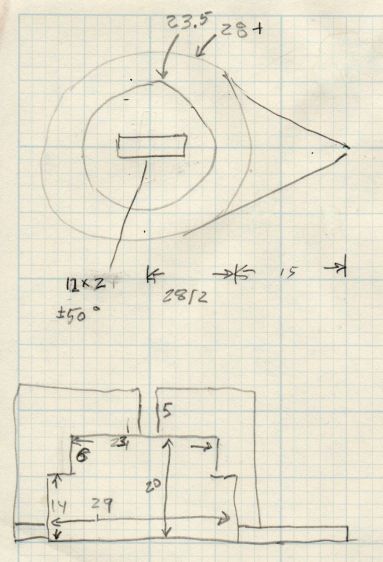
The doodle with useful measurements amid some ideas that did not work out:
This file contains hidden or bidirectional Unicode text that may be interpreted or compiled differently than what appears below. To review, open the file in an editor that reveals hidden Unicode characters.
Learn more about bidirectional Unicode characters
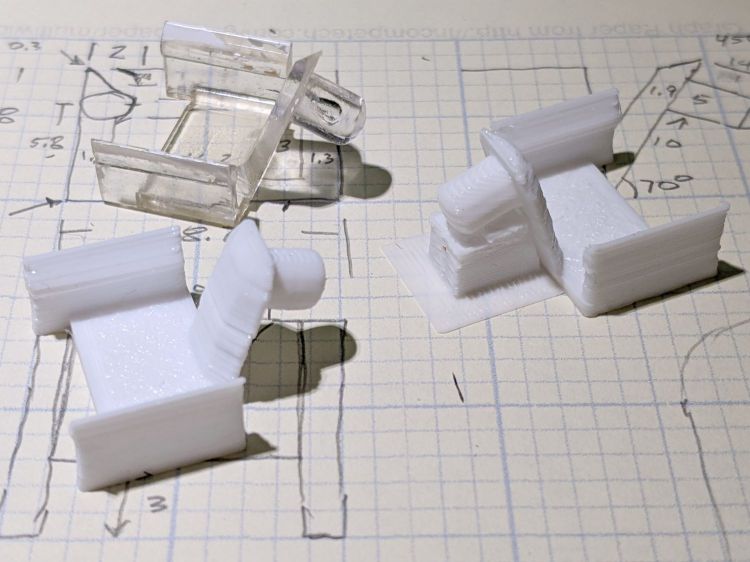
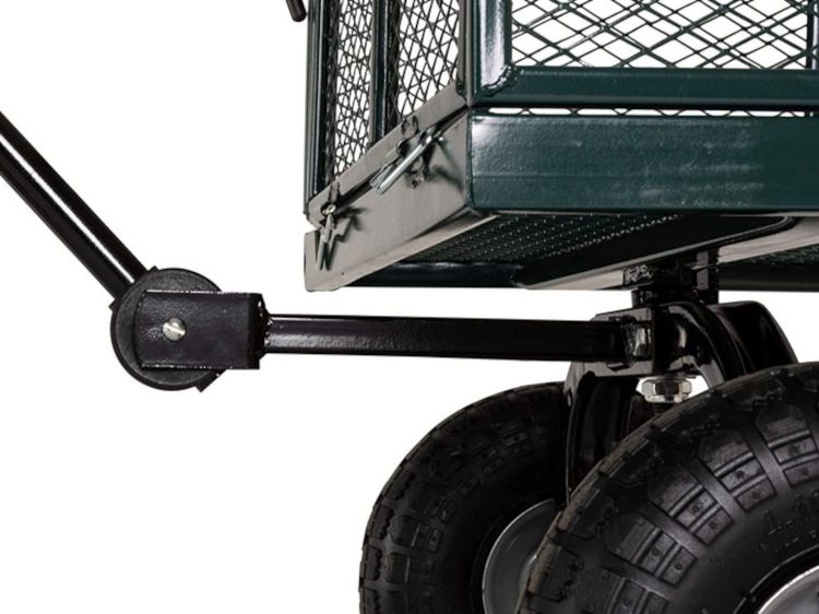
For reasons not relevant here, I was tapped to replace the plastic parts attaching the handle to a garden cart:
Garden Cart – handle attachment
The owner tried to contact the “manufacturer” to no avail; repair parts are simply not available, even if the name painted on the cart had a meaningful relationship to anything else.
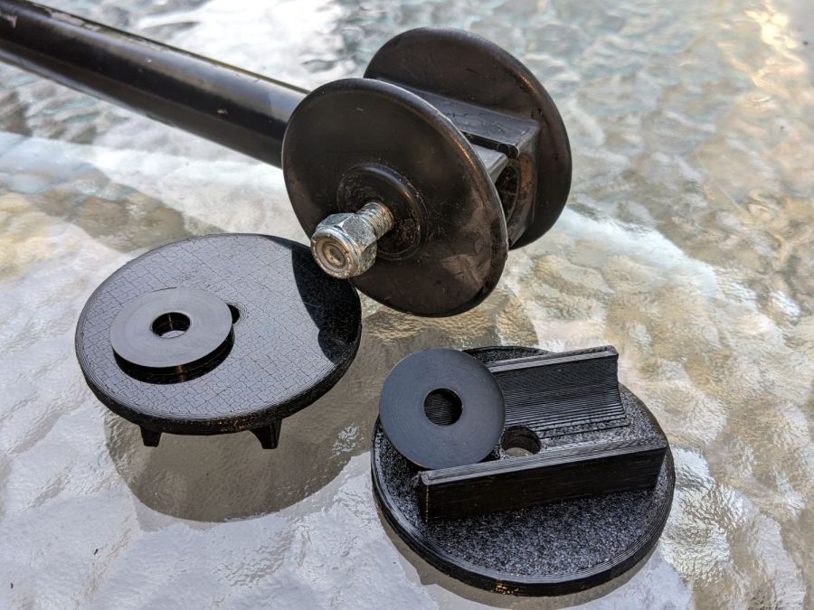
Well, I can fix that:
Garden Cart – handle repair parts
Fortunately, another cart in the fleet provided the missing bits so I could reverse-engineer their measurements.
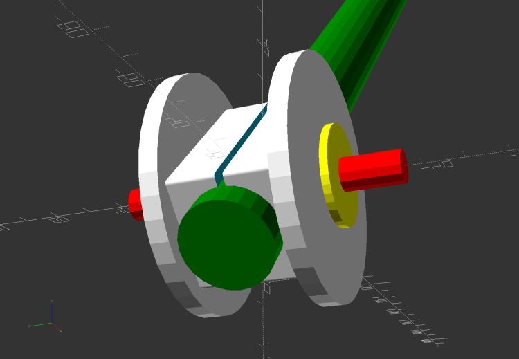
The solid model looks about like you’d expect:
Garden Cart Handle – show view
Printing the two halves with those nice (yellow) bosses in place wasn’t feasible. They were exactly 1 inch in diameter, so I just parted two cookies from the end of a stout acetal rod after drilling a hole for the 2-¼ inch 5/16-18 bolt.
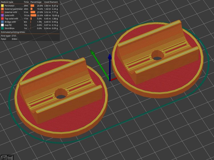
The two pieces took nigh onto three hours with five perimeters and 50% infill:
Garden Cart Handle – slicer preview
While delivering and installing the parts, I got volunteered to haul plants to cars with one of the carts during the upcoming Spring Plant Sale. That’ll teach me to stay in the Basement Shop …
This file contains hidden or bidirectional Unicode text that may be interpreted or compiled differently than what appears below. To review, open the file in an editor that reveals hidden Unicode characters.
Learn more about bidirectional Unicode characters
I cut new shades from vintage clear acrylic sheet, with more aluminized mylar attached to the lower surface: you can barely see the COB LED strip through the reflecting surface.
Depending on how you arrange all the hardware hanging on the nozzle, the shades can collide with something at the home position in the far right corner:
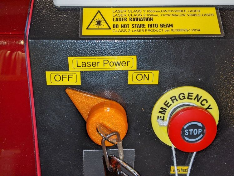
Although the OMTech laser controls the laser power supply with a key-lock switch, there’s little visible difference between the OFF and ON positions. Having occasionally mistaken it in both directions, this seemed like a useful addition:
Laser Power Lock Indicator – installed
The strip of black duct tape below the lock muffles the rattle of the triangle hatch key against the metal cabinet.
Two snippets of foam tape hold the knob to the lock cylinder, making an admittedly tenuous connection, but the knob fits around the outside of the switch housing with minimal clearance and doesn’t shouldn’t suffer any torque or pulling, so it might work.
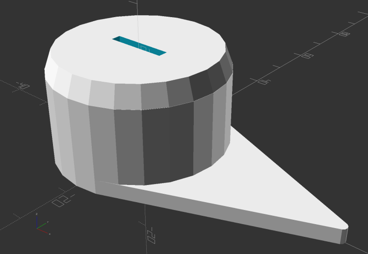
The solid model looks about like you’d expect:
Laser Power Lock Indicator – solid model
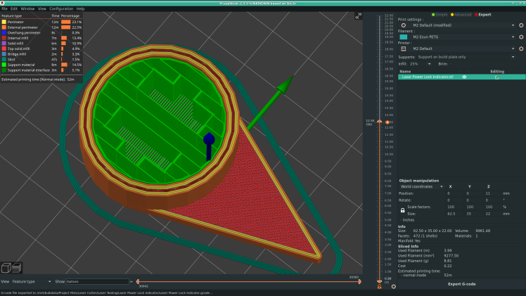
Unfortunately, it has no good orientation for printing, so I let PrusaSlicer generate support material inside the knob:
Laser Power Lock Indicator – Support structures
Suffice it to say: removing all that plastic did not go well.
I eventually grabbed the knob in the lathe and bored the interior out to its more-or-less proper dimensions, figuring nobody would ever notice the carnage, and it worked reasonably well. In the unlikely event I need another pointer, I’ll add a support spider to hold up the interior with minimal contact and less plastic.
Yeah, the laser really needs a stack light showing its condition and safety status …
This file contains hidden or bidirectional Unicode text that may be interpreted or compiled differently than what appears below. To review, open the file in an editor that reveals hidden Unicode characters.
Learn more about bidirectional Unicode characters