The Smell of Molten Projects in the Morning

Ed Nisley's Blog: Shop notes, electronics, firmware, machinery, 3D printing, laser cuttery, and curiosities. Contents: 100% human thinking, 0% AI slop.

Tag: M2

Using and tweaking a Makergear M2 3D printer

  • M2 vs. Marlin: Acceleration

    Three firmware constants (seem to) control the acceleration applied to each axis, presented here in their original form:

    #define DEFAULT_MAX_ACCELERATION      {9000,9000,30,10000}    // X, Y, Z, E maximum start speed for accelerated moves. E default values are good for skeinforge 40+, for older versions raise them a lot.
    #define DEFAULT_ACCELERATION          3000    // X, Y, Z and E max acceleration in mm/s^2 for printing moves
    #define DEFAULT_RETRACT_ACCELERATION  3000   // X, Y, Z and E max acceleration in mm/s^2 for r retracts
    

    I do not pretend to understand their interaction and, pursuant to that discussion, some tests and measurements seem to be the only way to find out what’s happening. However, estimating some masses and guesstimating motor performance can put some boundaries on the problem.

    Based on weighing a slightly larger stepper motor and the hot end, the complete extruder assembly may weigh (OK, mass) about 600 grams, which I’ll round up to 1 kg to cover bending the filament guide tube and friction. In order to accelerate the extruder carriage at 9000 mm/s^2, the X axis stepper motor force must be:

    F = ma = 1 kg * 9 m/s2 = 9 N

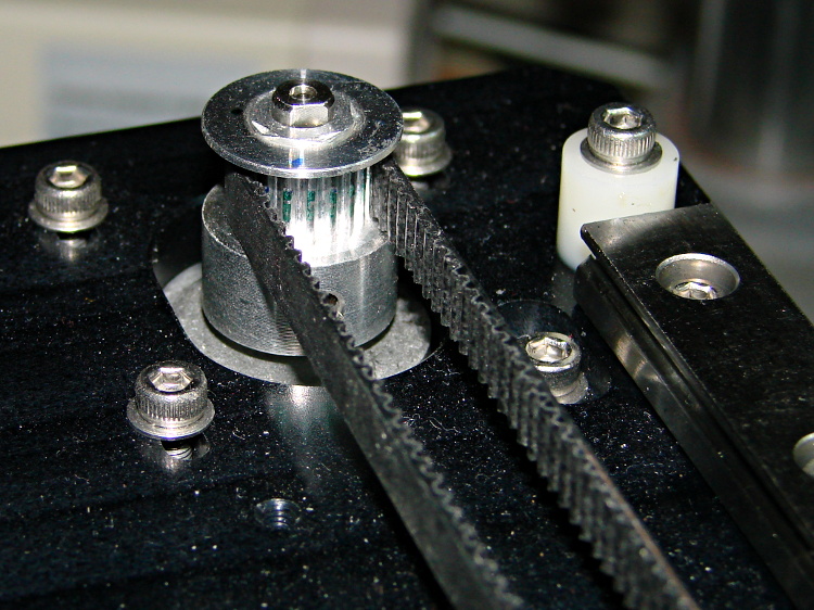
    The pulley drives 36 mm of belt per revolution, so the effective diameter = 11.5 mm and the radius = 5.7 mm. That means the motor torque will be:

    50 mN·m = 9 N * 5.7 mm

    I don’t have specs for the Makergear motors, but similar motors have pull-in torques in the 200 to 300 mN·m range, which is flat out to 1000 (full)step/s and decreases to zilch as the speed approaches 10000 (full)step/s. Because the motors run in 1/16 microstep mode, Marlin’s peak 40000 (micro)step/s rate works out to 2500 (full)step/s, where the motor pull-in torque is maybe half of the maximum.

    The motor pull-out torque falls off to nothing around 1000 (full)step/s = 16000 (micro)step/s, which suggests you can’t slow the stages down nearly as fast as you speed them up, at least beyond about 10000 (micro)step/s.

    All of that depends on the motor current, of course, and that depends on the amount of heat you’re willing to generate in the motors. I really must build a better dynamometer.

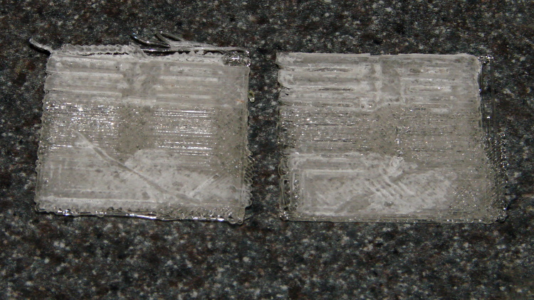
    Assuming the Y stage + heater + glass weighs 4 pounds = 2 kg, the numbers are twice as large, but they’re in the same ballpark.

    I tried a few values for the Z acceleration and settled on something slightly larger, but that won’t apply to a different motor.

    I have no way to estimate the force required to drive the filament, but the gearbox multiplies the motor torque by a factor of 5, so there’s a speed-torque tradeoff lying in wait.

    I modified the acceleration constants to bring the overall limits in line with the per-axis values:

    #define DEFAULT_MAX_ACCELERATION      {9000,9000,75,10000}
    #define DEFAULT_ACCELERATION          10000		// X, Y, Z and E max acceleration in mm/s^2 for printing moves
    #define DEFAULT_RETRACT_ACCELERATION  10000		// X, Y, Z and E max acceleration in mm/s^2 for r retracts
    

    Changing the last two values from 3000 to 10000 produced a dramatic increase in acceleration, so those numbers do act as overall limits on the per-axis values in the first line.

    Because the motion planner ramps the velocity up at the maximum possible acceleration (reduced, as needed, to accommodate the motor with the lowest acceleration involved in the motion), higher acceleration values allow the motor to reach the desired speed sooner, so shorter motions run faster.

    For example, reaching 200 mm/s2 from a standing start requires 6.7 mm at 3000 mm/s2 and 2.2 mm at 9000 mm/s2. Braking to a stop requires the same distance, assuming the pull-out torque allows it. Contemporary motion planners that can match velocities around corners where straight-line segments join will allow higher sustained speeds, so they don’t require slowing to a dead stop.

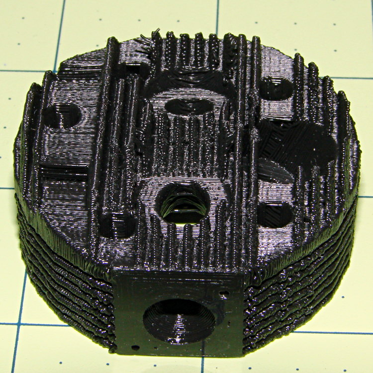
    But, of course, the 3D printer’s overall structure must be rigid enough to restrain the reaction forces caused by high accelerations and the printer must be anchored well enough to not sidle off the table. The M2 can handle a single high-speed move, but chaining multiple moves together shakes the steel chassis rather violently; that happens when you select the Slic3r “Avoid crossing perimeters” option.

  • M2 vs. Marlin: Speed Calculations

    Knowing the number of motor steps required to move an axis by 1 mm, the next step is to figure out how fast each axis can possibly move, given the restrictions of the Marlin firmware driving the motors.

    Dan Newman pointed out that Marlin runs with a maximum 10 kHz interrupt rate, with up to four steps issued per interrupt. The constant controlling (or at least defining) that is in Configuration_adv.h (with a comment that seems irrelevant to the M2’s setup):

    #define MAX_STEP_FREQUENCY 40000       // Max step frequency for Ultimaker (5000 pps / half step)
    

    Below the 10 kHz rate, the step interrupt occurs whenever the next step must happen, so it does not have a constant frequency. Above 10 kHz, the steps (seem to) emerge in bursts, so there’s likely a good bit of jitter that I should measure. In any event, there’s an obvious loss of resolution at high speeds, which is a problem common to all variable-frequency pulse generators that’s worse for relatively low-frequency software generators used in high-speed applications.

    In any event, these numbers show the absolute maximum possible speed for each axis:

    • X and Y axes: 450 mm/s = (40 k step/s) / (88.89 step/mm)
    • Z axis: 100 mm/s = (40 k step/s) / (400 step/mm)
    • Extruder: 94.3 mm/s = (40 k step/s) / (424.4 step/mm)

    Due to the low torque available from the Z axis motor, the actual maximum speed seems to be around 30 mm/s = 1800 mm/min. After I replace the motor, I’ll measure the actual performance and see what’s reasonable.

    One could quibble about the extruder, as the extrusion multiplier affects the final speed. The extruded thread squirts out at a pretty good clip if the motor turns at full speed:

    2350 mm/s = (1.75 mm)2 / (0.35 mm)2 * 94 mm/s

    It’s not clear the hot end can melt plastic fast enough to keep up with that pace more than momentarily, but I haven’t measured that yet.

    However, if the X and Y axes both move at 450 mm/s, then the nozzle moves at 640 mm/s = √2 * 450 mm/s relative to the platform, so the maximum extruder speed while printing will be roughly:

    26 mm/s = (640 mm/s) * (0.35 mm)2 / (1.75 mm)2

    That assumes the printed thread has the same cross-section area as the nozzle, which is roughly true for my choice of output:

    • Thread: 0.1 mm2 = 0.4 mm wide * 0.25 mm thick
    • Nozzle: 0.096 mm2 = pi * (0.35 mm)2 / 4

    If you bake the extrusion multiplier into the step/mm value, then compute the maximum speed without applying the same multiplier in slic3r, the plastic should come out of the nozzle at the same speed.

    So the speed setup looks like this:

    #define DEFAULT_MAX_FEEDRATE          {450, 450, 30, 94}    // (mm/sec)
    
  • M2 vs. Marlin: Step/mm Calculations

    After Dan Newman nudged me a bit in the comments to the Z axis calculations, I walked through the constants in Marlin’s Configuration.h file to see if they were all consistent. The earlier values sufficed to get going, but a bit of pondering suggested some tweaks.

    The motor microstepping mode determines the number of (micro)steps per motor (single)step:

    #define MICROSTEP16
    

    That single constant implies all motors must run in the same microstepping mode. Typical stepper motors have 200 full step/rev = 1.8°/step, so 1/16 microstepping means 3200 step/rev.

    However, each motor can have a different “gear” ratio that converts from motor rotation to linear distance, so you must measure or calculate the actual values.

    For the X and Y axes, the motor pulleys have 18 teeth and the belt pitch is 2 mm/tooth, so one motor revolution drives the belt:

    36 mm = 18 teeth * 2 mm/tooth
    M2 - X axis motor pulley
    M2 – X axis motor pulley

    Each revolution requires 3200 steps, so the X and Y stages move at:

    88.888 step/mm = 3200 step / 36 mm

    Makergear uses 88.88 step/mm, rather than the rounded 88.89, but the difference across 250 mm amounts to 2.5 steps, so it doesn’t matter.

    For the Z axis, the four-start leadscrew moves the stage 8 mm, so:

    400 step/mm = 3200 step / 8 mm
    M2 Z axis bearing - shimstock bushing
    M2 Z axis bearing – shimstock bushing

    The situation with the extruder drive isn’t quite so clear, because the actual filament movement depends on the effective diameter of the drive pulley’s teeth engaging the filament. Mechanically, the extruder motor runs a 5:1 gearbox, so each drive pulley rotation requires 16000 (micro)steps.

    The filament drive pulley has 22 teeth and a 12.0 mm OD = 37.7 mm circumference:

    424.4 step/mm = 16000 step / 37.7 mm
    M2 - Filament Drive Gear
    M2 – Filament Drive Gear

    That’s measured at the tooth tip. If you think of the filament as being a belt, then you’d expect it to move precisely that distance… except that the teeth dig into the filament, so the effective diameter comes out a bit smaller and the step/mm value a bit higher.

    Makergear’s default 471.5 step/mm is, indeed, larger, but the ratio of the two values seems both oddly familiar and eerily exact:

    0.900 = 424.4 / 471.5

    The “packing density” Fudge Factor (yclept extrusion multiplier by slic3r) that accounts for the difference between the drive gear OD and the actual filament motion runs around 0.9, with passionate arguments justifying more specific values. It looks like Makergear baked that number into the firmware, so the nominal slic3r extrusion multiplier should be pretty close to 1.0.

    After a few quick measurements while getting the printer running, I settled on extrusion multiplier = 0.9, so the actual step/mm value in effect for the extruder works out to:

    424.4 = (471.5 step/mm) * 0.9

    Now, that would seem to imply that the filament skates along the top of teeth, but that’s not the case:

    M2 extruder - filament embossing
    M2 extruder – filament embossing

    So, for whatever reason, the effective diameter of the drive pulley matches its actual OD. That will surely vary with a number of imponderables, including the setting for the clamp screw holding the bearing against the filament and drive pulley.

    Being that type of guy, I favor baking the actual drive pulley OD into the firmware (because I can actually measure that value), then using the extrusion multiplier to account for the difference. I’ve heard cogent arguments to the contrary, but, for my purposes, the proper value for the extruder should 424.4 step/mm, with a corresponding extrusion multiplier change to 1.00 in slic3r’s configuration.

    I wouldn’t be surprised in the least to discover:

    • I’m multiplying where I should be dividing (or the other way around)
    • There’s a squaring / rooting operation hidden somewhere in there (area vs length)
    • Another obvious blunder has tripped me up

    Selah.

  • PLA vs. PVC Purple Primer: Win!

    After that exchange, I dabbed some Oatey PVC Purple Primer/Cleaner on two PLA slabs:

    PLA test coupon - PVC Purple Primer
    PLA test coupon – PVC Purple Primer

    The active ingredient involved in PLA bonding is tetrahydrofuran, which makes up anywhere from 10 to 40% of the primer (the MSDS gives a broad range). The primer immediately marred the PLA surface, which is exactly what you want in a solvent adhesive.

    After an overnight clamping, I couldn’t pull or peel that joint apart: the two slabs had become one. That’s unlike the paint stripper test that didn’t bond well at all. Good enough for me.

    Obviously, you’d prefer Clear Primer for natural PLA, but Purple Primer is what I had on hand.

    Given that this stuff has no solid content, I think it’s more suitable as a PLA adhesive that the thicker PVC Cement. However, clear cement would be less likely to run along the thread seams and ruin the surface finish outside the joint than water-thin primer.

    Tradeoffs, tradeoffs… but now I can build things from PLA subassemblies!

  • PLA vs. Methylene Chloride: Joint Peel Strength

    The only commonly available PLA adhesive seems to be methylene chloride, which is common only because it’s part of really nasty paint stripper that actually works; I suspect you can’t buy the pure stuff anywhere.

    Anyhow, I picked a pair of flat line width test plates from the PLA scrap pile, dabbed paint stripper on each, and clamped them together overnight:

    PLA test coupon - clamping
    PLA test coupon – clamping

    Unlike acetone on ABS, paint stripper doesn’t actually combine the parts into a single fused unit; I could peel the two plates apart with some effort:

    PLA test coupon - paint stripper adhesion
    PLA test coupon – paint stripper adhesion

    That picture shows the results of two glue-and-peel tests, with much the same result along the top and bottom edges. Some solvent damage appears as a thin white line around the edge of the glued joint, but with some care that wouldn’t be too bad.

    I think paint stripper makes an acceptable adhesive for PLA, at least for joints that aren’t subject to peeling loads. You must design an interlocking mechanical joint, perhaps filled with epoxy, to withstand peeling loads, which isn’t nearly as good as the ABS option of just fusing the parts together.

  • Makergear M2: Radial Engine Cylinder Head

    After some chiding by Jetguy, here’s a cylinder head from the MBI radial engine:

    Radial engine cylinder head - top - plug oblique
    Radial engine cylinder head – top – plug oblique

    The side fins came out nicely, but the top fins had a few misplaced threads (far side to the left of the valve):

    Radial engine cylinder head - intake
    Radial engine cylinder head – intake

    The view from the other port:

    Radial engine cylinder head - exhaust
    Radial engine cylinder head – exhaust

    Seen directly from the spark plug side, you can barely make out the impossibly thin fin section arching over the plug hole:

    Radial engine cylinder head - plug side
    Radial engine cylinder head – plug side

    The cylinder side looks OK:

    Radial engine cylinder head - bottom
    Radial engine cylinder head – bottom

    I built it standing on one of the ports with the fins vertical, as shown above, which is probably the only way to do it without soluble support material. If I were doing it for real with non-soluble support, I’d be tempted build it flat on the cylinder side with support under the piston head and thin support blocks inside the side fins. It’d look about the same, but with better finish on the top fins.

    All in all, I’d say it looks pretty good.

    The Slic3r header:

    ; generated by Slic3r 0.9.10-dev on 2013-04-20 at 20:24:18
    
    ; layer_height = 0.20
    ; perimeters = 1
    ; top_solid_layers = 3
    ; bottom_solid_layers = 3
    ; fill_density = 0.1
    ; perimeter_speed = 60
    ; infill_speed = 80
    ; travel_speed = 200
    ; nozzle_diameter = 0.35
    ; filament_diameter = 1.73
    ; extrusion_multiplier = 0.9
    ; perimeters extrusion width = 0.52mm
    ; infill extrusion width = 0.52mm
    ; solid infill extrusion width = 0.52mm
    ; top infill extrusion width = 0.52mm
    

    The STL file came direct from Thingiverse, riddled with the reversed normals and holes common to solid models generated by Sketchup, but a pass through NetFabb’s cleanup made it printable. The original STL positioned it far, far out on the X axis, so if you don’t see it right away, rummage around a bit.

  • Printed Chain Mail: Subtractive Model

    This is a subtractive version of Zomboe’s Chainmail, built by removing chunks from a solid rectangle the size of one link:

    Chain Mail Link - Subtractive
    Chain Mail Link – Subtractive

    Until what’s left is, indeed, a single link:

    Chain Mail Link
    Chain Mail Link

    The pillars in the original model weren’t nearly large enough; Slic3r omitted them from the G-Code. They’re now as wide as the bars and √2 times that width long, which means they actually get a bit of fill.

    Then a pair of nested loops replicates that link across the entire fabric:

    Chain Mail Sheet
    Chain Mail Sheet

    That technique didn’t work with Skeinforge (because it sent the nozzle scampering all over each layer, knocking things loose) and it didn’t work with Slic3r 0.9.8 (because it had problems with bridges), but Slic3r 0.9.10, hot from github, produced good results:

    Chain Mail - as built
    Chain Mail – as built

    There were some strings connecting adjacent links, but a few minutes with a flush cutter solved that. Retraction was 1 mm at 80 mm/s = 480 mm/min, which seems to work fine in other contexts, but adjacent links fell inside the 1 mm minimum distance setting I’d been using. That’s now down to 0.5 mm, which should suffice for nearly everything.

    The M2 sounded like I was hitting it with a hammer: each of the 480 pillar layers (!) required a quick squirt and a retraction, followed by a 500 mm/s move. Worked fine and didn’t miss a step anywhere along the way.

    A view from the bottom shows it really is flexy:

    Chain Mail - bottom
    Chain Mail – bottom

    I used zero perimeter threads on these tiny links, which means you can see the ripply edges of the second layer that was crosswise to the length of the link bars. Next time, I’ll try one perimeter thread, which should smooth that out.

    The links stuck to the glass like they were glued, which, indeed, they were: White Rain Unscented Extra Hold Hairspray in a pump bottle (either they didn’t have Maximum Hold pump spray or I couldn’t see it). I’m not a big fan of aerosol anything and decided to try wiping the stuff across the platform glass, rather than filling the air with a fine mist and getting some on the glass. Seems to work, but more examples are needed…

    The Slic3r configuration:

    ; generated by Slic3r 0.9.10-dev on 2013-04-17 at 17:28:11
    ; layer_height = 0.25
    ; perimeters = 0
    ; top_solid_layers = 3
    ; bottom_solid_layers = 3
    ; fill_density = 0.10
    ; perimeter_speed = 100
    ; infill_speed = 100
    ; travel_speed = 500
    ; nozzle_diameter = 0.35
    ; filament_diameter = 1.73
    ; extrusion_multiplier = 0.9
    ; perimeters extrusion width = 0.40mm
    ; infill extrusion width = 0.40mm
    ; solid infill extrusion width = 0.40mm
    ; top infill extrusion width = 0.40mm
    

    The OpenSCAD source code, with the platform marker cubes expanded to cover the M2’s glass plate:

    // Chain Mail Sheet
    // For Slic3r and M2 printer
    // Ed Nisley KE4ZNU - Apr 2013
    
    Layout = "Build";			// Link Build
    
    //-------
    //- Extrusion parameters must match reality!
    //  Print with +0 shells and 3 solid layers
    
    ThreadThick = 0.25;
    ThreadWidth = 0.40;
    
    HoleWindage = 0.2;
    
    Protrusion = 0.1;			// make holes end cleanly
    
    function IntegerMultiple(Size,Unit) = Unit * ceil(Size / Unit);
    
    //-------
    // Dimensions
    
    BarWidth = 5 * ThreadWidth;
    BarThick = 3 * ThreadThick;
    
    LinkSquare = IntegerMultiple(13.0,ThreadWidth);
    LinkHeight = 2*BarThick + 1*BarThick;
    
    LinkOutDiagonal = LinkSquare*sqrt(2) - BarWidth;
    LinkInDiagonal = LinkSquare*sqrt(2) - 2*(BarWidth/2 + BarWidth*sqrt(2));
    
    echo("Outside diagonal: ",LinkOutDiagonal);
    
    SheetSizeX = 75;
    SheetSizeY = 100;
    
    NumLinksX = 1 + floor(SheetSizeX / LinkOutDiagonal);
    NumLinksY = 1 + floor(SheetSizeY / LinkOutDiagonal);
    
    echo("Links X: ",NumLinksX," Y: ",NumLinksY);
    
    LinkSpacing = 0.59 * LinkOutDiagonal;
    
    //-------
    
    module ShowPegGrid(Space = 10.0,Size = 1.0) {
    
      RangeX = floor(95 / Space);
      RangeY = floor(125 / Space);
    
    	for (x=[-RangeX:RangeX])
    	  for (y=[-RangeY:RangeY])
    		translate([x*Space,y*Space,Size/2])
    		  %cube(Size,center=true);
    
    }
    
    //-------
    // Create basic link
    
    module Link() {
    
    	rotate(45)
    		difference(convexity=2) {
    			translate([0,0,LinkHeight/2]) {
    				difference(convexity=2) {
    					intersection() {		// outside shape
    						cube([LinkSquare,LinkSquare,LinkHeight],center=true);
    						rotate(45)
    							cube([LinkOutDiagonal,LinkOutDiagonal,LinkHeight],center=true);
    					}
    					intersection() {		// inside shape
    						cube([(LinkSquare - 2*BarWidth),(LinkSquare - 2*BarWidth),(LinkHeight + 2*Protrusion)],center=true);
    						rotate(45)
    							cube([LinkInDiagonal,LinkInDiagonal,(LinkHeight +2*Protrusion)],center=true);
    					}
    				}
    			}
    			for (i=[-1,1]) {				// create bars
    				translate([0,-i*(sqrt(2)*BarWidth/2),BarThick])
    					rotate(45 + 180*(i+1)/2)
    						cube([LinkOutDiagonal,LinkOutDiagonal,LinkHeight]);
    				translate([i*(sqrt(2)*BarWidth/2),0,-BarThick])
    					rotate(135 + 180*(i+1)/2)
    						cube([LinkOutDiagonal,LinkOutDiagonal,LinkHeight]);
    			}
    		}
    }
    
    //-------
    // Build it!
    
    ShowPegGrid();
    
    if (Layout == "Link") {
      Link();
    }
    
    if (Layout == "Build") {
    	for (ix=[-(NumLinksX/2 - 0):(NumLinksX/2 - 1)])
    		for (iy=[-(NumLinksY/2 - 0):(NumLinksY/2 - 1)])
    			translate([ix*LinkSpacing + LinkSpacing/2,iy*LinkSpacing + LinkSpacing/2,0])
    				Link();
    }

    [Update: The original doodles, in case I ever need the background info:]

    Chain Mail - Link Dimension Doodles
    Chain Mail – Link Dimension Doodles