I planned to use an old Dell Inspiron 531S AMD desktop for the LinuxCNC installation, but it turned out to have terrible interrupt latency, despite fiddling with all the available BIOS settings and video drivers. Mostly, it ran fine, but would occasionally burp up a millisecond-long latency spike for no apparent reason. So it’s now on the harvest / recycle heap.
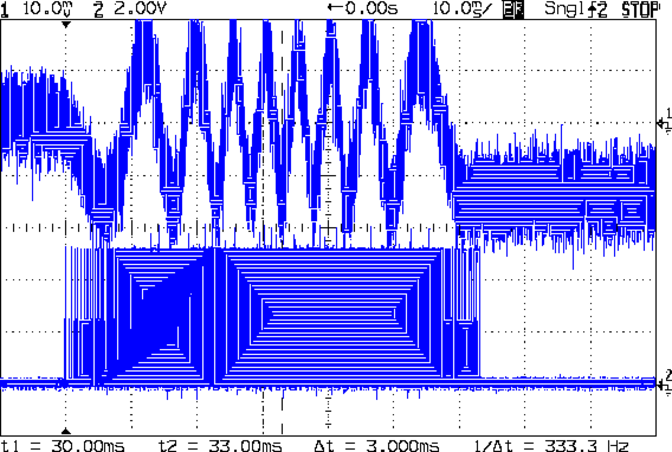
A new-to-me off-lease Dell Optiplex 760 Core 2 Duo in the SDT (Small Desktop Tower) configuration has similar latency numbers:

What’s important here is that the latency remains rock-solid stable at those numbers. Contrary to my experience with the D520 and D525 Atoms, isolating one CPU for the real-time tasks didn’t make any noticeable difference, but it’s running that way because the overall performance isn’t a problem.
Latency around 20 μs is near the upper limit for successful software step generation at any reasonable pace; the LinuxCNC description has more details. In round numbers, running the M2 at 500 mm/s needs a 40 kHz step rate in 1/16 microstep mode = a 25 μs period, which means 20 μs of jitter wouldn’t work well at all. Which is why I’m using Mesa FPGA card to get hardware step generation: it makes such problems Go Away.
The Optiplex arrived with Windows Vista Business preinstalled; it dates back to mid-2009. I used System Rescue CD to shrink the Windows partition, added a few more, then installed LinuxCNC direct from the CD image (based on Ubuntu 10.04 LTS) and Xubuntu 13.04. The latter serves as a general-purpose installation for times when I don’t need LinuxCNC, because 10.04 is pretty much obsolete for anything other than real-time control.
Digression 1: Yes, 10.04 LTS. TheRTAI project hasn’t released the patches that will slip the real-time kernel under the stock 3.x Linux kernel: LinuxCNC remains stuck at 10.04 LTS. Those changes have been coming Real Soon Now for quite a while; as with most Open Source projects, they could use more manpower and money. This isn’t a problem, as LinuxCNC is used for motion control, not a general-purpose operating system.
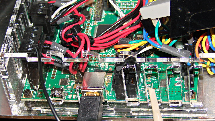
The SDT case has room for two PCI cards and one PCI-E video card, so I installed the dual-head video card that couldn’t handle the U2711 monitor’s dual-DVI connection (although I’m using only DVI Output 1) and a Mesa 5i25. The middle “card” is actually a tiny PCB connected to a ribbon cable that brings out a second serial port (remember serial ports?) and what could be either or both of a PS2 keyboard or mouse connection (remember PS/2?).

The back panel has a parallel printer port (which may come in handy for something) and a serial port, although you’re expected to have USB mice and keyboards these days. The front panel even has a floppy drive…
Digression 2: LinuxCNC does not require a parallel printer port; this seems to be a common misconception among folks who don’t actually know how it works. The Mesa 5i25 FPGA card with a 7i76 step-direction daughter board provides high-resolution timing for five axes, rotary encoder inputs, a bunch of buffered digital I/O bits, a watchdog timer, plus various other useful odds and ends, all behind handy screw terminals.
The Optiplex 760 has on-board VGA-class video that would also work fine, but the monitor I’m using has its VGA input connected to the box driving the Sherline mill and an unused DVI input. Having that dual-DVI monitor card lying around, I figured I could attach the same monitor to both systems and just poke the monitor’s input section button; I’ve found KVM switches unreliable in this application.
The usual setup preps the system for public-key SSH on a nonstandard port, sets up the NFS mounts, and tweaks this-and-that: it’s running just fine.
Digression 3: SSH kvetches when you swap server boxes at the same IP address, as well it should. If you’re foolish enough to have two separate Linux installs on the same box with the same IP, SSH reminds you every time you boot the other distro…