Ed Nisley's Blog: Shop notes, electronics, firmware, machinery, 3D printing, laser cuttery, and curiosities. Contents: 100% human thinking, 0% AI slop.
I applied a tiny rat-tail file to the holes until they became a free sliding fit for the screws.
The wave springs are mostly decoration, as the silicone rubber disks now take the compression load from the screws, and the platform is quite rigidly mounted.
The new platform eliminates the M2’s original aluminum support spider, the aluminum heater & heat spreader, and the corner supports & clips, all of which add up to about 780 g. I didn’t bother changing the Y axis acceleration to match, as all those numbers seem rubbery.
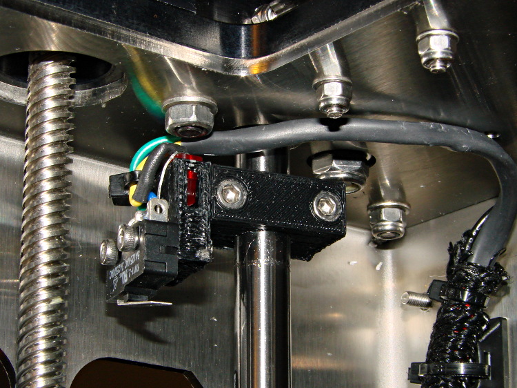
Minus the support spider, the platform rides much lower on the Z axis stage than the M2’s platform. Unfortunately, the Z-min switch clamped to the top of the rear Z-axis guide rod can’t get any higher, even after rearranging the cable and fiddling with the LED:
M2 – Z min limit switch
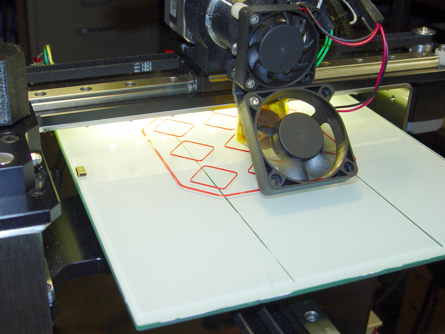
As a first-pass hack, I moved the switch to the rear of the X gantry and applied Gorilla Tape to hold it in place:
M2 – Z-min switch at rear X gantry
That required a small block to raise the platform enough to activate the switch before hitting the nozzle. I epoxied a snippet of brass rectangle tube to the left edge of the platform, directly under the switch lever:
M2 – Improved HBP – rear switch tab
The awkward position activates the switch with the platform as far to the rear as possible, so that you can’t inadvertently drag the dangling switch lever across the block in the wrong direction.
I think it’s stupid, too, but it let me bring up the printer and make sure all the electronics kept working. The next step was to relocate the switch to a more rational place
The improved platform for the M2 runs at 30 V, but the RAMBo board specs limit the max HBP voltage to 24 V, presumably because the 15 A ATO fuse won’t clear a high-voltage, high amperage DC short. While setting up the SSR that drives the new platform, I looked up the specs for the PSMN7R0-60YS MOSFET controlling the bed heater and … it doesn’t have a logic level gate.
The rDS spec is an impressive 6.4 mΩ max, but that’s at VGS = 10 V. The 1 mA threshold voltage VGS(th) = 4 V max, which means there’s only 1 V of headroom to turn the transistor on enough to pass upwards of 10 A.
The typical ID vs. VGS curve (Fig 6) shows 20 A at maybe 4.2 V, but the typical RDSon curve (Fig 8) shows the resistance skyrocketing for VGS under maybe 4.8 V; sliding that curve a wee bit to the right would cause a Very Bad Thing to take place.
A 20 mΩ resistance dissipates 4.5 W at 15 A, which seems rather aggressive for the small PCB copper-pour heatsink on the RAMBo board. It’s a somewhat more bearable 2 W at 10 A, but I think that’s still too high. Of course, the typical dissipation will should be much lower…
A good engineering rule of thumb is to ignore the datasheet’s “Typical” column and design using the “Minimum” or “Maximum” columns, as appropriate. When you depend on typical specs, getting “the same part” from a different supplier can provide a real education in supply-chain management.
I suspect tolerance stacking works well enough that nearly all the MOSFETs on nearly all the RAMBo boards run cool enough to survive, but I’d rather see logic-level MOSFETs in Arduino circuits where the maximum gate voltage won’t ever get above 5 V.
If I were doing it, I’d add 1.75 mm alignment holes in each part, but clamping each phalange in both directions came out close enough:
Anthromod Finger – clamping
The tolerances were a bit tight and it required some trimming before all the joints flexed freely. I used short segments of 3 mm orange filament for the knuckle hinges and heat-staked the ends, rather than having to trim a trio of 3 mm screws:
Anthromod Finger – detail
After making three short rubber bands by tying and trimming loops from a longer band, the finger curled up just like yours:
Anthromod Finger – curled
The overall quality isn’t as good as I’d like: there’s a bit of uplift on the edges and corners. If I print another one, I want to try less than 0.2 infill and less cooling.
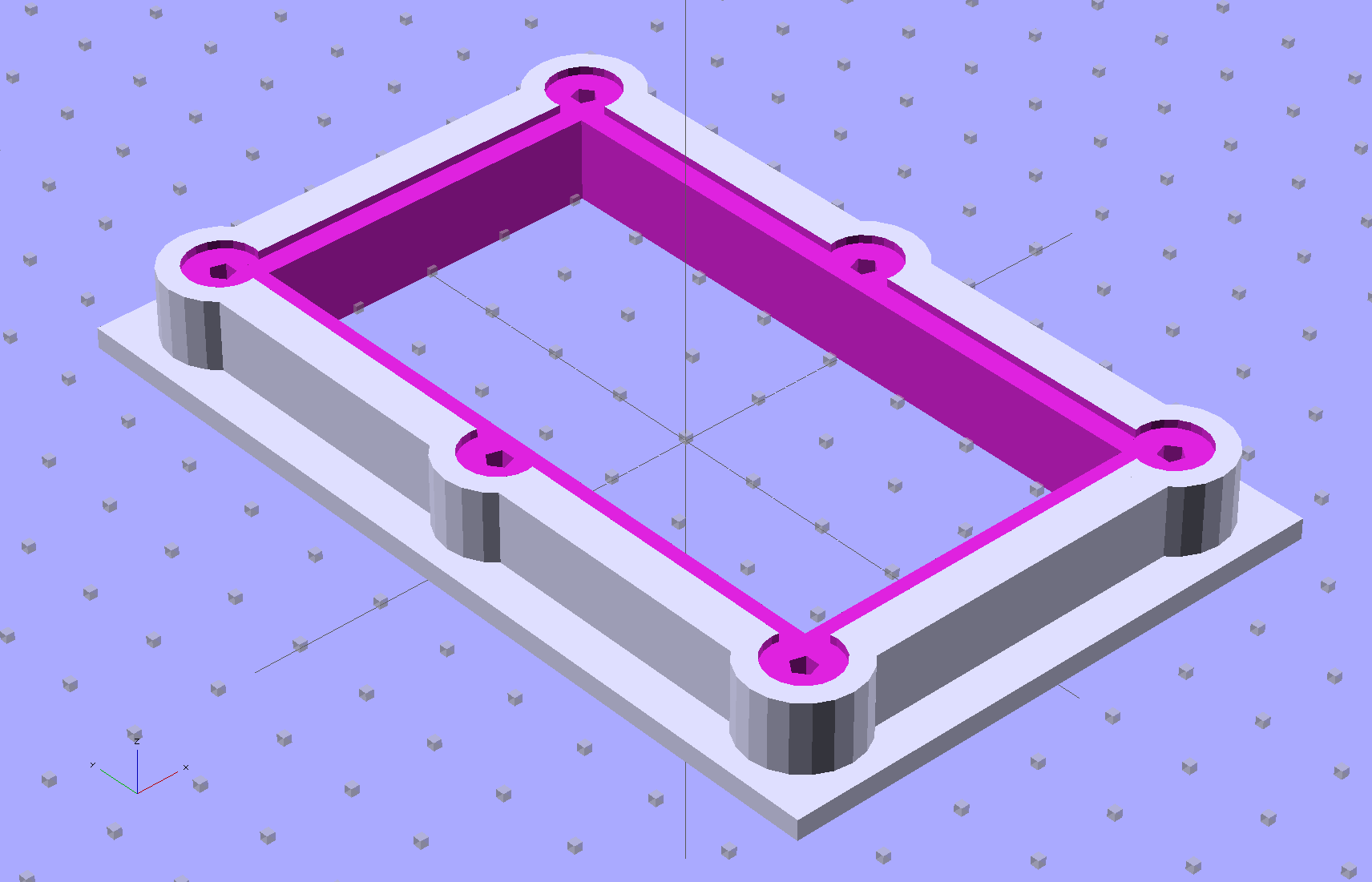
The brassboard PCB for the Hall effect blinky light is too bendy for the SMD parts to survive much debugging, particularly with all the wires hanging off the edges, so I whipped up a stiff mounting bracket that captures the whole thing, with a flange that fits in the work stand arms:
PCB Test Frame – solid model
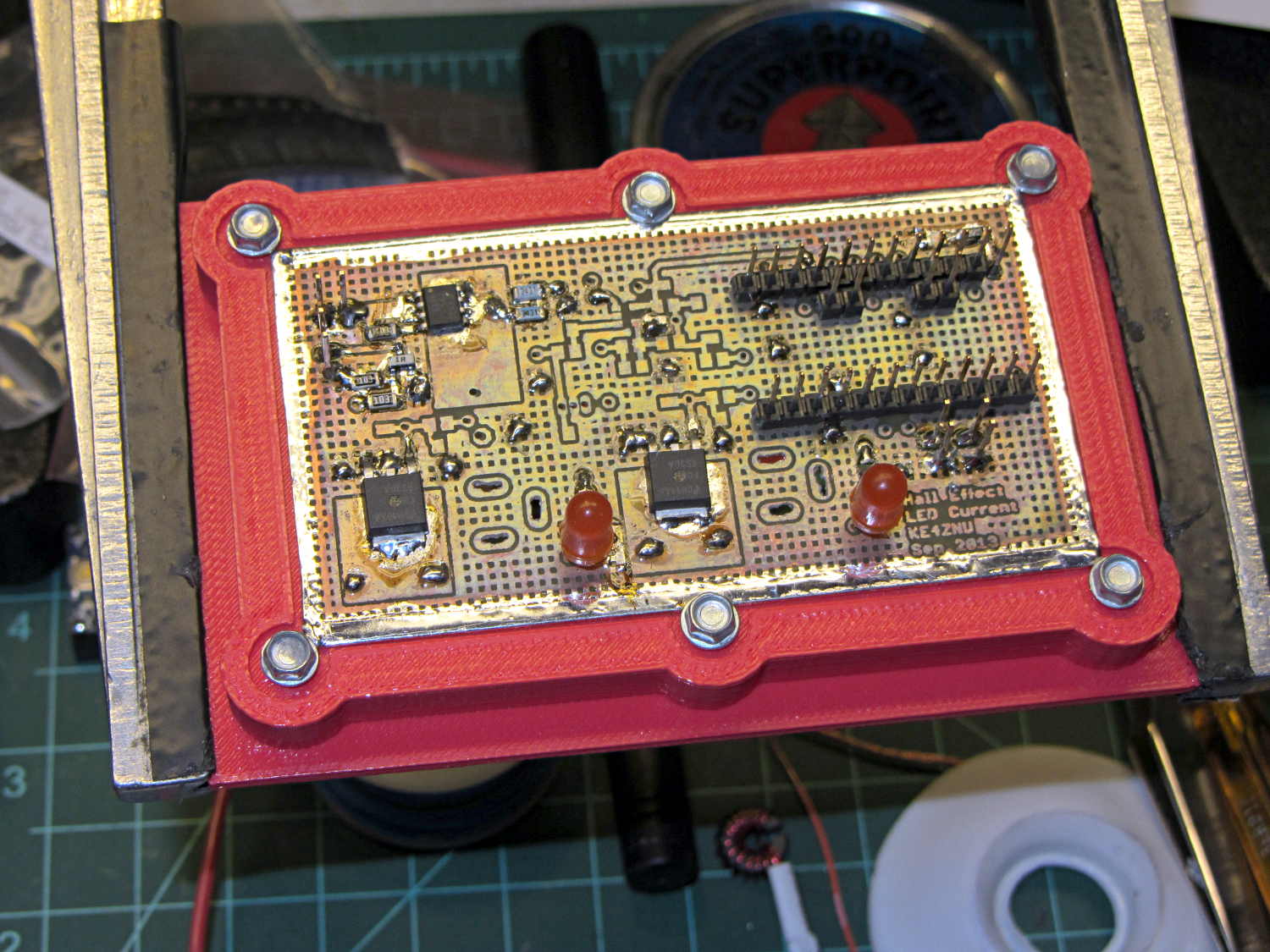
I ran some self-tapping 4-40 hex-head screws into the holes while the plastic was still warm on the M2’s platform:
PCB stiffener with screws on M2 platform
Six screws seem excessive and I’ll probably wind up using just the middle two, but there’s no harm in having more holes and fittings than you really need.
The flange fits neatly into the board holder on the Electronics Workbench, above all the construction clutter:
PCB stiffener in board holder
The nice thing about having a 3D printer: when you need an object like this, a couple of hours later you have one!
The OpenSCAD source code, slightly improved based the results you see above:
// Test support frame for Hall Effect LED Blinky Light
// Ed Nisley KE4ZNU - Sept 2013

ClampFlange = true;

//- Extrusion parameters - must match reality!

ThreadThick = 0.25;
ThreadWidth = 0.40;

function IntegerMultiple(Size,Unit) = Unit * ceil(Size / Unit);

Protrusion = 0.1;

HoleWindage = 0.2;

//- Screw sizes

inch = 25.4;

Tap4_40 = 0.089 * inch;
Clear4_40 = 0.110 * inch;
Head4_40 = 0.211 * inch;
Head4_40Thick = 0.065 * inch;
Nut4_40Dia = 0.228 * inch;
Nut4_40Thick = 0.086 * inch;
Washer4_40OD = 0.270 * inch;
Washer4_40ID = 0.123 * inch;

//- PCB sizes

PCBSize = [46.5,84.0,1.0];
PCBShelf = 2.0;

Clearance = 4*[ThreadWidth,ThreadWidth,0];

WallThick = IntegerMultiple(4.0,ThreadWidth);
FrameHeight = 5.0;

ScrewOffset = 0.0 + Clear4_40/2;

OAHeight = FrameHeight + Clearance[2] + PCBSize[2];

FlangeExtension = 3.0;
FlangeThick = IntegerMultiple(1.5,ThreadThick);
Flange = PCBSize
			+ 2*[ScrewOffset,ScrewOffset,0]
			+ 2*[Washer4_40OD,Washer4_40OD,0]
			+ [2*FlangeExtension,2*FlangeExtension,(FlangeThick - PCBSize[2])]
			;

echo("Flange: ",Flange);
NumSides = 4*5;

//- Adjust hole diameter to make the size come out right

module PolyCyl(Dia,Height,ForceSides=0) {			// based on nophead's polyholes

  Sides = (ForceSides != 0) ? ForceSides : (ceil(Dia) + 2);

  FixDia = Dia / cos(180/Sides);

  cylinder(r=(FixDia + HoleWindage)/2,h=Height,$fn=Sides);
}

//- Put peg grid on build surface

module ShowPegGrid(Space = 10.0,Size = 1.0) {

  RangeX = floor(100 / Space);
  RangeY = floor(125 / Space);

	for (x=[-RangeX:RangeX])
	  for (y=[-RangeY:RangeY])
		translate([x*Space,y*Space,Size/2])
		  %cube(Size,center=true);

}

//- Build it

ShowPegGrid();

difference() {
	union() {									// body block and screw bosses
		translate([0,0,OAHeight/2])
			color("LightBlue")
			cube(PCBSize + Clearance + [2*WallThick,2*WallThick,FrameHeight],center=true);
		for (x=[-1,1], y=[-1,0,1]) {
			translate([x*(PCBSize[0]/2 + ScrewOffset),
						y*(PCBSize[1]/2 + ScrewOffset),
						0])
				color("Orchid") cylinder(r=Washer4_40OD,h=OAHeight,$fn=NumSides);
		}
		if (ClampFlange)
			translate([0,0,Flange[2]/2])
			color("SeaGreen") cube(Flange,center=true);
	}

	for (x=[-1,1], y=[-1,0,1]) {				// screw holes and washer recesses
		translate([x*(PCBSize[0]/2 + ScrewOffset),
					y*(PCBSize[1]/2 + ScrewOffset),
					-Protrusion])
			rotate((x-1)*90)
			PolyCyl(Tap4_40,(OAHeight + 2*Protrusion));
		translate([x*(PCBSize[0]/2 + ScrewOffset),
					y*(PCBSize[1]/2 + ScrewOffset),
					OAHeight - PCBSize[2]])
			PolyCyl(1.2*Washer4_40OD,(PCBSize[2] + Protrusion),NumSides);
	}

	translate([0,0,OAHeight/2])					// through hole below PCB
		cube(PCBSize - 2*[PCBShelf,PCBShelf,0] + [0,0,2*OAHeight],center=true);

	translate([0,0,(OAHeight - (PCBSize[2] + Clearance[2])/2 + Protrusion/2)])	// PCB pocket on top
		cube(PCBSize + Clearance + [0,0,Protrusion],center=true);
}
The 36 V supply has the same M4 mount points as the 24 V supply, so I cut up another pair of those long 6-32 threaded standoffs to make four mounts. This time, instead of meticulously drilling-and-tapping the M4 holes, I just poked a clearance hole in the end of each stud with a #23 drill (0.154 = 3.9 mm) that came out a nice slip fit, cut the heads off another quartet of M4 screws (actually, a quintet, as there’s now one stud lost in the lathe swarf), dabbed some JB Quik epoxy in the holes, and rammed the studs in place:
Power supply brick – M4 stud standoffs
Pause for a while and it’s all good. If the epoxy loses traction with the supply hanging from the mounts, it’ll be pretty obvious…
For what it’s worth, the studs come from an M4 hex-and-Philips screws used in some PC cases (The more common M3 screw doesn’t work here, but I think I bought ’em from the same source) . Cheap and readily available, but chrome plated and murder on saw blades; I use an abrasive cutoff wheel. A quartet of equally standard 6-32 PC case screws hold the mounts to the top of the PC case…
[Update: The talk went well and took a bit under three hours, although by mutual agreement we didn’t fire up the M2 at the end. I’ll work on a short talk about Design for Printability and we’ll run that with a separate printing session. A good time was had by all!]
The 36 V 350 W power brick for the improved M2 HBP arrived and seems to work fine, apart from a distinct smell of hot electronics under load. Dialed back to 30.1 V at the terminals (to match the HBP spec) and with the HBP connected through the same length of 12 AWG wire as before, the supply draws 150 W from the AC line.
It draws 160 W at 31.7 V and stabilizes at about 100 °C. The heater resistance is 7.6 Ω before it has a chance to cool off, so the heater runs at 4.17 A and 132 W. The supply efficiency is 83% = 132/160, about what you’d expect. The fan runs intermittently with that load.
In order to dissipate 150 W in the panel at the same resistance, the voltage must be 33.5 V at 4.5 A. I’d want to install it in the M2 and make some measurements before jumping to any conclusions.
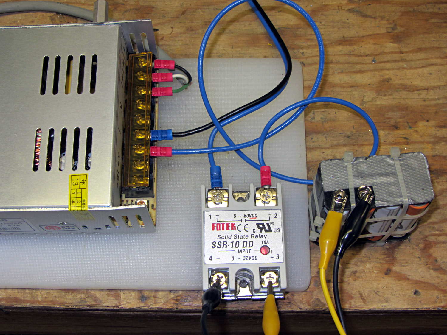
The SSR’s forward drop runs around 1.0 to 1.1 V at 4 A, which suggests a drain-source resistance near 0.25 Ω, rather more than you’d expect for a bare MOSFET, but probably about right for an up-armored device. Or it could just be a crap MOSFET inside there…
So I think the brick will wind up at about 35 V to make up for the SSR drop. The SSR will dissipate about 5 W and won’t need much heatsinking; just bolting it to an aluminum chassis may suffice.