The Smell of Molten Projects in the Morning

Ed Nisley's Blog: Shop notes, electronics, firmware, machinery, 3D printing, laser cuttery, and curiosities. Contents: 100% human thinking, 0% AI slop.

Tag: M2

Using and tweaking a Makergear M2 3D printer

  • Victoreen 710-104 Ionization Chamber: Circuit Fixture

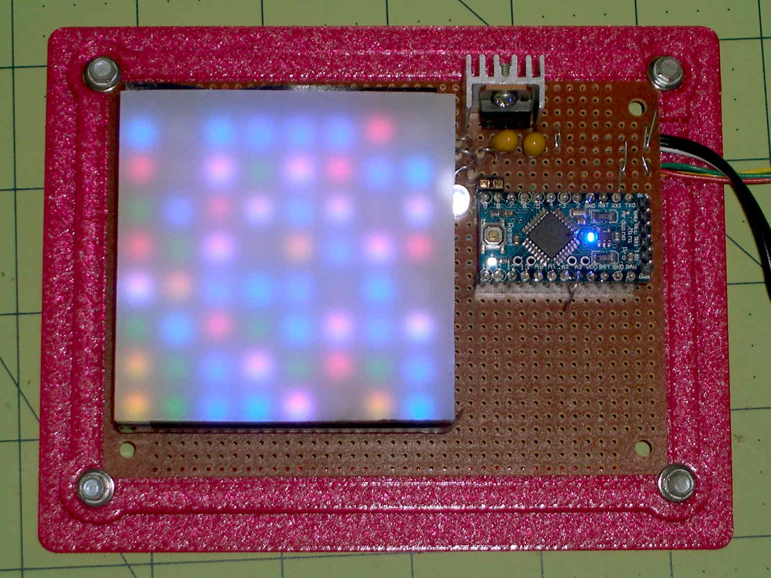
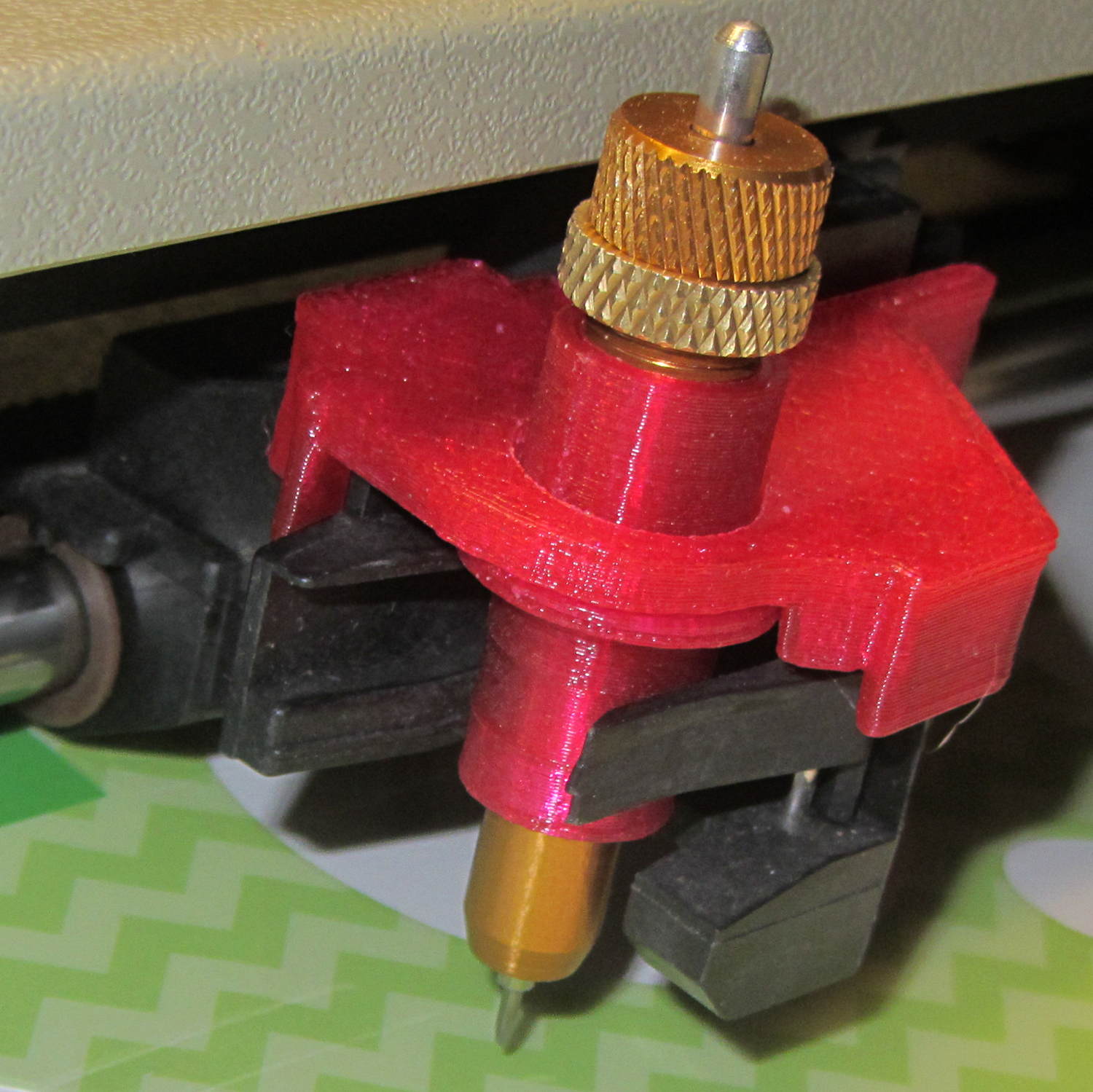
    The general idea is to put the electrometer circuitry directly atop the Victoreen 710-104 ionization chamber, so as to minimize the distance from the center collector electrode to the electrometer input. After a few false starts, this looked promising:

    Victoreen 710-104 Ionization Chamber Fittings - Show layout
    Victoreen 710-104 Ionization Chamber Fittings – Show layout

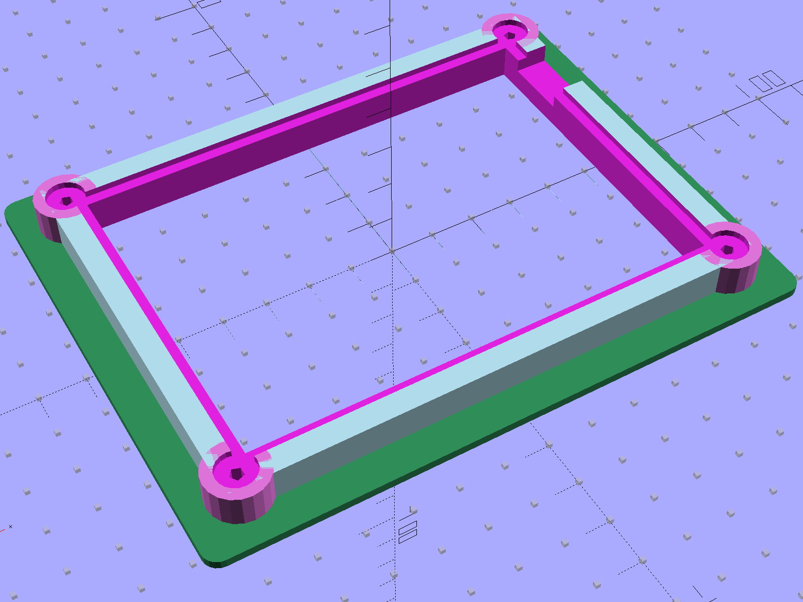
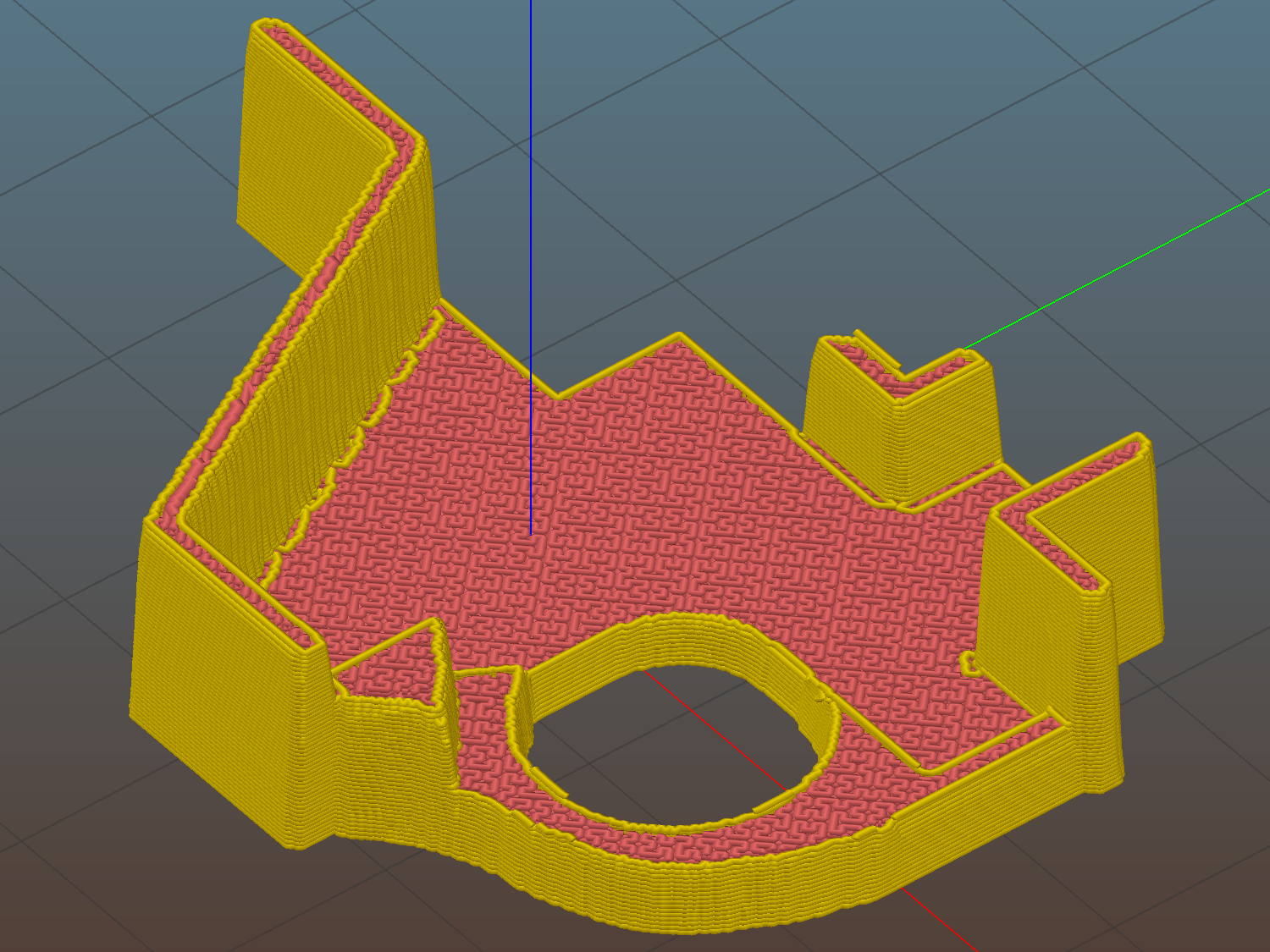
    The hexagonal circuit board fits the can so nicely that I’ll run with it, despite the over-the-top twee factor. Because it’s so hard to freehand a hex, I printed the green object as a tracing template, despite having the Slic3r preview show the parts just barely fitting on the M2 platform:

    Victoreen 710-104 Ionization Chamber Fittings - Build layout
    Victoreen 710-104 Ionization Chamber Fittings – Build layout

    Fortunately, my configuration hand is strong:

    Victoreen 710-104 Fittings - on M2 platform
    Victoreen 710-104 Fittings – on M2 platform

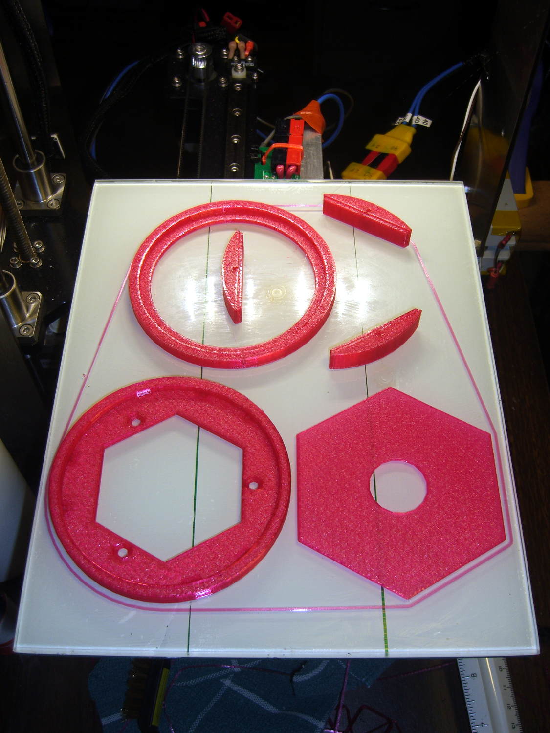
    The skirt measures 0.25±0.05 around the entire perimeter, with a slight positive bias (platform too low) along the left side and a corresponding negative bias on the right. Both sides look just fine to me.

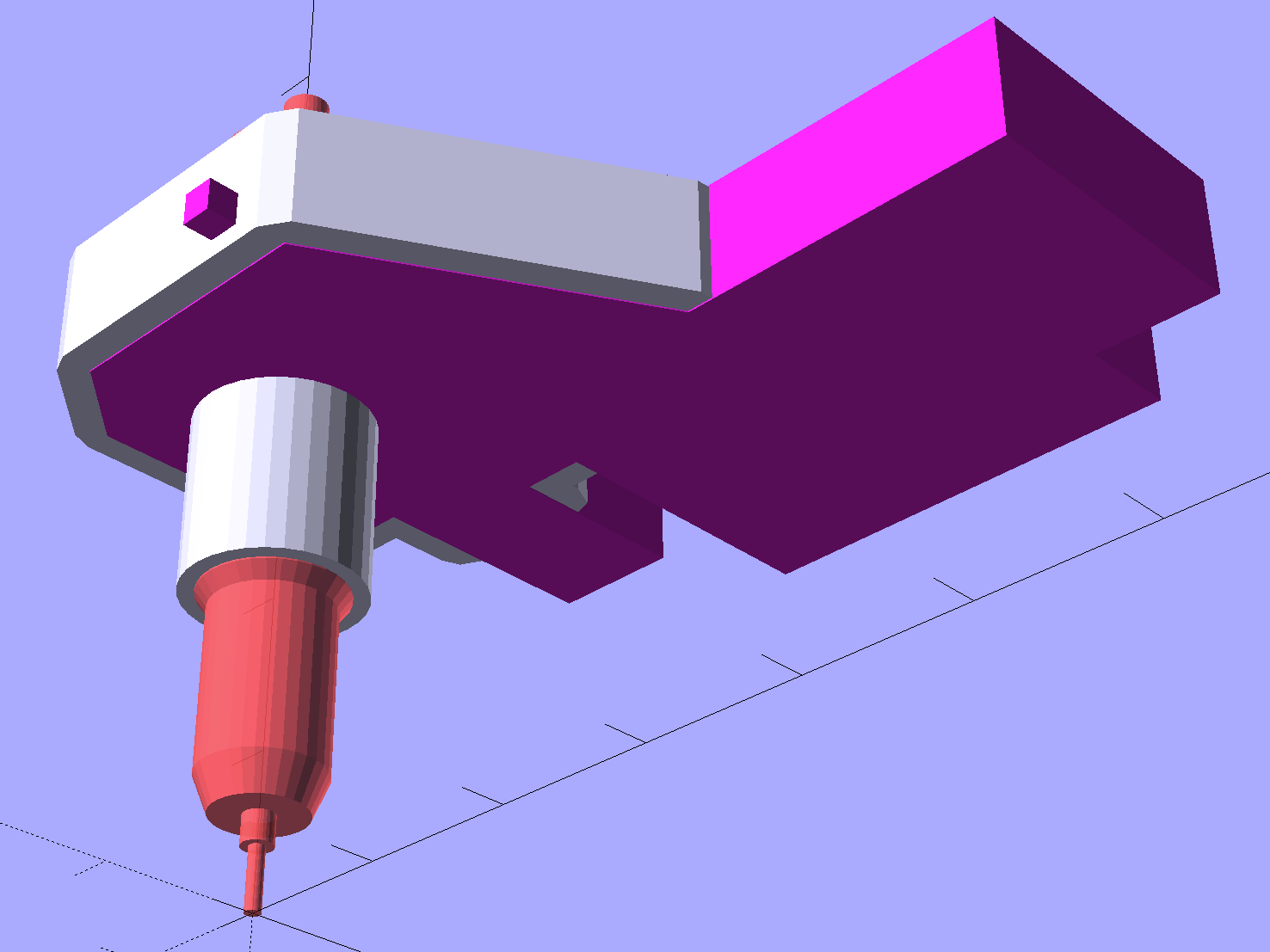
    A pair of alignment pegs hold each board support in place while gluing:

    Victoreen 710-104 Fittings - clamping
    Victoreen 710-104 Fittings – clamping

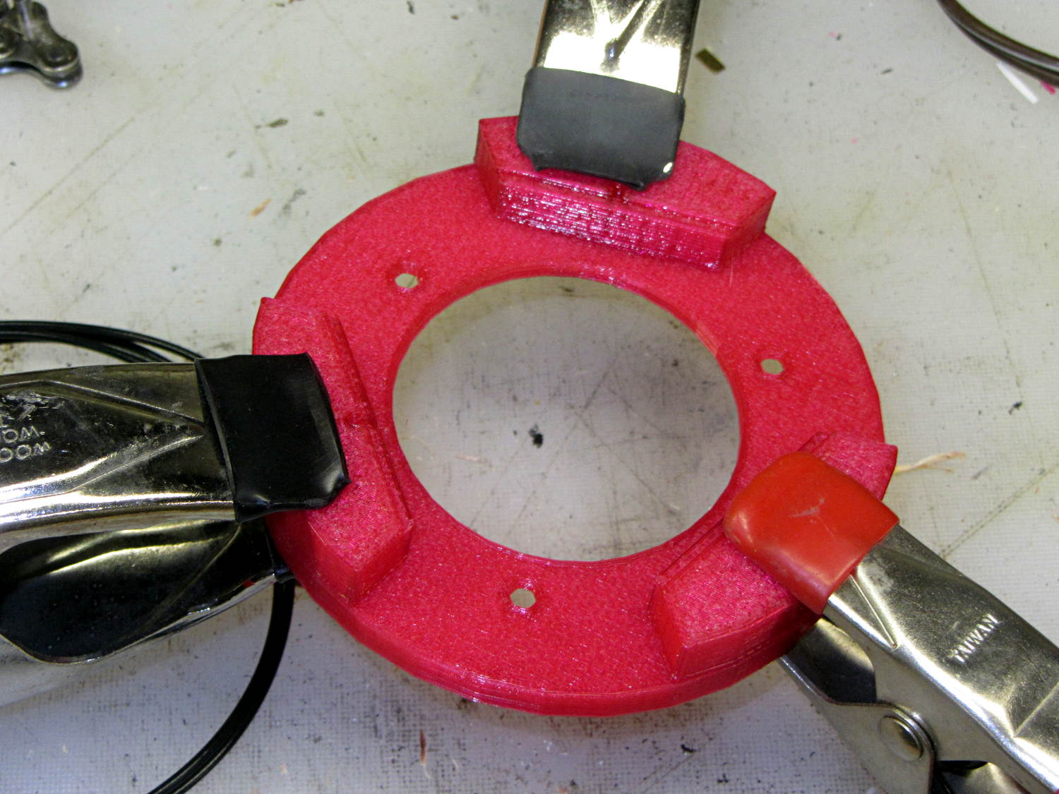
    Next time around, I’ll glue the supports with the circuit board template laid in place to ensure the edges have the proper orientation, but they came out surprisingly close just by matching the outer perimeters. Of course, I probably bandsawed / belt sanded the carefully traced hex just slightly off-kilter.

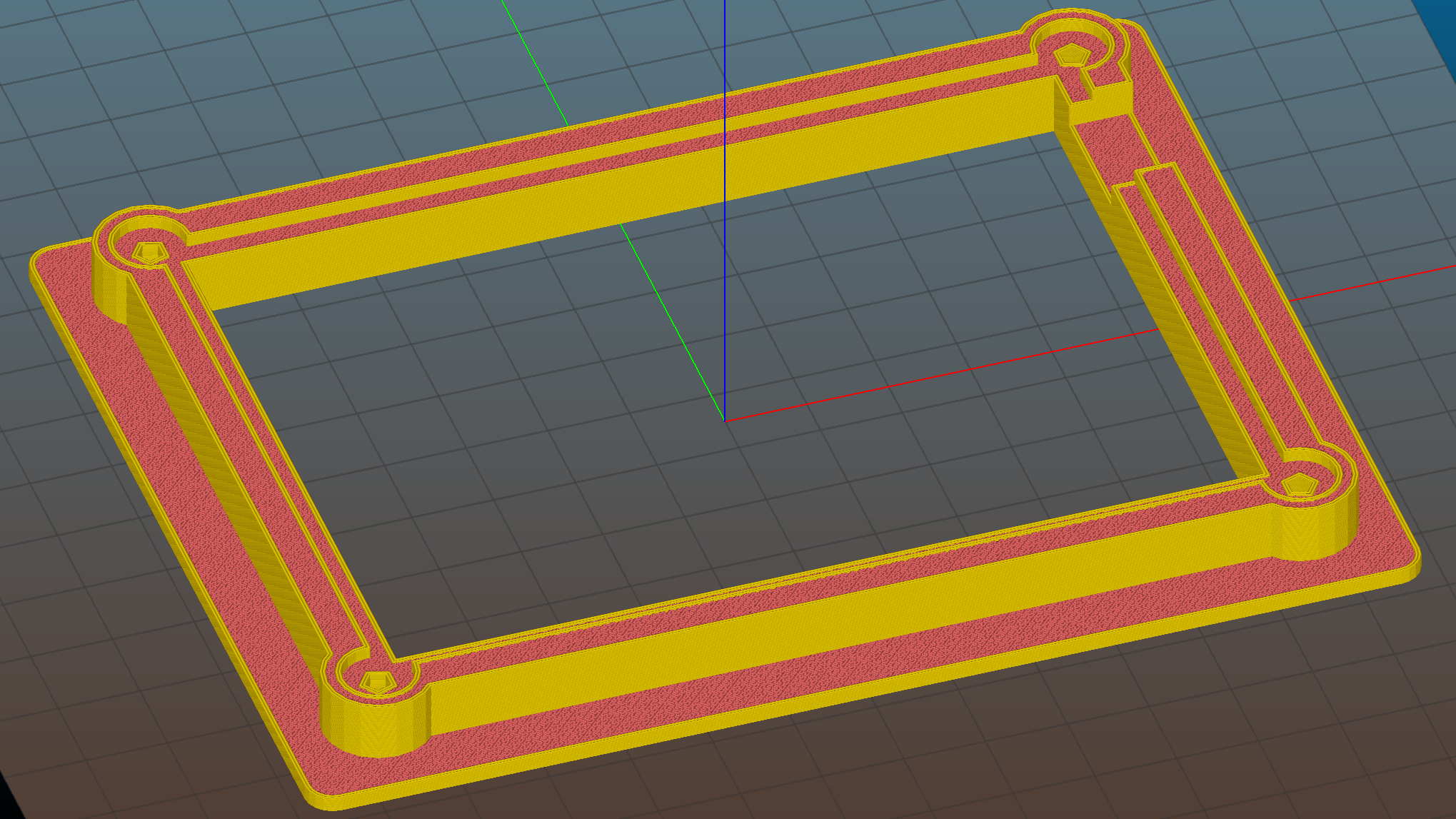
    The outer perimeter has 48 sides. Making it a multiple of three means each board support has the same pattern of sides and all will be interchangeable. Making it a multiple of four means each quadrant has the same pattern of sides and the ring looks pleasingly symmetrical. The factor-of-three is most important: you want interchangeable supports. Trust me on this.

    The bottom ring keeps the solder dimple that seals the can base off the desk, but I also stuck a quartet of rubber feet on the can for better traction.

    Here’s what it looks like with the two A23 12 V bias batteries in their holders, affixed to the can with foam tape:

    Victoreen 710-104 Fittings - assembled
    Victoreen 710-104 Fittings – assembled

    The OpenSCAD source code includes a few more tweaks:

    // Victoreen 710-104 Ionization Chamber Fittings
    // Ed Nisley KE4ZNU July 2015
    
    Layout = "Show";
    					// Show - assembled parts
    					// Build - print them out!
    					// CanCap - PCB insulator for 6-32 mounting studs
    					// CanBase - surrounding foot for ionization chamber
    					// CanLid - generic surround for either end of chamber
    					// PCB - template for cutting PCB sheet
    					// PCBBase - holder for PCB atop CanCap
    
    BuildTemplate = false;			// true to build PCB template along with everything else
    
    //- Extrusion parameters must match reality!
    //  Print with 2 shells and 3 solid layers
    
    ThreadThick = 0.25;
    ThreadWidth = 0.40;
    
    HoleWindage = 0.2;
    
    Protrusion = 0.1;			// make holes end cleanly
    
    AlignPinOD = 1.75;			// assembly alignment pins = filament dia
    
    inch = 25.4;
    
    function IntegerMultiple(Size,Unit) = Unit * ceil(Size / Unit);
    
    //- Screw sizes
    
    Tap4_40 = 0.089 * inch;
    Clear4_40 = 0.110 * inch;
    Head4_40 = 0.211 * inch;
    Head4_40Thick = 0.065 * inch;
    Nut4_40Dia = 0.228 * inch;
    Nut4_40Thick = 0.086 * inch;
    Washer4_40OD = 0.270 * inch;
    Washer4_40ID = 0.123 * inch;
    
    
    //----------------------
    // Dimensions
    
    OD = 0;											// name the subscripts
    LENGTH = 1;
    
    Chamber = [91.0 + HoleWindage,38];				// Victoreen ionization chamber dimensions
    
    Stud = [										// stud welded to ionization chamber lid
    	[6.5,IntegerMultiple(0.8,ThreadThick)],		// flat head -- generous clearance
    	[4.0,9.5],									// 6-32 screw -- ditto
    ];
    NumStuds = 3;
    StudSides = 6;									// for hole around stud
    
    BCD = 2.75 * inch;								// mounting stud bolt circle diameter
    
    PlateThick = 3.0;								// layer atop and below chamber ends
    RimHeight = 4.0;								// extending up along chamber perimeter
    WallHeight = RimHeight + PlateThick;
    WallThick = 5.0;								// thick enough to be sturdy & printable
    CapSides = 8*6;									// must be multiple of 4 & 3 to make symmetries work out right
    
    PCBFlatsOD = 85.0 + 2*ThreadWidth;				// hex dia across flats + clearance
    PCBThick = 1.1;
    PCB = [PCBFlatsOD / cos(30),PCBThick - ThreadThick];		// OD = tip-to-tip dia
    
    echo(str("Actual PCB across flats: ",PCBFlatsOD - 2*ThreadWidth));
    echo(str(" ... tip-to-tip dia: ",(PCBFlatsOD - 2*ThreadWidth)/cos(30)));
    echo(str(" ... thickness: ",PCBThick));
    
    HolderHeight = 11.0 + PCB[LENGTH];				// thick enough for PCB to clear studs
    HolderShelf = 2.0;								// shelf under PCB edge
    
    echo(str("PCB holder height: ",HolderHeight));
    echo(str(" ... across flats: ",PCBFlatsOD));
    
    //----------------------
    // Useful routines
    
    module PolyCyl(Dia,Height,ForceSides=0) {			// based on nophead's polyholes
    
      Sides = (ForceSides != 0) ? ForceSides : (ceil(Dia) + 2);
    
      FixDia = Dia / cos(180/Sides);
    
      cylinder(r=(FixDia + HoleWindage)/2,
               h=Height,
    	   $fn=Sides);
    }
    
    //- Locating pin hole with glue recess
    //  Default length is two pin diameters on each side of the split
    
    module LocatingPin(Dia=AlignPinOD,Len=0.0) {
    	
    	PinLen = (Len != 0.0) ? Len : (4*Dia);
    	
    	translate([0,0,-ThreadThick])
    		PolyCyl((Dia + 2*ThreadWidth),2*ThreadThick,4);
    
    	translate([0,0,-2*ThreadThick])
    		PolyCyl((Dia + 1*ThreadWidth),4*ThreadThick,4);
    		
    	translate([0,0,-Len/2])
    		PolyCyl(Dia,Len,4);
    
    }
    
    module ShowPegGrid(Space = 10.0,Size = 1.0) {
    
      RangeX = floor(100 / Space);
      RangeY = floor(125 / Space);
      
    	for (x=[-RangeX:RangeX])
    	  for (y=[-RangeY:RangeY])
    		translate([x*Space,y*Space,Size/2])
    		  %cube(Size,center=true);
    }
    
    //-----
    
    module CanLid() {
    	
    	difference() {
    		cylinder(d=Chamber[OD] + 2*WallThick,h=WallHeight,$fn=CapSides);
    		translate([0,0,PlateThick])
    			PolyCyl(Chamber[OD],Chamber[1],CapSides);
    	}
    	
    }
    
    module CanCap() {
    
    	difference() {
    		CanLid();
    		
    		translate([0,0,-Protrusion])											// central cutout
    //			cylinder(d=(BCD - 2*5.0),h=Chamber[LENGTH],$fn=CapSides);
    			rotate(180/6)
    				cylinder(d=BCD,h=Chamber[LENGTH],$fn=6);
    			
    		for (i=[0:(NumStuds - 1)])												// stud clearance holes
    			rotate(i*360/NumStuds)
    				translate([BCD/2,0,0])
    					rotate(180/StudSides) {
    						translate([0,0,(PlateThick - (Stud[0][LENGTH] + 2*ThreadThick))])
    							PolyCyl(Stud[0][OD],2*Stud[0][LENGTH],StudSides);
    						translate([0,0,-Protrusion])
    							PolyCyl(Stud[1][OD],2*Stud[1][LENGTH],StudSides);
    					}
    					
    		for (i=[0:(NumStuds - 1)], j=[-1,1])									// PCB holder alignment pins
    			rotate(i*360/NumStuds + j*15 + 60)
    				translate([Chamber[OD]/2,0,0])
    					rotate(180/4)
    						LocatingPin(Len=2*PlateThick - 2*ThreadThick);
    	}
    
    }
    
    module CanBase() {
    	
    	difference() {
    		CanLid();
    		translate([0,0,-Protrusion])
    			PolyCyl(Chamber[OD] - 2*5.0,Chamber[1],CapSides);
    	}
    }
    
    module PCBTemplate() {
    	
    	difference() {
    		cylinder(d=((PCBFlatsOD - 2*ThreadWidth)/cos(30)),h=max(PCB[LENGTH],3.0),$fn=6);		// actual PCB size, overly thick
    		translate([0,0,-Protrusion])
    			cylinder(d=10,h=10*PCB[LENGTH],$fn=12);
    	}
    }
    
    module PCBBase() {
    
    	difference() {
    		cylinder(d=Chamber[OD] + 2*WallThick,h=HolderHeight,$fn=CapSides);
    		
    		rotate(30) {
    			translate([0,0,-Protrusion])										// central hex
    				cylinder(d=(PCBFlatsOD - 2*HolderShelf)/cos(30),h=2*HolderHeight,$fn=6);	
    				
    			translate([0,0,HolderHeight - PCB[LENGTH]])							// hex PCB recess
    				cylinder(d=PCB[OD],h=HolderHeight,$fn=6);
    				
    			for (i=[0:NumStuds - 1])											// PCB retaining screws
    				rotate(i*120 + 30)
    					translate([(PCBFlatsOD/2 + Clear4_40/2 + ThreadWidth),0,-Protrusion])
    						rotate(180/6)
    							PolyCyl(Tap4_40,2*HolderHeight,6);
    							
    			for (i=[0:(NumStuds - 1)], j=[-1,1])								// PCB holder alignment pins
    				rotate(i*360/NumStuds + j*15 + 30)
    					translate([Chamber[OD]/2,0,0])
    						rotate(180/4)
    							LocatingPin(Len=PlateThick);
    		}
    		
    		for (i=[0:NumStuds - 1])												// segment isolation
    			rotate(i*120 - 30)
    				translate([0,0,-Protrusion]) {
    					linear_extrude(height=2*HolderHeight)
    						polygon([[0,0],[Chamber[OD],0],[Chamber[OD]*cos(60),Chamber[OD]*sin(60)]]);
    				}
    	}
    	
    
    }
    
    
    //----------------------
    // Build it
    
    ShowPegGrid();
    
    if (Layout == "CanLid") {
    	CanLid();
    }
    
    if (Layout == "CanCap") {
    	CanCap();
    }
    
    if (Layout == "CanBase") {
    	CanBase();
    }
    
    if (Layout == "PCBBase") {
    	PCBBase();
    }
    
    if (Layout == "PCB") {
    	PCBTemplate();
    }
    
    if (Layout == "Show") {
    	CanBase();
    	color("Orange",0.5)
    		translate([0,0,PlateThick + Protrusion])
    			cylinder(d=Chamber[OD],h=Chamber[LENGTH],$fn=CapSides);
    	translate([0,0,(2*PlateThick + Chamber[LENGTH] + 2*Protrusion)])
    		rotate([180,0,0])
    			CanCap();
    	translate([0,0,(2*PlateThick + Chamber[LENGTH] + 5.0)])
    		PCBBase();
    	color("Green",0.5)
    		translate([0,0,(2*PlateThick + Chamber[LENGTH] + 7.0 + HolderHeight)])
    			rotate(30)
    				PCBTemplate();
    }
    
    if (Layout == "Build") {
    	
    	if (BuildTemplate) {
    		translate([-0.50*Chamber[OD],-0.60*Chamber[OD],0])
    			CanCap();
    			
    		translate([0.55*Chamber[OD],-0.60*Chamber[OD],0])
    			rotate(30)
    				PCBTemplate();
    	}
    	else {
    		translate([-0.25*Chamber[OD],-0.60*Chamber[OD],0])
    			CanCap();
    	}
    		
    	translate([-0.25*Chamber[OD],0.60*Chamber[OD],0])
    		CanBase();
    	translate([0.25*Chamber[OD],0.60*Chamber[OD],0])
    		PCBBase();
    }
    
  • CNC Workshop 2015: Practical Solid Modeling with OpenSCAD

    HP Plotter Pen Polygon
    HP Plotter Pen Polygon

    This afternoon at the CNC Workshop, I’ll be bootstrapping folks into creating 3D-printable solid models with Openscad.

    The presentation in PDF form:

    Practical Solid Modeling for 3D Printing with OpenSCAD – CNC Workshop 2015

    The OpenSCAD source code for the exercises, in case you don’t want to type along:

    Practical Solid Modeling for 3D Printing with OpenSCAD – Models.zip.odt

    When you download that file, you’ll get something ending in .zip.odt. Rename it to remove the .odt extension, because it’s really a ZIP file; WordPress doesn’t allow users to uploads ZIP files.

  • CNC Workshop 2015: Personal 3D Printing Status Report

    Toroid Mount - Build layout
    Toroid Mount – Build layout

    If all has gone according to plan, I’m in Detroit today and will give a talk at the CNC Workshop on (my view of) the status of personal 3D printing, what to expect in the future, and what you can do with it today.

    The presentation in PDF form: 3D Printing Status 2105-06 – CNC Workshop Detroit

  • Garden Hose Valve Knobs: One Wrench To Rule Them

    A sampling of the various Y connectors and manifolds that water Mary’s gardens:

    Those little handles don’t turn nearly as easily as they should and some require far more finger pressure than Mary can exert. Lubrication being unavailing, the solution is to apply torque through a wrench, rather than fingertips, but fiddling around to match the proper wrench with the valve in hand isn’t acceptable.

    The first pass at a Universal Wrench:

    Hose Valve Knob - with measurements
    Hose Valve Knob – with measurements

    The embossed sheet (the back of my Geek Scratch Paper) carried the knob shapes & dimensions from the garden to the desk, where I measured & laid out the wrench:

    Hose Connector Knob - Build layout
    Hose Connector Knob – Build layout

    I filched the knob design from the OXO Can Opener Handle, made it somewhat taller, and applied a scale() operation to mash it into an ellipse aligned with the wrench slot. That huge hexagonal socket in the middle bridged just fine, even though the threads came out as distinct cylinders:

    Hose Connector Knob - bridge layer - Slic3r preview
    Hose Connector Knob – bridge layer – Slic3r preview

    Adding one thread width of clearance around the stem to form the socket produced a slip fit, with a dollop of fast-cure epoxy holding the pieces together.

    The wrench fits the largest valve knob with enough clearance to eliminate fiddling. A cylinder punched into the middle of the slot accommodates those teardrop handles:

    Hose Connector Knob - Show layout - bottom view
    Hose Connector Knob – Show layout – bottom view

    It’s oversized for the smallest “knob”, a vicious triangular stalk that’s murder on the fingers (and not shown here), but fits well enough that, should we deploy any of those, she’ll be ready.

    The stem diameter can’t be any larger, because the knobs on Valve 1 don’t allow any clearance. It could be more circular, but I doubt that buys anything. The open ends of the slot won’t let mulch pack into the recesses.

    I expect a wrench jaw will eventually snap off as the layers delaminate. In that case I’ll either sink a pair of steel pins into each jaw or, more likely, combine the handle & stem into one object, split the whole affair across the jaws, print the two halves, and glue them together so that the threads run in the proper direction to meet the stress.

    Be that as it may, as of right now this is The Best Thing I’ve Ever Built

    The OpenSCAD source code:

    // Hose connector knob
    // Ed Nisley KE4ZNU - June 2015
    
    Layout = "Build";				// Show Build Knob Stem
    
    //- Extrusion parameters - must match reality!
    
    ThreadThick = 0.25;
    ThreadWidth = 0.40;
    
    function IntegerMultiple(Size,Unit) = Unit * ceil(Size / Unit);
    
    Protrusion = 0.1;
    
    HoleWindage = 0.2;
    
    //------
    // Dimensions
    
    StemOD = 30.0;					// max OD for valve-to-valve clearance
    
    BossOD = 16.0;					// single-ended handle boss
    
    SlotWidth = 13.0;
    SlotHeight = 10.0;
    
    StemInset = 10.0;
    StemLength = StemInset + SlotHeight + 25.0;
    StemSides = 2*4;
    
    KnobOD1 = 70;						// maximum dia without chamfer
    KnobOD2 = 60;						// top dia
    
    KnobSides = 4*4;
    
    DomeHeight = 12;					// dome shape above lobes
    
    KnobHeight = DomeHeight + 2*SlotHeight;
    
    DomeOD = KnobOD2 + (KnobOD1 - KnobOD2)*(DomeHeight/KnobHeight);
    
    DomeArcRad = (pow(KnobHeight,2) + pow(DomeOD,2)/4) / (2*DomeHeight);
    
    //- Adjust hole diameter to make the size come out right
    
    module PolyCyl(Dia,Height,ForceSides=0) {			// based on nophead's polyholes
    
      Sides = (ForceSides != 0) ? ForceSides : (ceil(Dia) + 2);
    
      FixDia = Dia / cos(180/Sides);
    
      cylinder(r=(FixDia + HoleWindage)/2,h=Height,$fn=Sides);
    }
    
    //-- Stem for valve handles
    
    module Stem() {
    
    	difference() {
    		rotate(0*180/StemSides)
    			cylinder(d=StemOD,h=StemLength,$fn=StemSides);
    		translate([0,0,SlotHeight/2 - Protrusion/2])
    			cube([2*StemOD,SlotWidth,(SlotHeight + Protrusion)],center=true);
    		translate([0,0,-Protrusion])
    			cylinder(d=BossOD,h=SlotHeight,$fn=2*StemSides);
    	}
    
    }
    
    //-- Hand-friendly knob
    
    module KnobCap() {
    	difference() {
    		scale([1.0,0.75,1.0])
    		intersection() {
    			translate([0,0,(KnobHeight-DomeArcRad)])
    				rotate(180/KnobSides)
    					sphere(r=DomeArcRad,$fa=180/KnobSides);
    				rotate(180/KnobSides)
    					cylinder(r1=KnobOD1/2,r2=KnobOD2/2,h=KnobHeight,$fn=KnobSides);
    				rotate(180/KnobSides)
    					cylinder(r1=KnobOD2/2,r2=KnobOD1/2,h=KnobHeight,$fn=KnobSides);
    		}
    		translate([0,0,-Protrusion])
    			rotate(0*180/StemSides)
    				cylinder(d=(StemOD + 2*ThreadWidth),h=(StemInset + Protrusion),$fn=StemSides);
    	}
    }
    
    //- Build it
    
    if (Layout == "Knob")
    	KnobCap();
    
    if (Layout == "Stem")
    	Stem();
    
    if (Layout == "Build") {
    	translate([-KnobOD1/2,0,0])
    		KnobCap();
    	translate([StemOD/2,0,StemLength])
    		rotate([180,0,0])
    			Stem();
    }
    
    if (Layout == "Show") {
    	translate([0,0,0])
    		Stem();
    	translate([0,0,StemLength - StemInset])
    		KnobCap();
    }
    
  • Proto Board Holder: 80×110 mm Version

    A simple holder for 80×110 mm prototyping boards:

    Random LED Dots - circuit board
    Random LED Dots – circuit board

    It’s similar to the holder for the LED current controller board, minus the center screws, plus nicely rounded corners and a cutout for wires emerging from underneath:

    Proto board holder
    Proto board holder

    Slic3r’s Hilbert Curve infill definitely looks better than the usual straight-line pattern:

    Circuit Board Holder - Slic3r preview
    Circuit Board Holder – Slic3r preview

    The OpenSCAD source code:

    // Test support frame for Hall Effect LED Blinky Light
    // Ed Nisley KE4ZNU - Sept 2013
    
    Layout = "Fancy";				// Fancy Plain
    
    PlainColor = "LightBlue";
    
    ClampFlange = true;
    
    //- Extrusion parameters - must match reality!
    
    ThreadThick = 0.25;
    ThreadWidth = 0.40;
    
    function IntegerMultiple(Size,Unit) = Unit * ceil(Size / Unit);
    
    Protrusion = 0.1;
    
    HoleWindage = 0.2;
    
    //- Screw sizes
    
    inch = 25.4;
    
    Tap4_40 = 0.089 * inch;
    Clear4_40 = 0.110 * inch;
    Head4_40 = 0.211 * inch;
    Head4_40Thick = 0.065 * inch;
    Nut4_40Dia = 0.228 * inch;
    Nut4_40Thick = 0.086 * inch;
    Washer4_40OD = 0.270 * inch;
    Washer4_40ID = 0.123 * inch;
    
    //- PCB sizes
    
    PCBSize = [110.0,80.0,1.5];
    PCBShelf = 2.0;
    
    Clearance = 2*[ThreadWidth,ThreadWidth,0];
    
    WallThick = IntegerMultiple(5.0,ThreadWidth);
    FrameHeight = 8.0;
    
    ScrewOffset = 0.0 + Clear4_40/2;
    
    OAHeight = FrameHeight + Clearance[2] + PCBSize[2];
    
    FlangeExtension = 5.0;
    FlangeThick = IntegerMultiple(2.0,ThreadThick);
    Flange = PCBSize
    			+ 2*[ScrewOffset,ScrewOffset,0]
    			+ 2*[Washer4_40OD,Washer4_40OD,0]
    			+ [2*FlangeExtension,2*FlangeExtension,(FlangeThick - PCBSize[2])]
    			;
    
    echo("Flange: ",Flange);
    NumSides = 4*5;
    
    WireChannel = [Flange[0],15.0,3.0 + PCBSize[2]];
    WireChannelOffset = [Flange[0]/2,25.0,( + FrameHeight + PCBSize[2] - WireChannel[2]/2)];
    
    //- Adjust hole diameter to make the size come out right
    
    module PolyCyl(Dia,Height,ForceSides=0) {			// based on nophead's polyholes
    
      Sides = (ForceSides != 0) ? ForceSides : (ceil(Dia) + 2);
    
      FixDia = Dia / cos(180/Sides);
    
      cylinder(r=(FixDia + HoleWindage)/2,h=Height,$fn=Sides);
    }
    
    //- Put peg grid on build surface
    
    module ShowPegGrid(Space = 10.0,Size = 1.0) {
    
      RangeX = floor(100 / Space);
      RangeY = floor(125 / Space);
    
    	for (x=[-RangeX:RangeX])
    	  for (y=[-RangeY:RangeY])
    		translate([x*Space,y*Space,Size/2])
    		  %cube(Size,center=true);
    
    }
    
    //- Build it
    
    ShowPegGrid();
    
    difference() {
    	union() {									// body block and screw bosses
    		translate([0,0,OAHeight/2])
    			color(PlainColor)
    			cube(PCBSize + Clearance + [2*WallThick,2*WallThick,FrameHeight],center=true);
    		for (x=[-1,1], y=[-1,1]) {
    			translate([x*(PCBSize[0]/2 + ScrewOffset),
    						y*(PCBSize[1]/2 + ScrewOffset),
    						0])
    				color((Layout == "Fancy") ? "Orchid" : PlainColor)
    				cylinder(r=Washer4_40OD,h=OAHeight,$fn=NumSides);
    		}
    		if (ClampFlange)
    			color((Layout == "Fancy") ? "SeaGreen" : PlainColor)
    			linear_extrude(height=Flange[2])
    				hull()
    					for (i=[-1,1], j=[-1,1]) {
    						translate([i*(Flange[0]/2 - Washer4_40OD/2),j*(Flange[1]/2 - Washer4_40OD/2)])
    							circle(d=Washer4_40OD,$fn=NumSides);
    					}
    	}
    
    	for (x=[-1,1], y=[-1,1]) {				// screw holes and washer recesses
    		translate([x*(PCBSize[0]/2 + ScrewOffset),
    					y*(PCBSize[1]/2 + ScrewOffset),
    					-Protrusion])
    			rotate((x-1)*90)
    			PolyCyl(Tap4_40,(OAHeight + 2*Protrusion));
    		translate([x*(PCBSize[0]/2 + ScrewOffset),
    					y*(PCBSize[1]/2 + ScrewOffset),
    					OAHeight - PCBSize[2]])
    			PolyCyl(1.2*Washer4_40OD,(PCBSize[2] + Protrusion),NumSides);
    	}
    
    	translate([0,0,OAHeight/2])					// through hole below PCB
    		cube(PCBSize - 2*[PCBShelf,PCBShelf,0] + [0,0,2*OAHeight],center=true);
    
    	translate([0,0,(OAHeight - (PCBSize[2] + Clearance[2])/2 + Protrusion/2)])	// PCB pocket on top
    		cube(PCBSize + Clearance + [0,0,Protrusion],center=true);
    
    	translate(WireChannelOffset)									// clearance for cable on solder side
    		cube(WireChannel + [0,0,Protrusion],center=true);
    }
    
  • HP 7475A Plotter: Roland Knife Holder-Stabilizer

    Somewhat encouraged by the results of the height-map cap atop the plotter’s pen holder, I figured a unified knife adapter and stabilizer cap would work even better. That requires enough accuracy to build a real solid model, rather than just sketch a height map…

    Print out the the grid-overlaid image of the pen holder, then doodle coordinates & measurements all over the poor thing:

    HP 7475A Pen Holder - gridded doodle
    HP 7475A Pen Holder – gridded doodle

    Now I can toss that piece of paper…

    That, plus a bit of digital caliper work, produces a flurry of dimensions & an array of vertices:

    //-- Plotter pen holder stabilizer
    
    HolderPlateThick = 3.0;				// thickness of plate atop holder
    RimHeight = 5.0;					// rim around sides of holder
    RimThick = 2.0;
    
    HolderOrigin = [17.0,12.2,0.0];		// center of pen relative to polygon coordinates
    
    HolderZOffset = 30.0;				// top of holder in pen-down position
    HolderTopThick = 1.7;				// top of holder to top of pen flange
    HolderCylinderLength = 17.0;		// length of pen support structure
    
    HolderKnifeOffset = -2.0;			// additional downward adjustment range (not below top surface)
    
    LockScrewInset = 3.0;				// from right edge of holder plate
    LockScrewOD = 2.0;					// tap for 2.5 mm screw
    
    // Beware: update hardcoded subscripts in Stabilizer() when adding / deleting point entries 
    
    HolderPlate = [
    	[8.6,18.2],[8.6,23.9],			// 0 lower left corner of pen recess
    	[13.9,23.9],[13.9,30.0],		// 2
    //	[15.5,30.0],[15.5,25.0],		// 4 omit middle of support beam
    //	[20.4,25.0],[20.4,30.0],		// 6
    	[22.7,30.0],[22.7,27.5],		// 4
    	[35.8,27.5],[35.8,20.7],		// 6 spring box corner
    	[43.0,20.7],					// 8
    	[31.5,0.0],						// 9
    //	[24.5,0.0],[24.5,8.0],			// 10 omit pocket above pen clamp
    //	[22.5,10.0],[22.5,16.5],		// 12
    //	[20.5,18.2]						// 14
    	[13.6,0.0],						// 10
    	[8.6,5.0]						// 11
    	];
    
    BeamWidth = HolderPlate[4][0] - HolderPlate[2][0];
    

    The general idea is to extrude the overall shape of the stabilizer cap, carve out chunks to fit it onto the pen holder, then add a cylinder around the knife bearing:

    HP7475A - Roland knife stabilizer - bottom - thrown together view
    HP7475A – Roland knife stabilizer – bottom – thrown together view

    The OpenSCAD source code contains a bunch of magic numbers and indexes that pull values from the vertex array:

    module Stabilizer(SeeKnife = false) {
    
      difference() {
        union() {
          translate(-HolderOrigin)                                            // put center of pen at origin
            difference() {
                render(convexity=4)
                linear_extrude(height=(HolderPlateThick + RimHeight))         // overall flange around edges
                  offset(r=RimThick)
                      polygon(points=HolderPlate);
    
                render(convexity=4)
                translate([0,0,-Protrusion])                                  // recess for pen holder plate
                  linear_extrude(height=(RimHeight + Protrusion))
                    polygon(points=HolderPlate);
    
                translate([HolderPlate[7][0] - Protrusion,HolderPlate[7][1] - Protrusion,-Protrusion])  // trim spring box from top plate
                  cube([30,20,(RimHeight + HolderPlateThick + 2*Protrusion)]);
    
                translate([27.0,HolderPlate[6][1] - Protrusion,-Protrusion])  // trim pivot plate clearance
                  cube([30,20,(RimHeight + HolderPlateThick + 2*Protrusion)]);
    
                translate([HolderPlate[2][0],20,-Protrusion])                 // trim left support beam
                  cube([BeamWidth,20,(RimHeight + Protrusion)]);
    
                translate([HolderPlate[9][0] - LockScrewInset,RimThick,RimHeight - HolderTopThick - LockScrewOD/2])                        // lock screw on front edge
                  rotate([90,0,0])
                    rotate(180/4)
                      PolyCyl(LockScrewOD,3*RimThick);                        // hold-down screw hole
            }
    
          translate([0,0,(RimHeight - HolderCylinderLength + Protrusion)])
            cylinder(d=BodyOD,h=HolderCylinderLength + Protrusion,$fn=NumSides);  // surround knife threads
        }
    
        translate([0,0,-HolderZOffset + HolderKnifeOffset])
          if (SeeKnife)
    #        Knife();
          else
            Knife();
      }
    }
    

    A bottom view shows all the cutouts:

    HP7475A - Roland knife stabilizer - build layout
    HP7475A – Roland knife stabilizer – build layout

    The little hole in the front fits a screw that will pass under the top plate of the pen holder and prevent the cutting forces from pushing it off.

    As with the Sakura pen adapter, the knife point sits at (0,0,0) with the stabilizer cap positioned at the (estimated) top of the pen holder:

    Roland knife stabilizer - show layout
    Roland knife stabilizer – show layout

    After a few print-and-try iterations to align all the fiddly cutouts:

    HP 7475A - Roland knife stabilizer - installed
    HP 7475A – Roland knife stabilizer – installed

    The slope-topped block protruding toward you from the bottom right actuates the carousel’s pen capping mechanism; it doesn’t quite touch the side of an HP pen and is well clear of the knife holder.

    Because there’s still no depth control surrounding the knife blade, this won’t work well at all, but it should suffice for better measurements.

    The full source code is back at the beginning.

  • HP 7475A Plotter: Pen Holder Height Map Cap

    The “pen holder” in an HP 7475A plotter carries the pen across the width of the paper:

    HP 7475A - Pen Holder - overview
    HP 7475A – Pen Holder – overview

    Given that it was designed to carry pens, not knives, I wasn’t surprised that the spring-loaded finger clamping the knife adapter didn’t apply enough force to hold the adapter in place against the cutting forces. I figured a quick test of a gizmo to stabilize the adapter would be in order, even though I knew:

    • The pen holder doesn’t apply enough downward force
    • The knife adapter doesn’t have a depth-of-cut shroud around the blade

    In order to build the gizmo, I need the carrier’s dimensions…

    An overhead photo of the pen holder shows the layout in the XY plane:

    HP7475A - pen holder - top view
    HP7475A – pen holder – top view

    I shouldn’t have used graph paper as a background, because the next step was to remove the background and isolate the carrier:

    HP7475A - pen holder - top view - isolated
    HP7475A – pen holder – top view – isolated

    The carrier measures 26.8 mm front-to-back, so scaling a grid to match that dimension provides a coordinate system overlay:

    HP7475A - pen holder - top view - 1 mm grid
    HP7475A – pen holder – top view – 1 mm grid

    The (0,0) origin sits at the lower left, so you can read off all the relevant coordinates as needed.

    However, rather than go full-frontal digital, I resized the isolated image to 20 pixel/mm, turned it into a height map, and treated it like a chocolate mold or cookie cutter with gray values scaled to the desired height:

    • Black = background to be removed
    • Dark gray = 2.5 mm thick
    • Medium gray = 3.5 mm
    • Light gray = 7 mm
    • White = 10 mm

    Drawing the walls with a 40 pixel diameter pen makes them 2 mm wide at 20 pixel/mm:

    HP7475A - knife stabilizer
    HP7475A – knife stabilizer

    It’s painfully obvious why I don’t do much freehand drawing, although the knife adapter hole is supposed to be oval.

    As with cookie cutters and chocolate molds, there’s no need for that much resolution, so I rescaled it to 4 pixel/mm, saved that tiny image as a PNG file, and handed it to OpenSCAD’s surface() function to get a solid model. This being a one-off, I typed this OpenSCAD source code directly into the OpenSCAD editor on the fly, then remembered to save it (!) before shutting down:

    rotate([0,180,0])
    mirror([0,0,1])
    scale([0.25,0.25,10/100])
    difference() {
      translate([0,0,-2.0]) render(convexity=10)
        surface("/long-and-tedious-path/HP7475A - knife stabilizer - scaled.png",center=true);
      translate([0,0,-200])
        cube(400,center=true);
    }
    

    The mirror() transformation inverts the model top-to-bottom along the Z axis, compensating for the flip from drawing the height map as though the walls rise upward from the pen carrier, after which the flip() transformation puts the flat side down to make it buildable.

    The height map image conversion produces a bazillion irrelevant faces, but it’s quick and easy:

    HP7475A - Roland knife stabilizer - height map model
    HP7475A – Roland knife stabilizer – height map model

    I’ve been using Slic3r’s Hilbert Curve  pattern for top & bottom infill to get a nice textured result:

    Roland knife stabilizer - height map - Slic3r preview
    Roland knife stabilizer – height map – Slic3r preview

    Which printed just about like you’d expect:

    HP 7475A - Roland knife adapter and stabilizer - height map - bottom view
    HP 7475A – Roland knife adapter and stabilizer – height map – bottom view

    I reamed out the hole with a step drill (the HP pens are close enough to 7/16 as to make no difference here) to get the knife adapter to fit, but the walls and suchlike came out close enough.

    Then it just snapped into place:

    HP 7475A - Roland knife adapter and stabilizer - height map
    HP 7475A – Roland knife adapter and stabilizer – height map

    Actually, no, it didn’t just snap into place: some (dis)assembly was required.

    First, remove the brass knife bearing from the adapter, push the knife adapter shell into the pen holder, slide the stabilizer cap down over the adapter, press it firmly around the pen holder, reinstall the brass knife bearing, then it’s ready.

    The cuts in the green vinyl just to the left of the knife blade (in a window decoration sheet I spotted in a trash can) show that the blade can cut, albeit with some finger pressure, but the fancy red stabilizer didn’t stay stuck on the pen carrier nearly as well as I expected. A screw attachment will help with that, which calls for going all digital on those coordinates.

    But it was quick & easy…