Stainless steel socket head and button head screws add a certain techie charm to the hard drive platter mirroring the Noval tube:
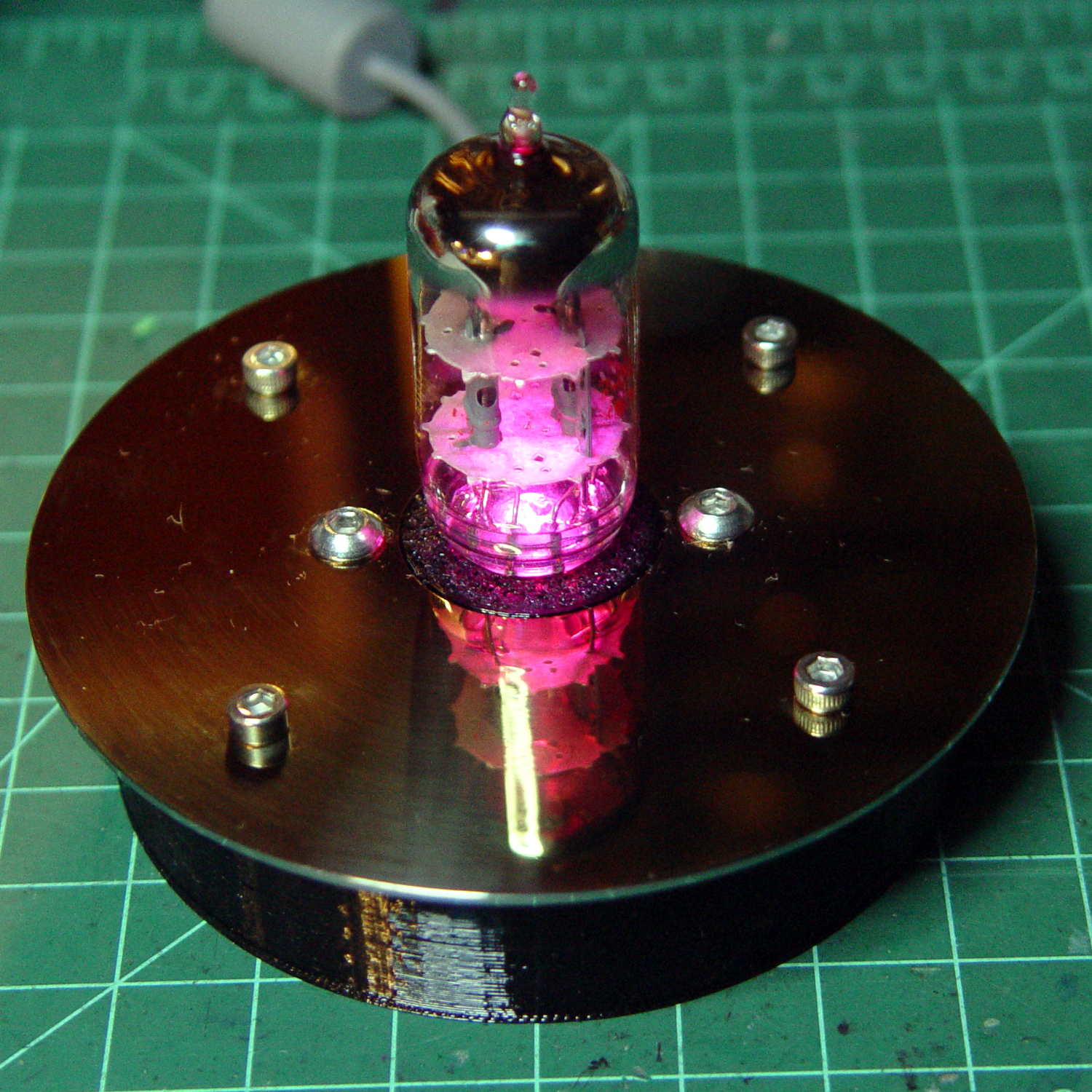
Black PETG, rather than cyan or natural filament, suppresses the socket’s glow and emphasizes the tube’s internal lighting:
The base puts the USB-to-serial adapter on the floor and stands the Pro Mini against a flat on the far wall:

A notch for the cable seems like a useful addition subtraction to the socket, because that cable tie just doesn’t look right. I used 4 mm threaded inserts, as those button head screws looked better.
The solid model looks like you’d expect:

Those are 3 mm threaded inserts, again to get the right head size screw on the platter.
The height of the base depends on the size of the socket, with the model maintaining a bit of clearance above the USB adapter. The OD depends on the platter OD, with a fixed overhang, and the insert BCD depends on the OD / insert OD / base wall thickness.
Although I’m using an Arduino Pro Mini and a separate USB-to-serial adapter, a (knockoff) Arduino Nano would be better and cheaper, although the SMD parts on the Nano’s bottom surface make it a bit thicker and less suitable for foam-tape mounting.
I drilled the platter using manual CNC:

After centering the origin on the platter hole, the hole positions (for a 71 mm BCD) use LinuxCNC’s polar notation:
g0 @[71/2]^45
g0 @[71/2]^[45+90]
g0 @[71/2]^[45+180]
g0 @[71/2]^-45
I used the Joggy Thing for manual drilling after each move; that’s easier than figuring out the appropriate g81 feed & speed.
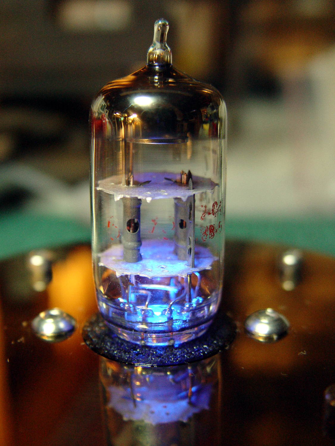
The 3D printed base still looks a bit chintzy compared with the platter, but it’s coming along.
The OpenSCAD source code as a GitHub Gist:
| // Vacuum Tube LED Lights | |
| // Ed Nisley KE4ZNU February … September 2016 | |
| Layout = "PlatterBase"; // Cap LampBase USBPort Bushings | |
| // Socket(s) (Build)FinCap Platter[Base|Fixture] | |
| DefaultSocket = "Noval"; | |
| Section = false; // cross-section the object | |
| Support = true; | |
| //- Extrusion parameters must match reality! | |
| ThreadThick = 0.25; | |
| ThreadWidth = 0.40; | |
| HoleWindage = 0.2; | |
| Protrusion = 0.1; // make holes end cleanly | |
| inch = 25.4; | |
| function IntegerMultiple(Size,Unit) = Unit * ceil(Size / Unit); | |
| //———————- | |
| // Dimensions | |
| // https://en.wikipedia.org/wiki/Tube_socket#Summary_of_Base_Details | |
| // punch & screw OC modified for drive platter chassis plate | |
| // platter = 25 mm ID | |
| // CD = 15 mm ID with raised ring at 37 mm, needs screw head clearance | |
| T_NAME = 0; // common name | |
| T_NUMPINS = 1; // total, with no allowance for keying | |
| T_PINBCD = 2; // tube pin circle diameter | |
| T_PINOD = 3; // … diameter | |
| T_PINLEN = 4; // … length (must also clear evacuation tip / spigot) | |
| T_HOLEOD = 5; // nominal panel hole from various sources | |
| T_PUNCHOD = 6; // panel hole optimized for inch-size Greenlee punches | |
| T_TUBEOD = 7; // envelope or base diameter | |
| T_PIPEOD = 8; // light pipe from LED to tube base (clear evac tip / spigot) | |
| T_SCREWOC = 9; // mounting screw holes | |
| // Name pins BCD dia length hole punch tube pipe screw | |
| TubeData = [ | |
| ["Mini7", 8, 9.53, 1.016, 7.0, 16.0, 25.0, 18.0, 5.0, 35.0], // punch 11/16, screw 22.5 OC | |
| ["Octal", 8, 17.45, 2.36, 10.0, 36.2, (8 + 1)/8 * inch, 32.0, 11.5, 47.0], // screw 39.0 OC | |
| ["Noval", 10, 11.89, 1.1016, 7.0, 22.0, 25.0 , 21.0, 7.5, 35.0], // punch 7/8, screw 28.0 OC | |
| ["Magnoval", 10, 17.45, 1.27, 9.0, 29.7, (4 + 1)/4 * inch, 46.0, 12.4, 38.2], // similar to Novar | |
| ["Duodecar", 13, 19.10, 1.05, 9.0, 32.0, (4 + 1)/4 * inch, 38.0, 12.5, 47.0], // screw 39.0 OC | |
| ]; | |
| ID = 0; | |
| OD = 1; | |
| LENGTH = 2; | |
| Pixel = [7.0,10.0,3.0]; // ID = contact patch, OD = PCB dia, LENGTH = overall thickness | |
| SocketNut = // socket mounting: threaded insert or nut recess | |
| // [3.5,5.2,7.2] // 6-32 insert | |
| [4.0,6.0,5.9] // 4 mm short insert | |
| ; | |
| NutSides = 8; | |
| SocketShim = 2*ThreadThick; // between pin holes and pixel top | |
| SocketFlange = 1.5; // rim around socket below punchout | |
| PanelThick = 1.5; // socket extension through punchout | |
| FinCutterOD = 1/8 * inch; | |
| FinCapSize = [(Pixel[OD] + 2*FinCutterOD),30.0,(10.0 + 2*Pixel[LENGTH])]; | |
| USBPCB = | |
| // [28,16,6.5] // small Sparkfun knockoff | |
| [36,18 + 1,5.8 + 0.4] // Deek-Robot fake FTDI with ISP header | |
| ; | |
| Platter = [25.0,95.0,1.26]; // hard drive platter dimensions | |
| //———————- | |
| // Useful routines | |
| module PolyCyl(Dia,Height,ForceSides=0) { // based on nophead's polyholes | |
| Sides = (ForceSides != 0) ? ForceSides : (ceil(Dia) + 2); | |
| FixDia = Dia / cos(180/Sides); | |
| cylinder(d=(FixDia + HoleWindage),h=Height,$fn=Sides); | |
| } | |
| //———————- | |
| // Tube cap | |
| CapTube = [4.0,3/16 * inch,10.0]; // brass tube for flying lead to cap LED | |
| CapSize = [Pixel[ID],(Pixel[OD] + 2.0),(CapTube[OD] + 2*Pixel[LENGTH])]; | |
| CapSides = 8*4; | |
| module Cap() { | |
| difference() { | |
| union() { | |
| cylinder(d=CapSize[OD],h=(CapSize[LENGTH]),$fn=CapSides); // main cap body | |
| translate([0,0,CapSize[LENGTH]]) // rounded top | |
| scale([1.0,1.0,0.65]) | |
| sphere(d=CapSize[OD]/cos(180/CapSides),$fn=CapSides); // cos() fixes slight undersize vs cylinder | |
| cylinder(d1=(CapSize[OD] + 2*3*ThreadWidth),d2=CapSize[OD],h=1.5*Pixel[LENGTH],$fn=CapSides); // skirt | |
| } | |
| translate([0,0,-Protrusion]) // bore for wiring to LED | |
| PolyCyl(CapSize[ID],(CapSize[LENGTH] + 3*ThreadThick + Protrusion),CapSides); | |
| translate([0,0,-Protrusion]) // PCB recess with clearance for tube dome | |
| PolyCyl(Pixel[OD],(1.5*Pixel[LENGTH] + Protrusion),CapSides); | |
| translate([0,0,(1.5*Pixel[LENGTH] – Protrusion)]) // small step + cone to retain PCB | |
| cylinder(d1=(Pixel[OD]/cos(180/CapSides) + HoleWindage),d2=Pixel[ID],h=(Pixel[LENGTH] + Protrusion),$fn=CapSides); | |
| translate([0,0,(CapSize[LENGTH] – CapTube[OD]/(2*cos(180/8)))]) // hole for brass tube holding wire loom | |
| rotate([90,0,0]) rotate(180/8) | |
| PolyCyl(CapTube[OD],CapSize[OD],8); | |
| } | |
| } | |
| //———————- | |
| // Heatsink tube cap | |
| module FinCap() { | |
| CableOD = 3.5; // cable + braid diameter | |
| BulbOD = 3.75 * inch; // bulb OD; use 10 inches for flat | |
| echo(str("Fin Cutter: ",FinCutterOD)); | |
| FinSides = 2*4; | |
| BulbRadius = BulbOD / 2; | |
| BulbDepth = BulbRadius – sqrt(pow(BulbRadius,2) – pow(FinCapSize[OD],2)/4); | |
| echo(str("Bulb OD: ",BulbOD," recess: ",BulbDepth)); | |
| NumFins = floor(PI*FinCapSize[ID] / (2*FinCutterOD)); | |
| FinAngle = 360 / NumFins; | |
| echo(str("NumFins: ",NumFins," angle: ",FinAngle," deg")); | |
| difference() { | |
| union() { | |
| cylinder(d=FinCapSize[ID],h=FinCapSize[LENGTH],$fn=2*NumFins); // main body | |
| for (i = [0:NumFins – 1]) // fins | |
| rotate(i * FinAngle) | |
| hull() { | |
| translate([FinCapSize[ID]/2,0,0]) | |
| rotate(180/FinSides) | |
| cylinder(d=FinCutterOD,h=FinCapSize[LENGTH],$fn=FinSides); | |
| translate([(FinCapSize[OD] – FinCutterOD)/2,0,0]) | |
| rotate(180/FinSides) | |
| cylinder(d=FinCutterOD,h=FinCapSize[LENGTH],$fn=FinSides); | |
| } | |
| rotate(FinAngle/2) // cable entry boss | |
| translate([FinCapSize[ID]/2,0,FinCapSize[LENGTH]/2]) | |
| cube([FinCapSize[OD]/4,FinCapSize[OD]/4,FinCapSize[LENGTH]],center=true); | |
| } | |
| for (i = [1:NumFins – 1]) // fin inner gullets, omit cable entry side | |
| rotate(i * FinAngle + FinAngle/2) // joint isn't quite perfect, but OK | |
| translate([FinCapSize[ID]/2,0,-Protrusion]) | |
| rotate(0*180/FinSides) | |
| cylinder(d=FinCutterOD/cos(180/FinSides),h=(FinCapSize[LENGTH] + 2*Protrusion),$fn=FinSides); | |
| translate([0,0,-Protrusion]) // PCB recess | |
| PolyCyl(Pixel[OD],(1.5*Pixel[LENGTH] + Protrusion),FinSides); | |
| PolyCyl(Pixel[ID],(FinCapSize[LENGTH] – 3*ThreadThick),FinSides); // bore for LED wiring | |
| translate([0,0,(FinCapSize[LENGTH] – 3*ThreadThick – 2*CableOD/(2*cos(180/8)))]) // cable inlet | |
| rotate(FinAngle/2) rotate([0,90,0]) rotate(180/8) | |
| PolyCyl(CableOD,FinCapSize[OD],8); | |
| if (BulbOD <= 10.0 * inch) // curve for top of bulb | |
| translate([0,0,-(BulbRadius – BulbDepth + 2*ThreadThick)]) // … slightly flatten tips | |
| sphere(d=BulbOD,$fn=16*FinSides); | |
| } | |
| } | |
| //———————- | |
| // Aperture for USB-to-serial adapter snout | |
| // These are all magic numbers, of course | |
| module USBPort() { | |
| translate([0,USBPCB[0]]) | |
| rotate([90,0,0]) | |
| linear_extrude(height=USBPCB[0]) | |
| polygon(points=[ | |
| [0,0], | |
| [USBPCB[1]/2,0], | |
| [USBPCB[1]/2,0.5*USBPCB[2]], | |
| [USBPCB[1]/3,USBPCB[2]], | |
| [-USBPCB[1]/3,USBPCB[2]], | |
| [-USBPCB[1]/2,0.5*USBPCB[2]], | |
| [-USBPCB[1]/2,0], | |
| ]); | |
| } | |
| //———————- | |
| // Box for Leviton ceramic lamp base | |
| module LampBase() { | |
| Insert = [3.5,5.2,7.2]; // 6-32 brass insert to match standard electrical screws | |
| Bottom = 3.0; | |
| Base = [4.0*inch,4.5*inch,20.0 + Bottom]; | |
| Sides = 12*4; | |
| Retainer = [3.5,11.0,1.0]; // flat fiber washer holding lamp base screws in place | |
| StudSides = 8; | |
| StudOC = 3.5 * inch; | |
| Stud = [Insert[OD], // insert for socket screws | |
| min(15.0,1.5*(Base[ID] – StudOC)/cos(180/StudSides)), // OD = big enough to merge with walls | |
| (Base[LENGTH] – Retainer[LENGTH])]; // leave room for retainer | |
| union() { | |
| difference() { | |
| rotate(180/Sides) | |
| cylinder(d=Base[OD],h=Base[LENGTH],$fn=Sides); | |
| rotate(180/Sides) | |
| translate([0,0,Bottom]) | |
| cylinder(d=Base[ID],h=Base[LENGTH],$fn=Sides); | |
| translate([0,-Base[OD]/2,Bottom + 1.2]) // mount on double-sided foam tape | |
| rotate(0) | |
| USBPort(); | |
| } | |
| for (i = [-1,1]) | |
| translate([i*StudOC/2,0,0]) | |
| rotate(180/StudSides) | |
| difference() { | |
| cylinder(d=Stud[OD],h=Stud[LENGTH],$fn=StudSides); | |
| translate([0,0,Bottom]) | |
| PolyCyl(Stud[ID],(Stud[LENGTH] – (Bottom – Protrusion)),6); | |
| } | |
| } | |
| } | |
| //———————- | |
| // Base for hard drive platters | |
| module PlatterBase(TubeName = DefaultSocket) { | |
| PCB = | |
| [36,18,3] // Arduino Pro Mini | |
| ; | |
| Tube = search([TubeName],TubeData,1,0)[0]; | |
| SocketHeight = Pixel[LENGTH] + SocketShim + TubeData[Tube][T_PINLEN] – PanelThick; | |
| echo(str("Base for ",TubeData[Tube][0]," socket")); | |
| Overhang = 5.5; // platter overhangs base by this much | |
| Bottom = 4*ThreadThick; | |
| Base = [(Platter[OD] – 3*Overhang), // smaller than 3.5 inch Sch 40 PVC pipe… | |
| (Platter[OD] – 2*Overhang), | |
| 2.0 + max(PCB[1],(2.0 + SocketHeight + USBPCB[2])) + Bottom]; | |
| Sides = 24*4; | |
| echo(str(" Height: ",Base[2]," mm")); | |
| Insert = // platter mounting: threaded insert or nut recess | |
| // [3.5,5.2,7.2] // 6-32 insert | |
| [3.9,5.0,8.0] // 3 mm – long insert | |
| ; | |
| NumStuds = 4; | |
| StudSides = 8; | |
| Stud = [Insert[OD], // insert for socket screws | |
| 2*Insert[OD], // OD = big enough to merge with walls | |
| Base[LENGTH]]; // leave room for retainer | |
| StudBCD = floor(Base[ID] – Stud[OD] + (Stud[OD] – Stud[ID])/2); | |
| echo(str("Platter screw BCD: ",StudBCD," mm")); | |
| PCBInset = Base[ID]/2 – sqrt(pow(Base[ID]/2,2) – pow(PCB[0],2)/4); | |
| union() { | |
| difference() { | |
| rotate(180/Sides) | |
| cylinder(d=Base[OD],h=Base[LENGTH],$fn=Sides); | |
| rotate(180/Sides) | |
| translate([0,0,Bottom]) | |
| cylinder(d=Base[ID],h=Base[LENGTH],$fn=Sides); | |
| translate([0,-Base[OD]/2,Bottom + 1.2]) // mount PCB on foam tape | |
| rotate(0) | |
| USBPort(); | |
| } | |
| for (a = [0:(NumStuds – 1)]) // platter mounting studs | |
| rotate(180/NumStuds + a*360/(NumStuds)) | |
| translate([StudBCD/2,0,0]) | |
| rotate(180/StudSides) | |
| difference() { | |
| cylinder(d=Stud[OD],h=Stud[LENGTH],$fn=2*StudSides); | |
| translate([0,0,Bottom]) | |
| PolyCyl(Stud[ID],(Stud[LENGTH] – (Bottom – Protrusion)),StudSides); | |
| } | |
| intersection() { // microcontroller PCB mounting plate | |
| rotate(180/Sides) | |
| cylinder(d=Base[OD],h=Base[LENGTH],$fn=Sides); | |
| translate([-PCB[0]/2,(Base[ID]/2 – PCBInset),0]) | |
| cube([PCB[0],Base[OD]/2,Base[LENGTH]],center=false); | |
| } | |
| difference() { | |
| intersection() { // totally ad-hoc bridge around USB opening | |
| rotate(180/Sides) | |
| cylinder(d=Base[OD],h=Base[LENGTH],$fn=Sides); | |
| translate([-1.25*USBPCB[1]/2,-(Base[ID]/2),0]) | |
| cube([1.25*USBPCB[1],2.0,Base[LENGTH]],center=false); | |
| } | |
| translate([0,-Base[OD]/2,Bottom + 1.2]) // mount PCB on foam tape | |
| rotate(0) | |
| USBPort(); | |
| } | |
| } | |
| } | |
| //———————- | |
| // Drilling fixture for disk platters | |
| module PlatterFixture() { | |
| StudOC = [1.16*inch,1.16*inch]; // Sherline tooling plate screw spacing | |
| StudClear = 5.0; | |
| BasePlate = [(20 + StudOC[0]*ceil(Platter[OD] / StudOC[0])),(Platter[OD] + 10),7.0]; | |
| PlateRound = 10.0; // corner radius | |
| difference() { | |
| hull() // basic block | |
| for (i=[-1,1], j=[-1,1]) | |
| translate([i*(BasePlate[0]/2 – PlateRound),j*(BasePlate[1]/2 – PlateRound),0]) | |
| cylinder(r=PlateRound,h=BasePlate[2],$fn=4*4); | |
| for (i=[-1:1], j=[-1:1]) // index marks | |
| translate([i*100/2,j*100/2,BasePlate[2] – 2*ThreadThick]) | |
| cylinder(d=1.5,h=1,$fn=6); | |
| for (i=[-1,1], j=[-1,0,1]) // holes for tooling plate studs | |
| translate([i*StudOC[0]*ceil(Platter[OD] / StudOC[0])/2,j*StudOC[0],-Protrusion]) | |
| PolyCyl(StudClear,BasePlate[2] + 2*Protrusion,6); | |
| translate([0,0,-Protrusion]) // center clamp hole | |
| PolyCyl(StudClear,BasePlate[2] + 2*Protrusion,6); | |
| translate([0,0,BasePlate[2] – Platter[LENGTH]]) // disk locating recess | |
| linear_extrude(height=(Platter[LENGTH] + Protrusion),convexity=2) | |
| difference() { | |
| circle(d=(Platter[OD] + 1),$fn=8*4); | |
| circle(d=Platter[ID],$fn=8*4); | |
| } | |
| translate([0,0,BasePlate[2] – 4.0]) // drilling recess | |
| linear_extrude(height=(4.0 + Protrusion),convexity=2) | |
| difference() { | |
| circle(d=(Platter[OD] – 10),$fn=8*4); | |
| circle(d=(Platter[ID] + 10),$fn=8*4); | |
| } | |
| } | |
| } | |
| //———————- | |
| // Tube Socket | |
| module Socket(Name = DefaultSocket) { | |
| NumSides = 6*4; | |
| Tube = search([Name],TubeData,1,0)[0]; | |
| echo(str("Building ",TubeData[Tube][0]," socket")); | |
| echo(str(" Punch: ",TubeData[Tube][T_PUNCHOD]," mm = ",TubeData[Tube][T_PUNCHOD]/inch," inch")); | |
| echo(str(" Screws: ",TubeData[Tube][T_SCREWOC]," mm =",TubeData[Tube][T_SCREWOC]/inch," inch OC")); | |
| OAH = Pixel[LENGTH] + SocketShim + TubeData[Tube][T_PINLEN]; | |
| BaseHeight = OAH – PanelThick; | |
| difference() { | |
| union() { | |
| linear_extrude(height=BaseHeight) // base outline | |
| hull() { | |
| circle(d=(TubeData[Tube][T_PUNCHOD] + 2*SocketFlange),$fn=NumSides); | |
| for (i=[-1,1]) | |
| translate([i*TubeData[Tube][T_SCREWOC]/2,0]) | |
| circle(d=2.0*SocketNut[OD],$fn=NumSides); | |
| } | |
| cylinder(d=TubeData[Tube][T_PUNCHOD],h=OAH,$fn=NumSides); // boss in chassis punch hole | |
| } | |
| for (i=[0:(TubeData[Tube][T_NUMPINS] – 1)]) // tube pins | |
| rotate(i*360/TubeData[Tube][T_NUMPINS]) | |
| translate([TubeData[Tube][T_PINBCD]/2,0,(OAH – TubeData[Tube][T_PINLEN])]) | |
| rotate(180/4) | |
| PolyCyl(TubeData[Tube][T_PINOD],(TubeData[Tube][T_PINLEN] + Protrusion),4); | |
| for (i=[-1,1]) // mounting screw holes & nut traps / threaded inserts | |
| translate([i*TubeData[Tube][T_SCREWOC]/2,0,-Protrusion]) { | |
| PolyCyl(SocketNut[OD],(SocketNut[LENGTH] + Protrusion),NutSides); | |
| PolyCyl(SocketNut[ID],(OAH + 2*Protrusion),NutSides); | |
| } | |
| translate([0,0,-Protrusion]) { // LED recess | |
| PolyCyl(Pixel[OD],(Pixel[LENGTH] + Protrusion),8); | |
| } | |
| translate([0,0,(Pixel[LENGTH] – Protrusion)]) { // light pipe | |
| rotate(180/TubeData[Tube][T_NUMPINS]) | |
| PolyCyl(TubeData[Tube][T_PIPEOD],(OAH + 2*Protrusion),TubeData[Tube][T_NUMPINS]); | |
| } | |
| } | |
| // Totally ad-hoc support structures … | |
| if (Support) { | |
| color("Yellow") { | |
| for (i=[-1,1]) // nut traps | |
| translate([i*TubeData[Tube][T_SCREWOC]/2,0,(SocketNut[LENGTH] – ThreadThick)/2]) | |
| for (a=[0:5]) | |
| rotate(a*30 + 15) | |
| cube([2*ThreadWidth,0.9*SocketNut[OD],(SocketNut[LENGTH] – ThreadThick)],center=true); | |
| if (Pixel[OD] > TubeData[Tube][T_PIPEOD]) // support pipe only if needed | |
| translate([0,0,(Pixel[LENGTH] – ThreadThick)/2]) | |
| for (a=[0:7]) | |
| rotate(a*22.5) | |
| cube([2*ThreadWidth,0.9*Pixel[OD],(Pixel[LENGTH] – ThreadThick)],center=true); | |
| } | |
| } | |
| } | |
| //———————- | |
| // Greenlee punch bushings | |
| module PunchBushing(Name = DefaultSocket) { | |
| PunchScrew = 9.5; | |
| BushingThick = 3.0; | |
| Tube = search([Name],TubeData,1,0)[0]; | |
| echo(str("Building ",TubeData[Tube][0]," bushing")); | |
| NumSides = 6*4; | |
| difference() { | |
| union() { | |
| cylinder(d=Platter[ID],h=BushingThick,$fn=NumSides); | |
| cylinder(d=TubeData[Tube][T_PUNCHOD],h=(BushingThick – Platter[LENGTH]),$fn=NumSides); | |
| } | |
| translate([0,0,-Protrusion]) | |
| PolyCyl(PunchScrew,5.0,8); | |
| } | |
| } | |
| //———————- | |
| // Build it | |
| if (Layout == "Cap") { | |
| if (Section) | |
| difference() { | |
| Cap(); | |
| translate([-CapSize[OD],0,CapSize[LENGTH]]) | |
| cube([2*CapSize[OD],2*CapSize[OD],3*CapSize[LENGTH]],center=true); | |
| } | |
| else | |
| Cap(); | |
| } | |
| if (Layout == "FinCap") { | |
| if (Section) render(convexity=5) | |
| difference() { | |
| FinCap(); | |
| // translate([0,-FinCapSize[OD],FinCapSize[LENGTH]]) | |
| // cube([2*FinCapSize[OD],2*FinCapSize[OD],3*FinCapSize[LENGTH]],center=true); | |
| translate([-FinCapSize[OD],0,FinCapSize[LENGTH]]) | |
| cube([2*FinCapSize[OD],2*FinCapSize[OD],3*FinCapSize[LENGTH]],center=true); | |
| } | |
| else | |
| FinCap(); | |
| } | |
| if (Layout == "BuildFinCap") | |
| translate([0,0,FinCapSize[LENGTH]]) | |
| rotate([180,0,0]) | |
| FinCap(); | |
| if (Layout == "LampBase") | |
| LampBase(); | |
| if (Layout == "PlatterBase") | |
| PlatterBase(); | |
| if (Layout == "PlatterFixture") | |
| PlatterFixture(); | |
| if (Layout == "USBPort") | |
| USBPort(); | |
| if (Layout == "Bushings") | |
| PunchBushing(); | |
| if (Layout == "Socket") | |
| if (Section) { | |
| difference() { | |
| Socket(); | |
| translate([-100/2,0,-Protrusion]) | |
| cube([100,50,50],center=false); | |
| } | |
| } | |
| else | |
| Socket(); | |
| if (Layout == "Sockets") { | |
| translate([0,50,0]) | |
| Socket("Mini7"); | |
| translate([0,20,0]) | |
| Socket("Octal"); | |
| translate([0,-15,0]) | |
| Socket("Duodecar"); | |
| translate([0,-50,0]) | |
| Socket("Noval"); | |
| translate([0,-85,0]) | |
| Socket("Magnoval");} |

Comments
8 responses to “Vacuum Tube LEDs: Hard Drive Platter Base”
Would that it were so!
I type G-Code directly into the MDI panel and use the Joggy Thing for alignment & touchoff. That process neatly combines the accuracy of CNC positioning with the impromptu “Oh, shit!” of manual milling… [sigh]
How about chucking the base in the lathe and giving it a light finishing cut to get rid of layer transitions? Afterwards you could finish it with a coat of black paint from a spray can.
I’ve never been satisfied with machining 3D printed objects, probably because I don’t make them rigid enough to withstand much in the way of external force. Perhaps a mandrel to support / clamp the inside?
I should do a couple of test pieces just to see how it works, now that I have nice sharp carbide inserts…
I’m unclear what that cable tie is wrapped around, it looks like it’s just floating on the wire. You could, theoretically, print the socket and the base together, in which case you’d only need one set of screws to hold the platter on as well.
Half a dozen screw threads stick out beyond the brass insert: just enough for the cable tie to not quite fall off. It’s sooo half-assed that the socket model now has two slots bracketing the LED.
I haven’t figured out how to slide the LED into the middle of a socket that grows out of the base: a slot would (probably) require impossible-to-remove support. Plus, the USB adapter sits in the air gap under the socket; the soon-to-arrive Nano boards may suggest a different arrangement.
That poor platter has way too many screw holes, fer shure…
[…] drilling the platter for a Noval tube, I finally made a fixture to hold the platters firmly, but gently, in the proper position for […]
[…] out a base to fit the Duodecar socket and assembling all the […]