Ed Nisley's Blog: Shop notes, electronics, firmware, machinery, 3D printing, laser cuttery, and curiosities. Contents: 100% human thinking, 0% AI slop.
The topic of function generators came up at Squidwrench a while ago (Sophi was tinkering with LCD shutters) and I finally picked up one of those JYE Tech FG085 DDS function generators to see how they work:
FG085 Fn Gen – in case
Short answer: adequate, if you’re not too fussy.
The board arrived with a bizarre solder defect. It seems a solder stalk yanked one terminal off a ceramic SMD caps:
FG085 – Solder stalk – C26
The schematic and adjacent parts suggested the victim was a 10 uF cap, so I replaced it with one from my stash that worked fine.
However, after soldering enough of the switches to do something useful, the board wouldn’t power up. With a bit of poking around, I discovered the power jack had +15 V from the wall wart, but the center terminals on the DPDT power switch that should have been connected to the jack showed maybe 0.3 V. Jumpering around the failed via and a short trace on the bottom surface let the board power up correctly:
FG085 – Jumpered power trace
If you’re building one of these, solder one pin of each switch, push all the switch caps in place, shove the faceplate over all of them, tape it to the PCB, make sure all the switches are push-able, then solder the remainder of the switch pins. If you do them one by one, you’re certain to end up with a few mis-aligned switches that will either prevent the faceplate from sliding over them or wedge firmly against the side of their assigned hole. Just sayin’.
I tweaked the dimensions slightly to fit the (slightly larger, possibly new, maybe tolerance-eased) front panel, but the bottom mounting screw hole spacing depends on the front panel size, not a specific set of dimensions, leading me to relocate those holes by abrasive adjustment. I didn’t bother with the lid (which doesn’t clear the BNC jack anyway) or the printed plastic feet (having a supply of silicone rubber feet).
The fancy vent gridwork along the sides printed surprisingly well, even in PETG. I’d have gone with larger slots, although I doubt the thing really needs vents in the first place.
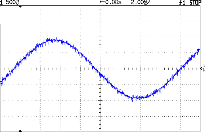
The DDS sine wave output is rough, to say the least:
FG085 Fn Gen – 60 kHz sine
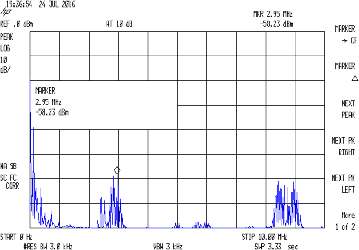
The spectrum shows oodles of harmonic content:
FG085 Fn Gen – 60 kHz sine – spectrum
A closer look:
FG085 Fn Gen – 60 kHz sine – spectrum – detail
Stepping back a bit shows harmonics of (and around) the 2.5 MHz DDS sampling frequency:
FG085 Fn Gen – 60 kHz sine – spectrum – 10 MHz
For comparison, my old Fordham FG-801 analog function generator has nice smooth harmonics:
FG-801 Fn Gen – 60 kHz sine – spectrum
Closer in:
FG-801 Fn Gen – 60 kHz sine – spectrum – detail
Of course, that crusty old analog dial doesn’t provide nearly the set-ability of a nice digital display.
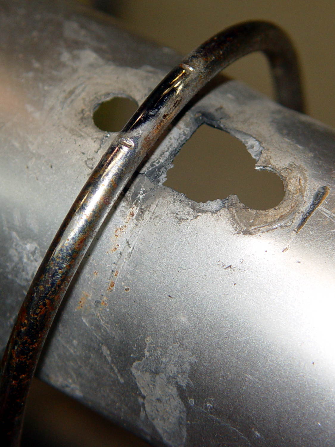
We agreed that repairing the failed flag ferrule made the trailer much quieter, but it still seemed far more rattly than we remembered. It just had to be the fender, somehow, and eventually this appeared:
BOB Yak Fender Mount – fractures
The obviously missing piece of the fender fell out in my hand; the similar chunk just beyond the wire arch fell out after I took the pictures. Yes, the wire has indented the fender.
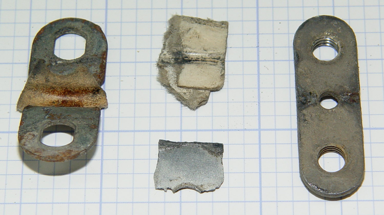
The arch supports the aluminum fender, with a pair of (flat) steel plates clamping the wire to the fender:
BOB Yak Fender Mount – screw plates and pads
The cardboard scraps show I fixed a rattle in the distant past.
Being aluminum, the fender can’t have a replacement piece brazed in place and, given the compound curves, I wasn’t up for the requisite fancy sheet metal work.
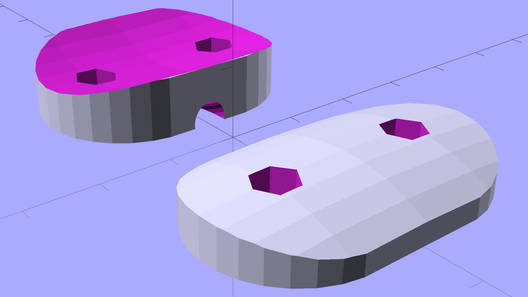
Instead, a bit of math produces a pair of shapes:
BOB Yak Fender Mount – solid model
In this case, we know the curve radii, so the chord equation gives the depth of the curve across the (known) width & length of the plates; the maximum of those values sets the additional thickness required for the plates. The curves turn out to be rather steep, given the usual layer thickness and plate sizes, which gives them a weird angular look that absolutely doesn’t matter when pressed firmly against the fender:
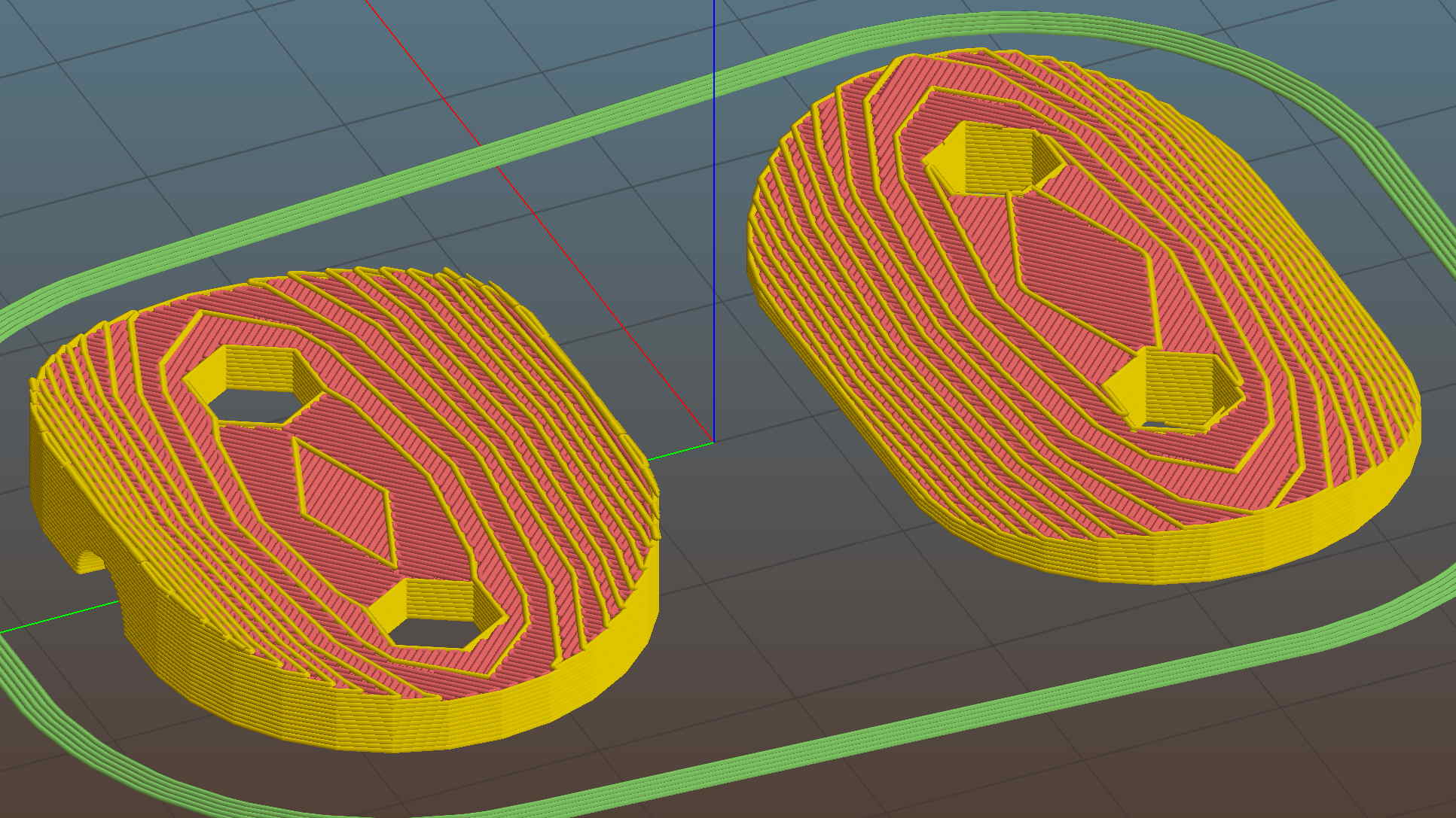
BOB Yak Fender Mount – Slic3r preview
The computations required to fit Hilbert Curve surface infill into those small exposed areas took basically forever; given that nobody will ever see them, I used the traditional linear infill pattern. A 15% 3D Honeycomb interior infill turned them into rigid parts.
The notch in the outer plate (top left, seen notch-side-down) accommodates the support wire:
BOB Yak Fender Mount – outer
The upper surface would look better with chamfered edges, but that’s in the nature of fine tuning. That part must print with its top surface downward: an unsupported (shallow) chamfer would produce horrible surface finish and life is too short for fussing with support. Given the surrounding rust & dings, worrying about aesthetics seems bootless.
The original screws weren’t quite long enough to reach through the plastic plates, so I dipped into my shiny-new assortment of stainless steel socket head cap screws. Although the (uncut) M5x16 screws seem to protrude dangerously far from the inner plate, there’s another inch of air between those screws and the tire tread:
BOB Yak Fender Mount – inner
Given the increase in bearing area, that part of the fender shouldn’t fracture for another decade or two.
I loves me my M2 3D printer …
The OpenSCAD source code as a GitHub Gist:
This file contains hidden or bidirectional Unicode text that may be interpreted or compiled differently than what appears below. To review, open the file in an editor that reveals hidden Unicode characters.
Learn more about bidirectional Unicode characters
Our standard dishwasher loadout changed a while back, so I ran off more protectors to fill the bottom rack. The crystalline look of natural PETG is probably wasted in there, even though it puts the old, rather yellowed, PLA protectors to shame:
Dishwasher Rack Protectors – old PLA new PETG
Dollops of silicone sealant hold them in place: the bigger the blob, the better the job.
We don’t activate the drying heater, so the plastic doesn’t get exposed to absurdly high temperatures. As nearly as I can tell, those PLA protectors remain in fine physical condition, even though they’re turning an odd color.
The support structures peeled out easily with a fingernail pull:
Dishwasher Rack Protectors – 0.20 mm PETG bridging – detail
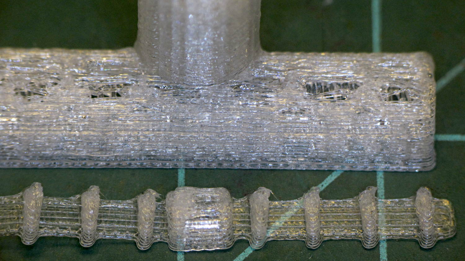
PETG doesn’t bridge well, as shown by the gaps between the support ridges. Those 0.20 mm layers seemed skimpy for lightly supported PETG, so I ran another set at 0.25 mm:
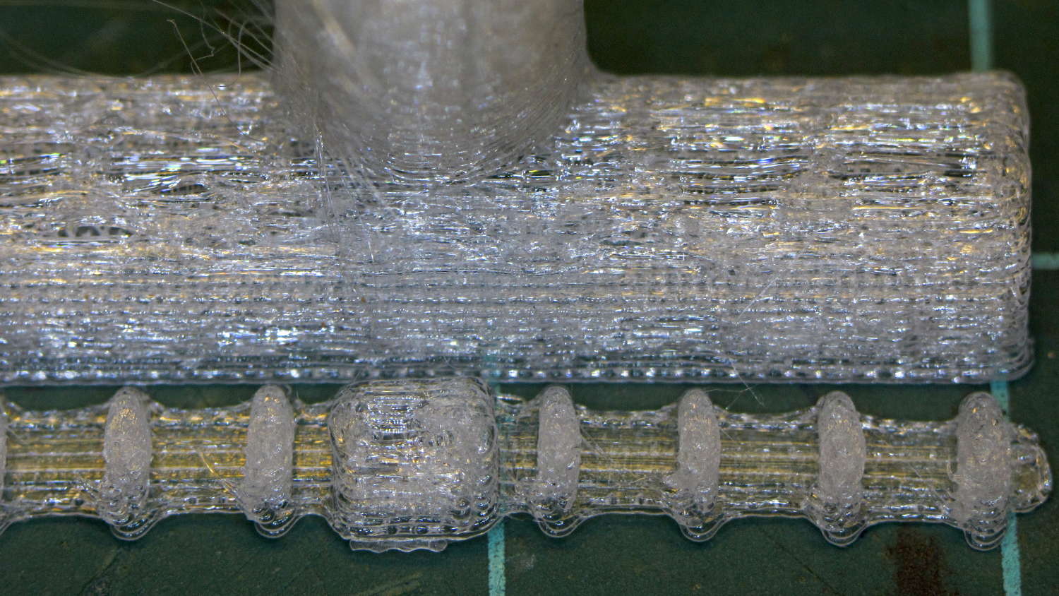
Dishwasher Rack Protectors – 0.25 mm PETG bridging – detail
Not quite enough improvement for a Happy Dance, although fine for the application.
We look forward to seeing what grows in those little crevices…
It turns out that the dual-core Intel Atom Inside an old Dell Mini 10 isn’t up to the demands of rendering modern web design; disk I/O speed has nothing to do with the CPU’s (lack of) ability to chew through multiple layers of cruft adorning what used to be straightforward static HTML.
So, equipped with Linux Mint / XFCE, it’s now found a new purpose in life:
SnowWhite back in action
In truth, an Atom isn’t quite up to the demands of modern 3D printing, either, at least in terms of processing a huge G-Code file into a layer-by-layer path preview. Fortunately, Pronterface doesn’t generate the preview until you ask for it: arranging the UI to put the preview on a separate tab eliminates that problem.
The Mini 10 can dribble G-Code into the printer just fine and looks much cuter than the hulking laptop in the background.
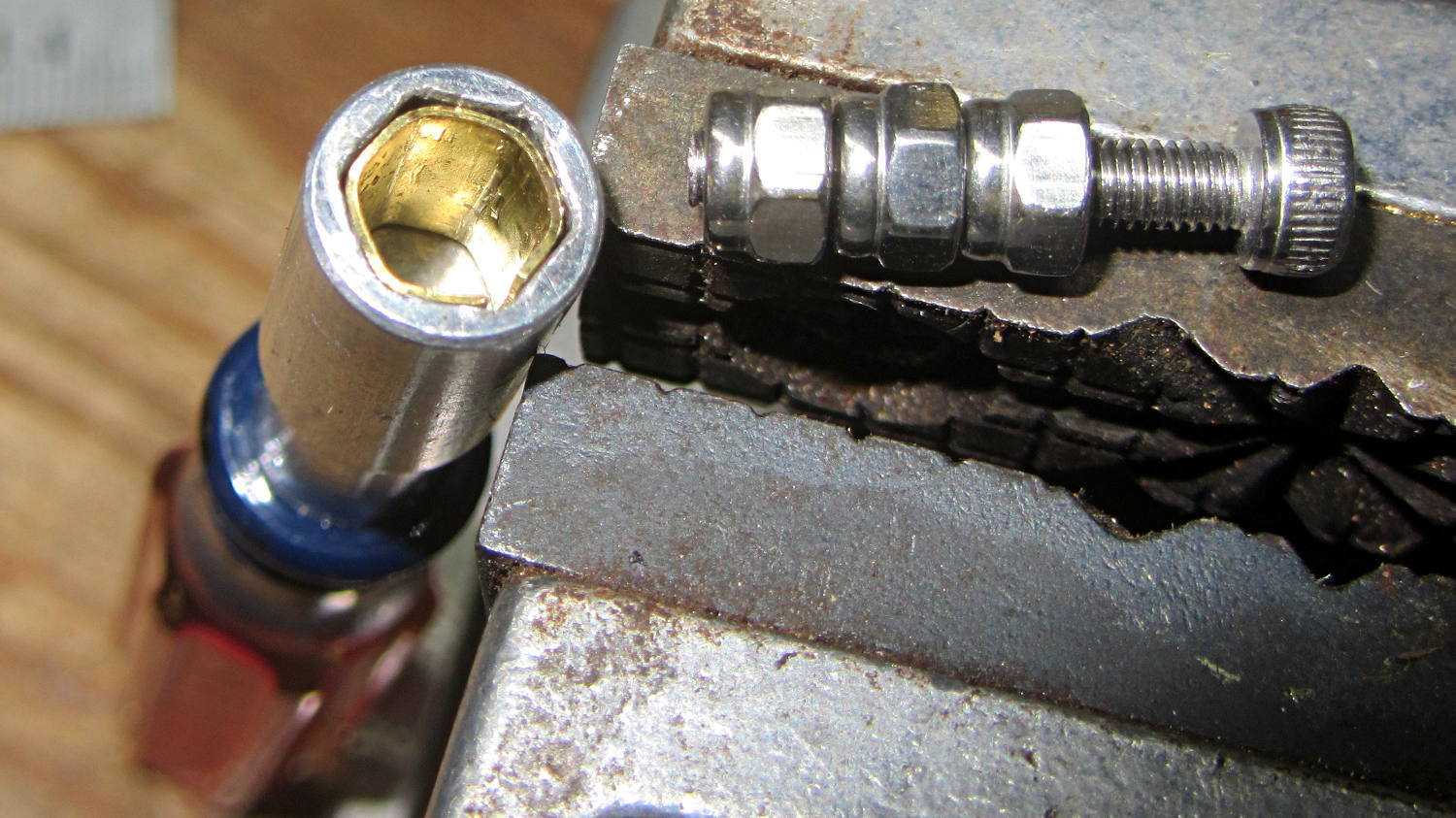
A tiny 1/4 inch hex driver handle appeared from the far reaches of a drawer, sporting a handle better suited for tweaking the 3 mm adjusting nuts on the bottom of the M2’s platform than applying actual torque to real fasteners. Rather than breaking a set of nut drivers, I made a simple brass shim to soak up the difference between the handle’s 6.5 mm ID hex and the 5.5 mm OD of the nuts:
Hex driver shim – installed
That’s 15 mil = 0.40 mm shimstock to leave enough clearance for my crude forming technique.
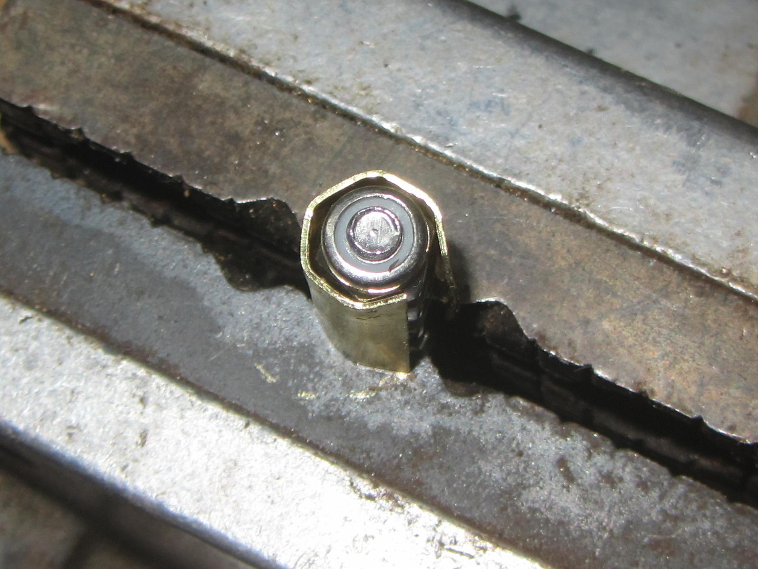
Which technique consisted of making a “mandrel” by lining up a trio of Nyloc nuts on a screw, snipping off a suitable shimstock rectangle, and squashing it into shape with parallel-jaw pliers:
Hex driver shim – forming
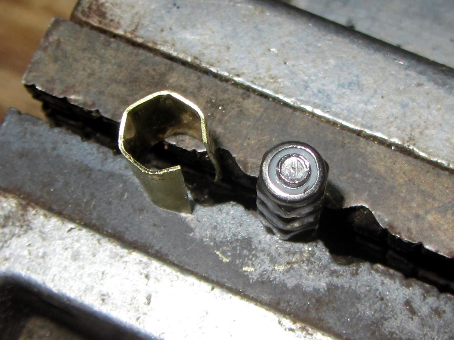
As you’d expect, the shimstock hex came out larger & uglier than the mandrel:
Hex driver shim – formed
But that doesn’t matter after it’s tucked inside the driver; it works perfectly.
Long ago, Mary picked out a PTT switch with a raised, square post that provided a distinct shape and positive tactile feedback:
PTT Button – bare post
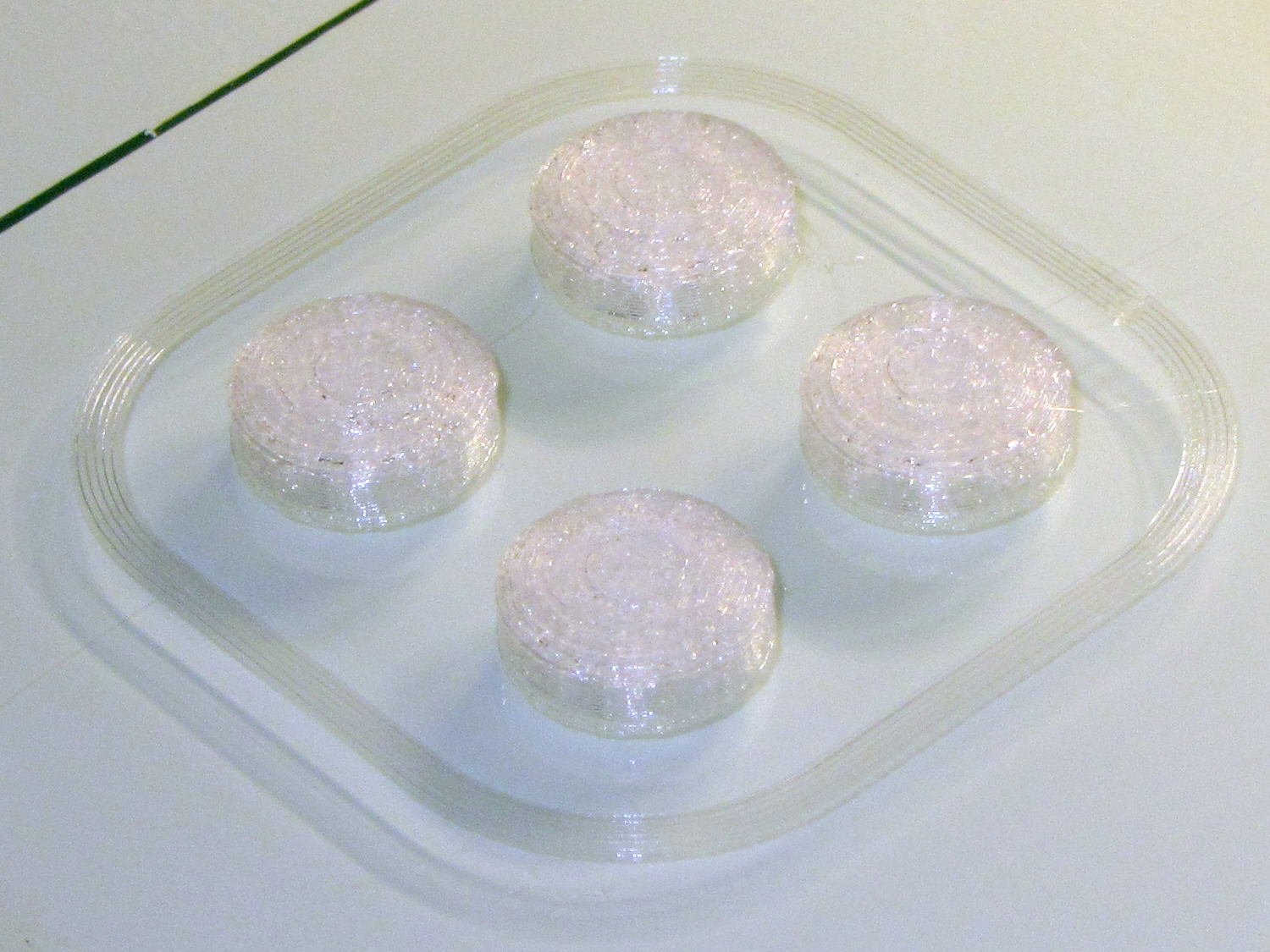
Time passes, she dinged her thumb in the garden, and asked for a more rounded button. I have some switches with rounded caps, but replacing the existing switch looked a lot like work, sooooo:
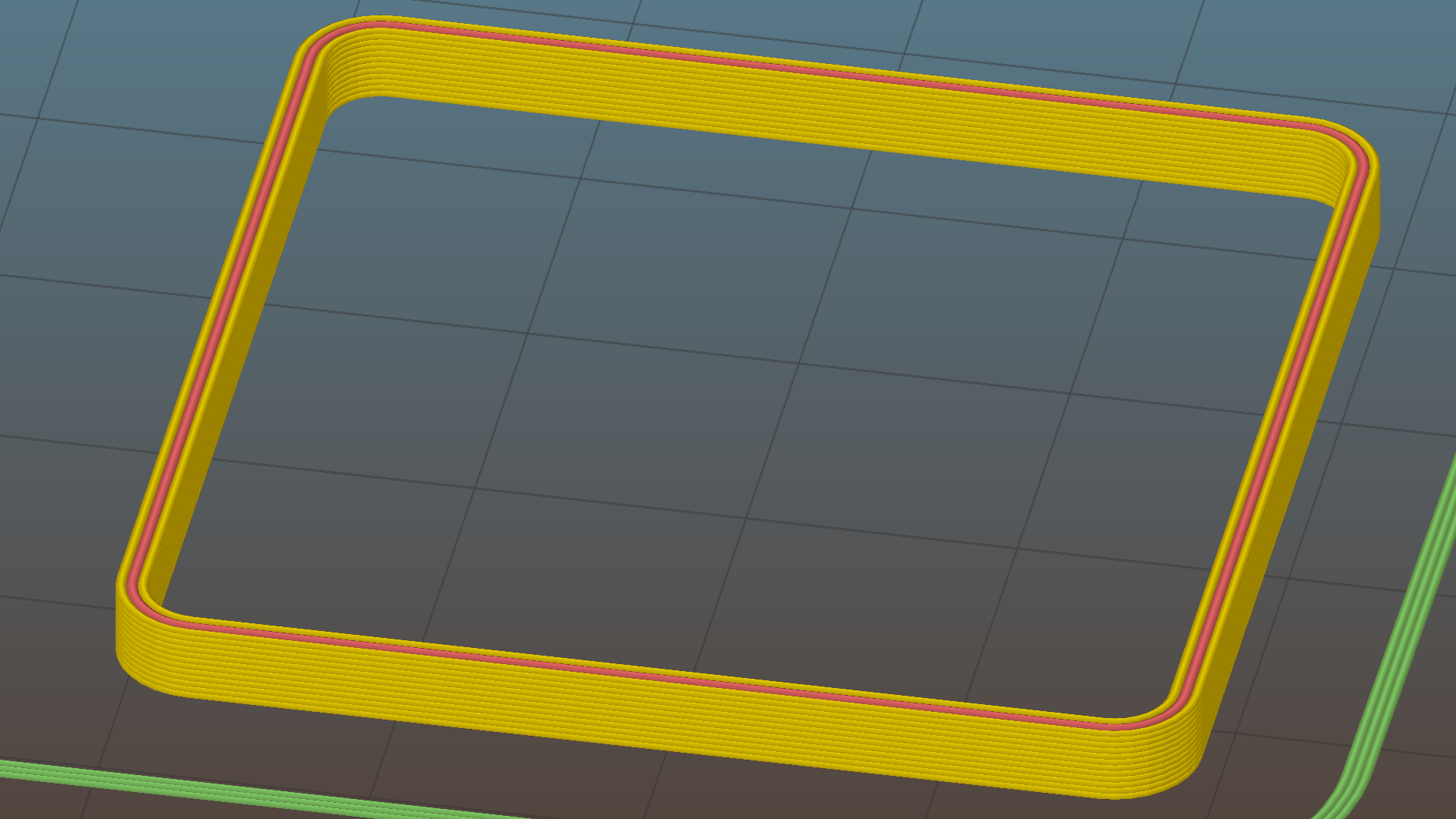
PTT Button Cap – Slic3r preview
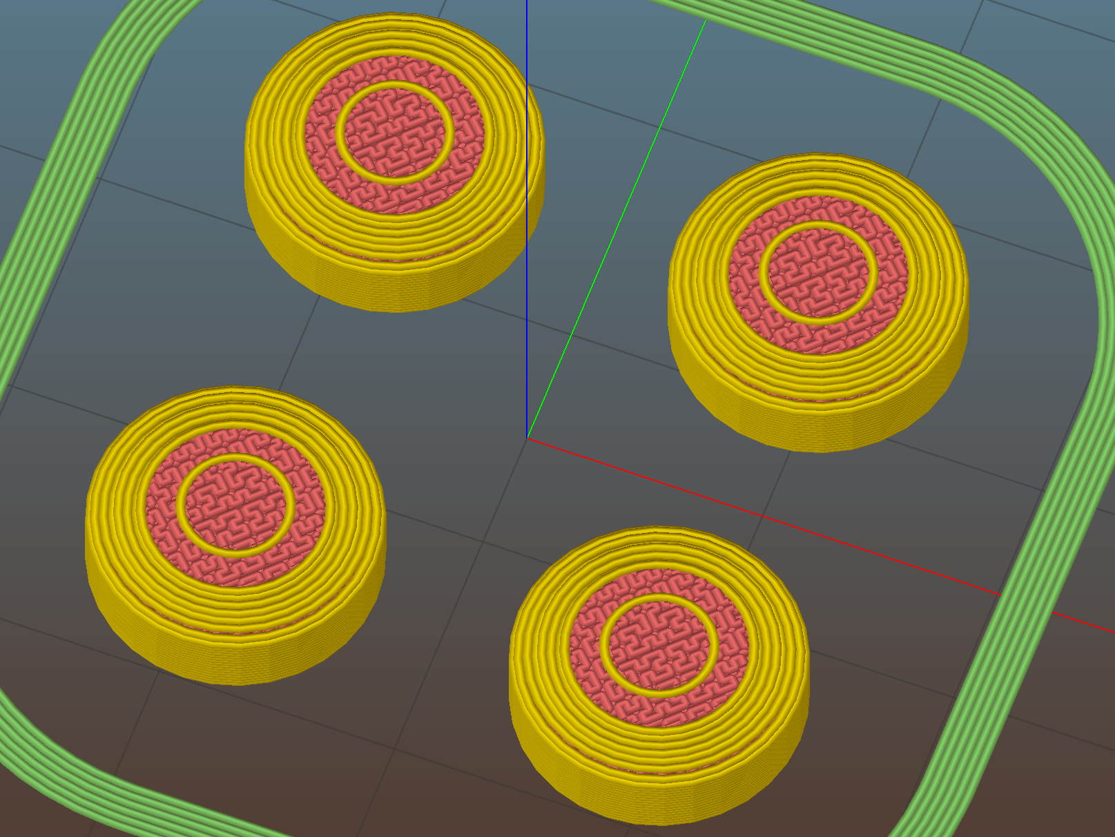
As with all small objects, building them four at a time gives the plastic in each one time to cool before slapping the next layer on top:
PTT Button – on platform
The hole in the cap is 0.2 mm oversize, which results in a snug press fit on the small ridges barely visible around the post in the first image:
PTT Button – rounded cap
Rather than compute the chord covering the surface, I just resized a sphere to twice the desired dome height (picked as 6 threads, just for convenience) and plunked it atop a cylinder. Remember to expand the sphere diameter by 1/cos(180/sides) to make it match the cylinder and force both to have the same number of sides.
This file contains hidden or bidirectional Unicode text that may be interpreted or compiled differently than what appears below. To review, open the file in an editor that reveals hidden Unicode characters.
Learn more about bidirectional Unicode characters
As part of setting the Makergear M2 up after The Great Cleanout, I ran off a set of thinwall calibration squares that showed the left rear corner was high by 0.12 mm: the square in that corner measured 2.88 mm, rather than the intended 3.0 mm. The walls were 0.43 mm, about 10% above the nominal 0.40 mm.
I tightened the rear platform screw by a bit under 1/12 turn, less than half a flat on the hex nut, and dialed the Extrusion Multiplier back by 10%. The next set of squares, set up for walls made of three parallel threads, came out with heights within 0.08 mm of each other and 1.15 mm thick (rather than the nominal 1.20 mm).
They’re 40 mm on a side, mostly to produce bigger handouts for the next show-n-tell:
Thinwall open box – array on platform – 3w 40 3.0
Letting it sit for a few days and running the same G-Code produced heights within 0.07 mm and wall thickness at 1.18, which I defined to be Good Enough.
Recent versions of Slic3r have been adjusting the various thread widths on the fly, as I’ve let everything except the basic extrusion width go with the default values. As a result, setting the wall width to 2 threads (0.80 mm) can produce an extremely thin third thread between the two perimeter threads that doesn’t extrude well. Making the wall three threads wide works much better:
Calibration Box – open – 3w 40 3.0
The slicing algorithms may be smart enough to make all the tricks I’ve learned completely obsolete; that’s fine with me!