I’d originally secured the rear fender to the steel strap connecting the chainstays on Mary’s Tour Easy with a cable tie: small, simple, light weight, reliable. Unfortunately, that put the end of the fender just slightly lower than the strap and, I fear, sprayed water all over the strap, where it worked its way through a paint flaw and rusted the steel under the paint. A simple metal clip would chew its way through the pain[t] on the strap, so, seeing as how we’re living in the future…
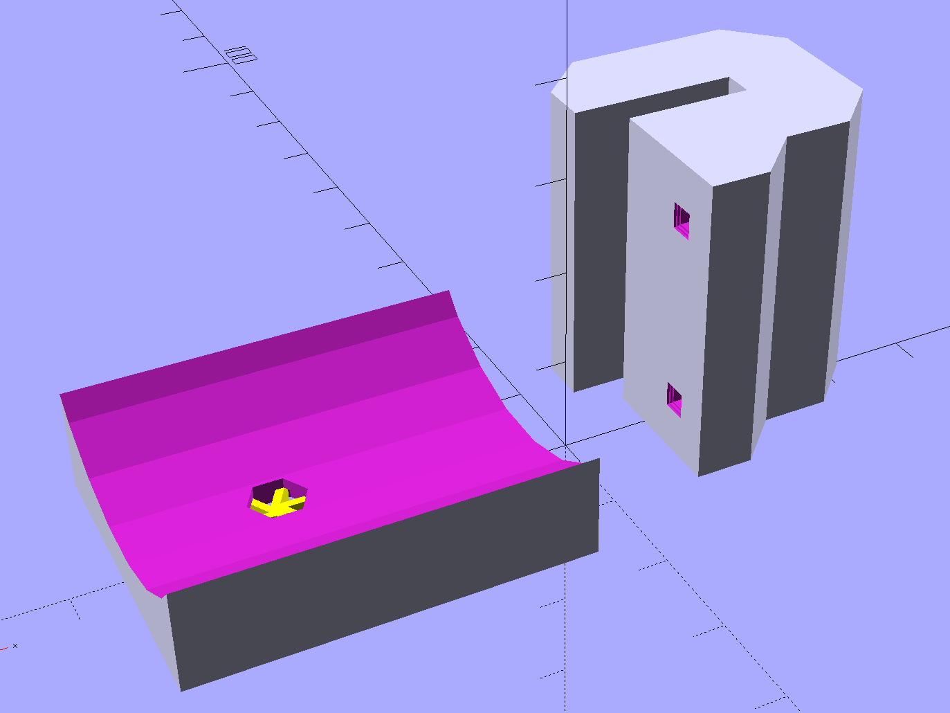
The C-shaped block on the top grips the steel cross-strap, the trough fits the fender’s curve, the little spider supports the inside of the nut recess, and a pair of alignment pin holes (one visible) help during gluing:

Although it’s tempting to 3D print both parts as a single unit, laying them out like this aligns the threads for best strength in each piece:
Pressing the bracket on the glass slab (flat side up, nubblies on the bottom) with the clamps in place finished the job. The slightly crushed support spider from the nut recess sits in the foreground:

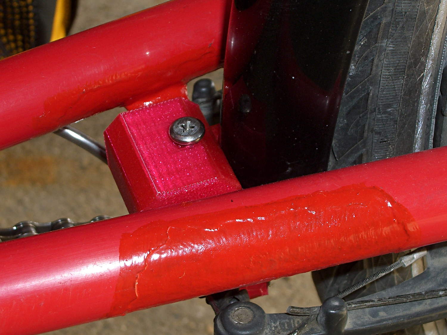
Magenta PETG matches the red Tour Easy paint surprisingly well:
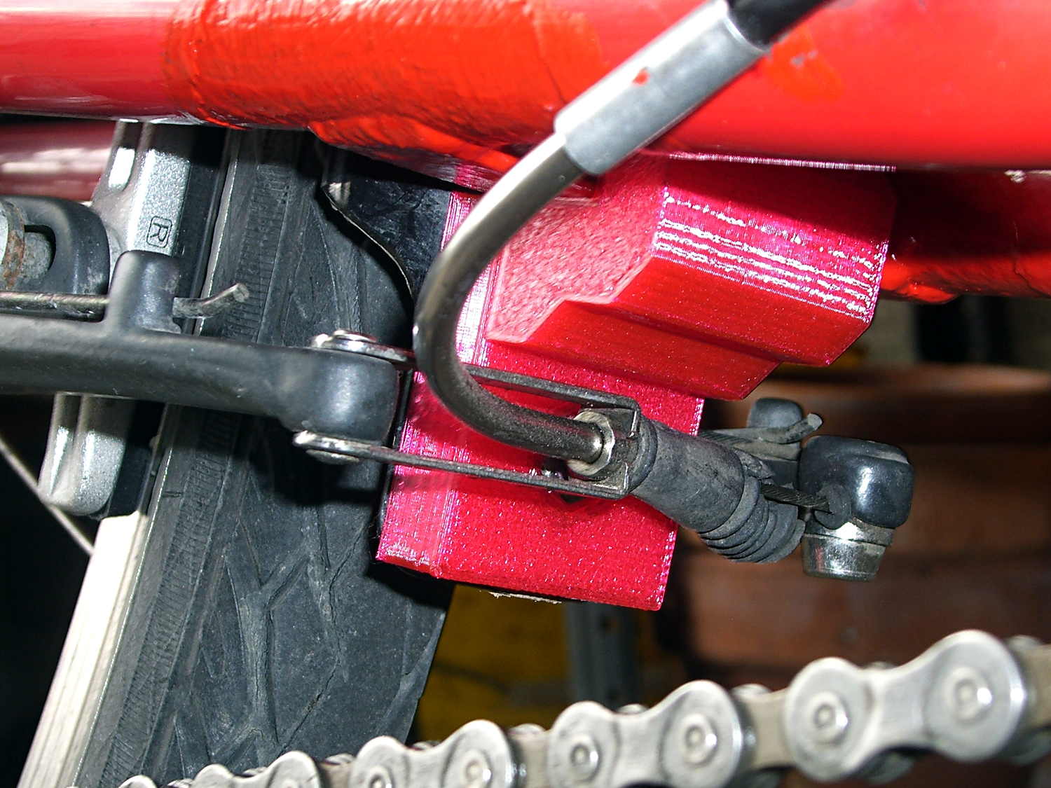
From below, you can see why the top block can’t extend all the way to the bottom of the fender mount:
That rubber boot needs replacing in the worst possible way, but I didn’t have anything suitable on hand and wouldn’t dismount that cable even if I had; cables never go back on properly.
Alas, because the brakes weren’t mounted when I did the measurements, I had to build one to find out why a long block wouldn’t work:

The screw atop the block (on the left in that picture) presses a small plastic slug against the steel strap, in the hopes it won’t chew through the paint quite as rapidly. The screws & nuts are stainless, so at least they’ll survive for a while.
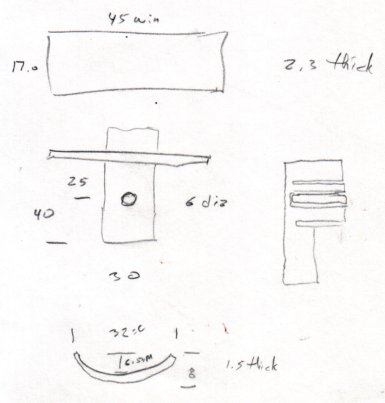
The curve in the trough comes from the chord equation applied to these crude measurements:
Fortunately, it’s tucked into a spot where nobody ever looks…
The OpenSCAD source code:
// Tour Easy rear fender bracket
// Ed Nisley KE4ZNU March 2015

Layout = "Build";		// Build Show TabHolder Block

//- Extrusion parameters must match reality!

ThreadThick = 0.25;
ThreadWidth = 0.40;

HoleWindage = 0.2;

Protrusion = 0.1;			// make holes end cleanly

inch = 25.4;

function IntegerMultiple(Size,Unit) = Unit * ceil(Size / Unit);

//----------------------
// Dimensions

PlateWidth = 45;		// Tour Easy frame plate
PlateDepth = 17;
PlateThick = 3.3;		//  ... allow for a bit of crud

TabWidth = 32;			// fender tab
TabLength = 40;
TabThick = 1.5;
TabDepth = 8;

ChordM = TabDepth - TabThick;	// find fender tab's radius of curvature
ChordC = TabWidth;

TabRadius = ((ChordM * ChordM) + (ChordC * ChordC)/4) / (2 * ChordM);
echo(str("Fender radius: ", TabRadius));

FenderOffset = -25.0;		// from bottom of frame plate

ScrewClear = 5.0;			// close enough to 10-32
ScrewTap = ScrewClear - 1.0;

NutThick = 3.1;				// 10-32 nut
NutOD = 9.5;				//  ... across flats

Chamfer = 5.0;					// edge chamfer

BlockSlab = 10.0;
BlockWidth = TabWidth;
BlockDepth = PlateDepth + BlockSlab;
BlockHeight = TabLength + PlateThick + BlockSlab;

BlockOutline = [
	[TabDepth/2,0],
	[TabDepth/2,TabLength],
	[PlateDepth,TabLength],
	[PlateDepth,TabLength + PlateThick],
	[0,TabLength + PlateThick],
	[0,BlockHeight - Chamfer],
	[Chamfer,BlockHeight],
	[BlockDepth - Chamfer,BlockHeight],
	[BlockDepth,BlockHeight - Chamfer],
	[BlockDepth,TabLength - BlockSlab + Chamfer],
	[BlockDepth - Chamfer,TabLength - BlockSlab],
	[BlockSlab + Chamfer,TabLength - BlockSlab],
	[BlockSlab,TabLength - BlockSlab - Chamfer],
//	[BlockSlab,Chamfer],								// full-length tab (TrimBlock = false)
//	[BlockSlab - Chamfer,0],							//   ""
	[TabDepth/2,TabLength - BlockSlab - Chamfer]		// trim lower tab (TrimBlock = true)
	];

TrimBlock = true;

BuildGap = 5.0;

//----------------------
// Useful routines

module PolyCyl(Dia,Height,ForceSides=0) {			// based on nophead's polyholes

  Sides = (ForceSides != 0) ? ForceSides : (ceil(Dia) + 2);

  FixDia = Dia / cos(180/Sides);

  cylinder(r=(FixDia + HoleWindage)/2,
           h=Height,
	   $fn=Sides);
}

//- Locating pin hole with glue recess
//  Default length is two pin diameters on each side of the split

PinOD = 1.75;
PinOC = TabLength / 2;

module LocatingPin(Dia=PinOD,Len=0.0) {

	PinLen = (Len != 0.0) ? Len : (4*Dia);

	translate([0,0,-ThreadThick])
		PolyCyl((Dia + 2*ThreadWidth),2*ThreadThick,4);

	translate([0,0,-2*ThreadThick])
		PolyCyl((Dia + 1*ThreadWidth),4*ThreadThick,4);

	translate([0,0,-(Len/2 + ThreadThick)])
		PolyCyl(Dia,(Len + 2*ThreadThick),4);

}

module LocatingPins(Length) {
	for (i=[-1,1])
	translate([i*PinOC/2,0,0])
		rotate(180/4)
		LocatingPin(Len=Length);
}

//----------------------
// Pieces

module TabHolder() {

	difference() {
		translate([-TabWidth/2,-TabLength,0])
			cube([TabWidth,TabLength,2*TabDepth],center=false);

		translate([0,-TabLength/4,0])
			LocatingPins(5.0);

if (!TrimBlock)
		translate([0,-3*TabLength/4,0])
			LocatingPins(5.0);

		translate([0,FenderOffset,-Protrusion])
			rotate(180/6)
				PolyCyl(ScrewClear,3*TabDepth,6);

if (TrimBlock)
		translate([0,FenderOffset,-Protrusion])
			rotate(180/6)
				PolyCyl(NutOD,NutThick + Protrusion,6);

		translate([0,TabLength,TabRadius + TabDepth/2])
			rotate([90,0,0])
				rotate(180/(6*4))
					cylinder(r=TabRadius,h=3*TabLength,$fn=6*4);
	}

if (TrimBlock)
	color("Yellow")
	translate([0,FenderOffset,0])
		for (Seg=[0:5]) {
			rotate(30 + 360*Seg/6)
			cube([NutOD/2,
				2*ThreadWidth,
				(NutThick - ThreadThick)],center=false);
		}

}

module Block() {

	difference() {
		linear_extrude(height=BlockWidth,convexity=3)
			polygon(points=BlockOutline);

if (!TrimBlock)
		translate([TabDepth/2,TabLength/4,BlockWidth/2])
			rotate([0,90,0])
				LocatingPins(5.0);

		translate([TabDepth/2,3*TabLength/4,BlockWidth/2])
			rotate([0,90,0])
				LocatingPins(5.0);

		translate([-BlockDepth,TabLength + FenderOffset,BlockWidth/2])
			rotate([0,90,0])
				rotate(180/6)
					PolyCyl(ScrewClear,3*BlockDepth,6);

		translate([PlateDepth/2,BlockHeight - BlockSlab - Protrusion,BlockWidth/2])
			rotate([-90,0,0])
					PolyCyl(ScrewTap,2*BlockSlab,6);

if (!TrimBlock)
		translate([(BlockSlab - NutThick),(TabLength + FenderOffset),BlockWidth/2])
			rotate([0,90,0])
				rotate(180/6)
					PolyCyl(NutOD,NutThick + Protrusion,6);

	}

}

//----------------------
// Build it

if (Layout == "TabHolder")
	TabHolder();

if (Layout == "Block")
	Block();

if (Layout == "Show") {
	translate([0,BlockWidth/2,0])
		rotate([90,0,0]) {
			color("Magenta")
				Block();
			color("Orange")
				translate([0,TabLength,TabWidth/2])
					rotate([0,-90,0])
						TabHolder();
		}
}

if (Layout == "Build") {

	translate([-BuildGap,0,0])
		rotate(-90)
			TabHolder();

	translate([BuildGap,TrimBlock ? -BlockHeight/1.5 : -BlockHeight/3,0])
		Block();
}

Comments
3 responses to “Tour Easy Rear Fender Bracket”
Unlike with machining, working with 3D printers makes you think about the “grain” of stuff, and orienting parts for best performance, like working with wood. You also have to worry about overhangs and so forth.
You didn’t think you liked that magenta PETG, but you’re right, it does look good with the red ‘bent.
And the “chewing through the pain” typo made me grin.
This one may become an adhesive testcase, too. The IPS 4 I’ve been using works great on PLA and reasonably well on PETG, but a series of PETG parts with small mating surfaces didn’t fuse at all. If the fender starts flopping around after a few hundred miles, I’ll know IPS 4 isn’t nearly as good as I thought for PETG.
[…] think that calls for a nice 3D printed bracket, too, but the snippet got me back on the bike faster. When I preemptively replace the fork on […]