Ed Nisley's Blog: Shop notes, electronics, firmware, machinery, 3D printing, laser cuttery, and curiosities. Contents: 100% human thinking, 0% AI slop.
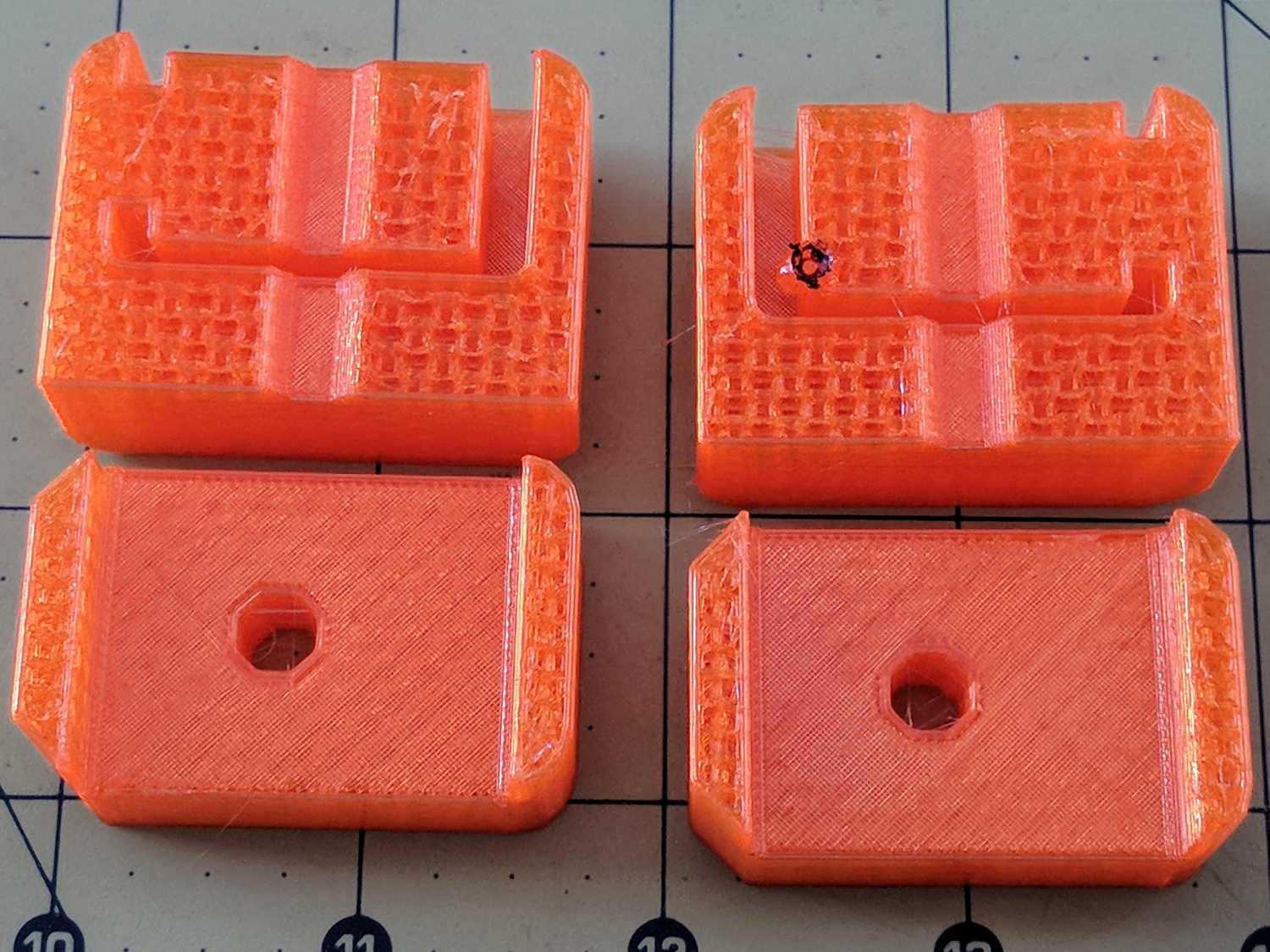
The neighborhood raccoons made off with our steel-cage suet feeder, leaving a dangling chain, several puzzled woodpeckers, and a potential gap in Mary’s FeederWatch data. A quick Thingiverse search turned up a likely candidate and a few hours of 3D printing produced a replacement:
3D printed suet feeder
The cheerful party colors just sort of happened after I realized orange wasn’t the new steel.
I bandsawed the top plate from an acrylic sheet, rather than devote several hours to printing a simple disk with two slots. Said slots came from a bit of freehand work with the drill press, a step drill bit, and a nasty carbide milling bur(r).
The loops holding the chains won’t last for long, as hairy and red-bellied woodpeckers land with thump.
It hangs from the stub of a former ski pole, loosely secured to the bracket holding the former feeder, and extending another two feet over the abyss beyond the patio. I doubt the raccoons will remain daunted for long, but maybe they’ll catch a heart attack when it collapses.
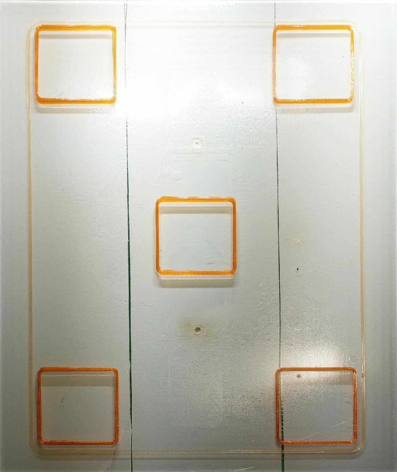
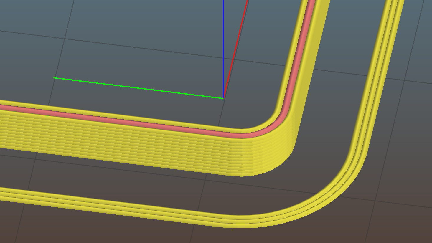
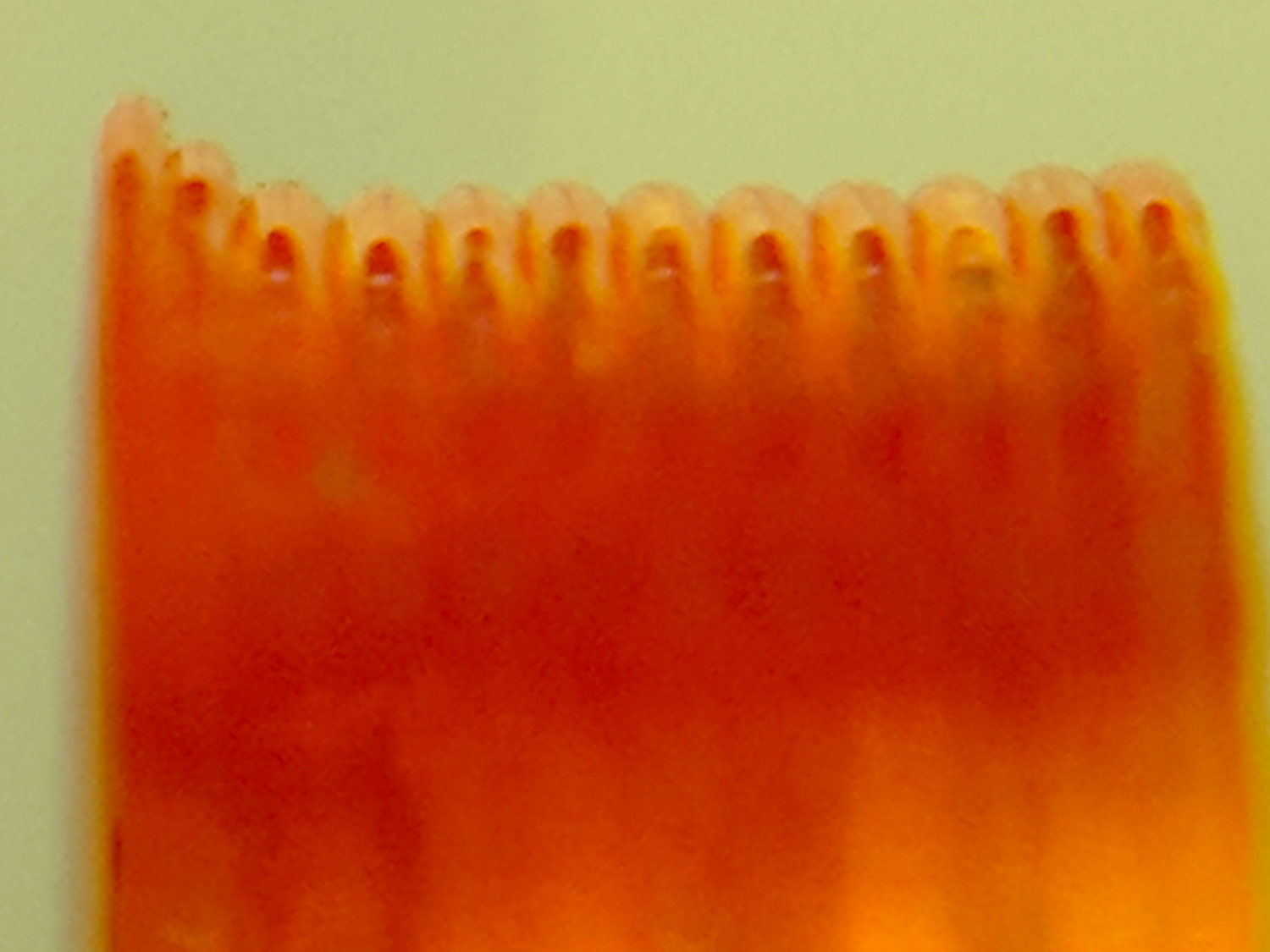
The skirt is scant at 0.20 mm, the boxes are 0.15 mm short at 2.85 mm, and the walls are 0.03 mm too thin. Some Z offset adjustment seems in order, as the first few layers (on the left) came out grossly squished:
Calibration box – 2.85 – detail
However, the box heights came out sufficiently uniform to show the platform alignment remains just fine.
Putting it there replaces all the mechanical putzing and adjusting cute little screws / bolts / nuts / spacers / suchlike with a simple offset in the startup G-Code:
G28 Z-2.15 ; home Z to platform switch, with measured offset
So I changed the startup G-Code in Slic3r to use G28 Z-2.30, sliced a single box in the middle of the platform, printed it, and … it came out exactly the same height: 2.85 mm.
Huh.
To make a very long story short, it turns out Marlin 1.1 ignores the numeric parameter in G28. When I updated the firmware to that version, I had changed the Configuration.h file to include the homing offsets:
So, with the same offset burned into the firmware, it looked like the startup G-Code was Doing The Right Thing. I never deleted the offset from the startup G-Code and, at some point, Marlin stopped supporting the numeric parameter.
Huh.
However, the X and Y homing offsets must be hardcoded, because I want the XY origin in the middle of the platform to match my original OpenSCAD part designs. Everybody else prefers the XY origin in the front-left corner. FWIW, in Marlin 1.1-RC5 (two years old by now), the #define BED_CENTER_AT_0_0 constant appears only in that line and nowhere else in the source code. Maybe it was a change in progress back then?
Anyhow, rather than hardcode the Z offset again, I set it to 0.00:
Recompile and reload the firmware, then change the startup G-Code to use G28 Z without the offset.
Doing so means I can measure and adjust the actual Z offset with M206, then store the value in EEPROM with M500:
M206 Z-2.25
M500
I went a little short at -2.25, for reasons I cannot explain now.
Measuring the offset goes like this:
Zero the offset: M206 Z0
Move the extruder off to the right: G0 X135
Home Z: G28 Z
Get some air under the nozzle: G0 Z4.0
Measure the actual clearance, perhaps using your taper gauge, at (let’s say) 1.7 mm
Set (1.7 – 4.0) as the offset: M206 Z-2.3
Print a box and adjust the offset accordingly
Using my actual measurement, not the for-instance example, I resliced the box, printed it, and it came out at 2.94 mm, just slightly short, so I re-tweaked the offset to Z-3.28 and re-stored it.
Embiggening the wall thickness turned out to be a matter of updating the filament diameter. I measured the start of the current spool of orange PETG at 1.75 mm, the same as the previous natural PETG spool, but the current section is 1.70 mm. Plugging that into Slic3r, reslicing, and reprinting produced a dead-on square: 3.00 mm tall with 1.20 mm walls:
Calibration Square series
The skirt now comes out at 0.25 mm, the way it should, too. The difference between the original 0.20 mm skirt and 0.25 mm suggests the squashed center thread (of the three in the skirt around the first set of five boxes) forced the two adjacent threads to become a bit taller, for lack of somewhere for the excess plastic to go on one side of each thread, and the nozzle rode higher than you’d (well, I’d) expect from the bare numbers.
The picture is missing a few squares in the middle, because I couldn’t believe changing the G28 Z-2.15 offset had no effect. It was easier to believe I’d inadvertently loaded the wrong file than the software / firmware was doing something wrong.
However, during the course of the adventure, I established M851 does exactly nothing in this context, perhaps because it applies to some different type of homing / probing / mesh leveling / whatever. You can set the Z offset with several other G-Code and M-Code commands, but the documentation isn’t always forthcoming about how the various methods interact and different firmware uses identical codes for completely different functions, so proceed with Exceedingly Great Caution.
In any event, it’s much easier and faster to adjust the printer & slicing parameters by measuring test boxes than by puzzling over actual prints, so …
This file contains hidden or bidirectional Unicode text that may be interpreted or compiled differently than what appears below. To review, open the file in an editor that reveals hidden Unicode characters.
Learn more about bidirectional Unicode characters
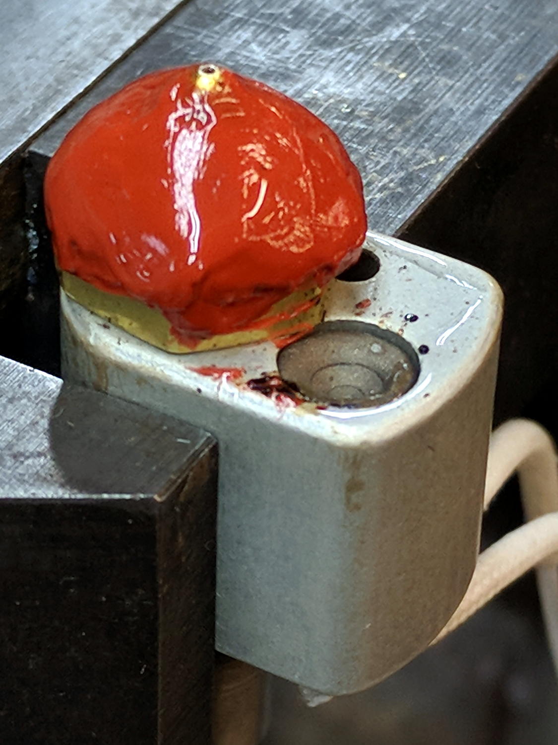
Quite some time ago, Vedran described a silicone boot he put over the nozzle. Rather than building a mold and casting the RTV, I threw caution to the winds, ignored any acetic acid corrosion issues, and troweled a layer of RTV on the nozzle:
M2 – nozzle silicone – applied
That’s JB Weld Hi-Temp Red Silicone, rated up to 550 °F = 290 °C continuous operation, so it should be Just Fine at PETG’s usual 250 °C.
I slipped the rebuilt thermistor into its hole, slipped the hot end back into the M2’s extruder, raised it a bit higher than it was before, fired up the M2, and …
Home the X axis
Set X offset: G28 X-100
Move it off to the right: G0 X130
Home the Z axis
Set Z offset: G28 Z-2.15
The Y axis is pretty near the middle, so it’s all good
Move the nozzle to the middle: G0 X0
Move the platform to Z=0: G0 Z0
N.B.: I have the XY=0 origin in the middle of the platform, so don’t do like I do and expect it to work if you put the origin elsewhere.
Then loosen the hot end clamp, slide the hot end down until the nozzle touches the platform, tighten the clamp, and the tip of the nozzle should be pretty close to where it started out:
M2 – nozzle silicone – Z 0.0 set
The microswitch in the background senses the top of the platform, eliminating all the putzing around everybody else does to get a consistent Z offset. I verified the switch trip point by sliding my trusty Starrett No. 270 Taper Gage under the lever until it tripped at 2.1 mm; about as close to 2.15 mm as one might hope for.
The PETG hairs I described in the original post were conspicuous by their absence. It’s too early to tell if the silicone coating is a complete cure, but at least it’s not causing any obvious problems.
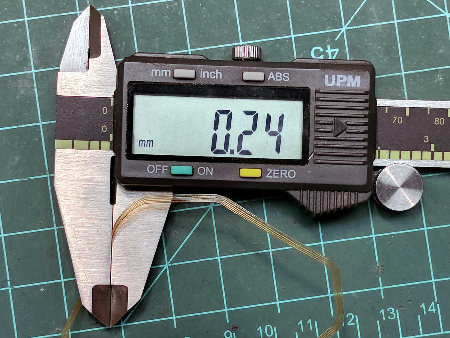
The skirt around those parts came out close enough to its nominal 0.25 mm layer thickness:
M2 – nozzle alignment – skirt thickness
I must print some calibration squares to verify the platform alignment and the overall height.
Just for completeness, here’s looking up at the new nozzle, snug inside its fuzzy fiberglas insulating wrap, with a PETG strand drooling from its orifice:
M2 – nozzle silicone – bottom view
I really should order a couple of thermistors, a cartridge heater, and maybe a nozzle …
The MAXTEMP error killing the M2 while printing the bar clamp mounts (probably) came from a short in the thermistor pellet that lowered the thermistor resistance and raised the calculated temperature. I manually heated the extruder and, although the temperature stabilized at 250 °C, the history plot showed irregular downward jogs from increasing resistance. Whenever this constellation of symptoms appears on the M2 forums, I always recommend ordering another thermistor or two, so …
Start by turning a 1/8 inch OD brass tube down to 3.00 mm, parting off a suitable length, facing the ends:
M2 – thermistor brass tube turning
Countersink the ends just for pretty.
The tube should be a slip fit in the hot end:
M2 – hot end thermistor – turned brass tube
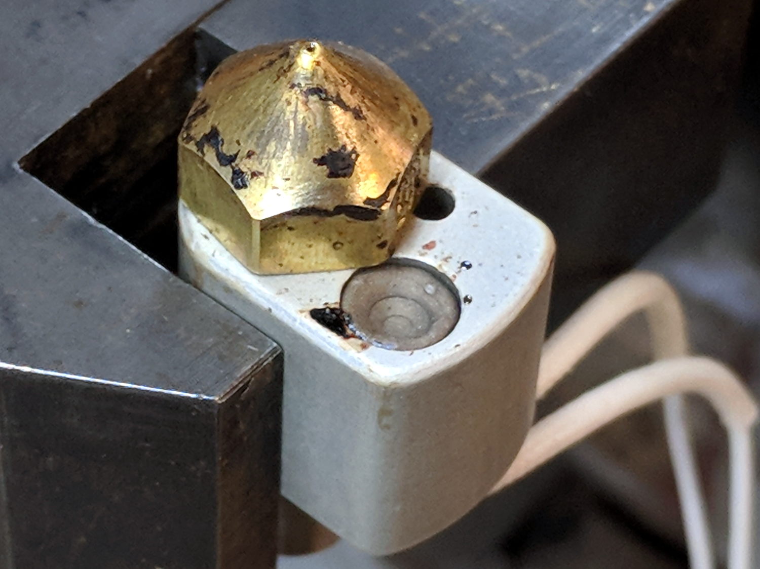
While I had the hot end on the bench, I scuffed the nozzle to remove (most of) the baked-on crud:
M2 – nozzle silicone – cleaned nozzle
The plan is to seal the thermistor bead inside the tube with JB Weld epoxy, which I’ve verified (!) to work at extrusion temperatures, depending on the epoxy to insulate the wiring and immobilize all the pieces.
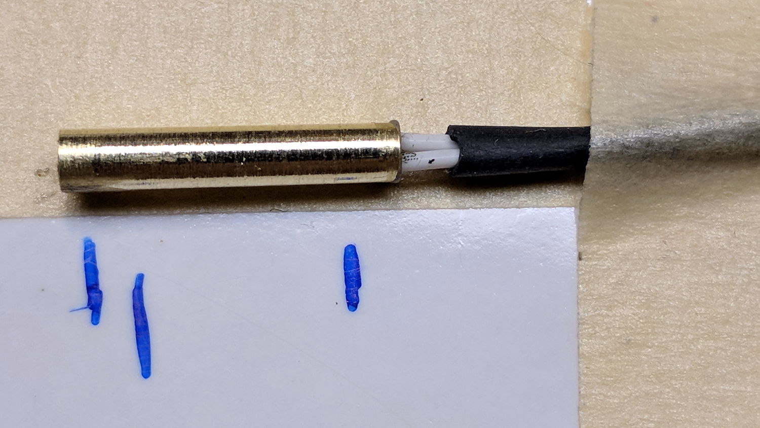
Harvest the original wire harness from the defunct thermistor, solder to the bead, lay out guide lines:
M2 – thermistor – assembly 1 layout
Slobber epoxy over everytyhing, fill the tube, insert bead into tube, stabilize with tape:
M2 – thermistor – assembly 1 curing
Verify connectivity through the thermistor and isolation from the brass tube, then return upstairs to warm up thaw out while the epoxy cures.
At this point, the observant reader should be thinking “Uh, Ed, that bead looked a tad large. Are you absolutely sure … ?”
Halfway up the basement stairs I realized I’d meticulously entombed a 10 kΩ thermistor, not the 100 kΩ thermistor used in the M2’s hot end. You can easily verify the resistance, as I did, with a quick web search; I have hella-good SEO for some specific topics.
Back to the lab …
Fortunately, JB Weld has a pot life over an hour, so extract the wrong bead, unsolder, install the right thermistor using snippets of insulation harvested from the original wiring, realign components:
M2 – thermistor – assembly 2 layout
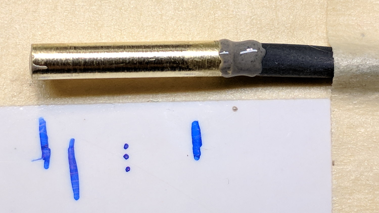
Reapply epoxy:
M2 – thermistor – assembly 2
Re-verify resistances, return upstairs, fast-forward through the night, have another good idea …
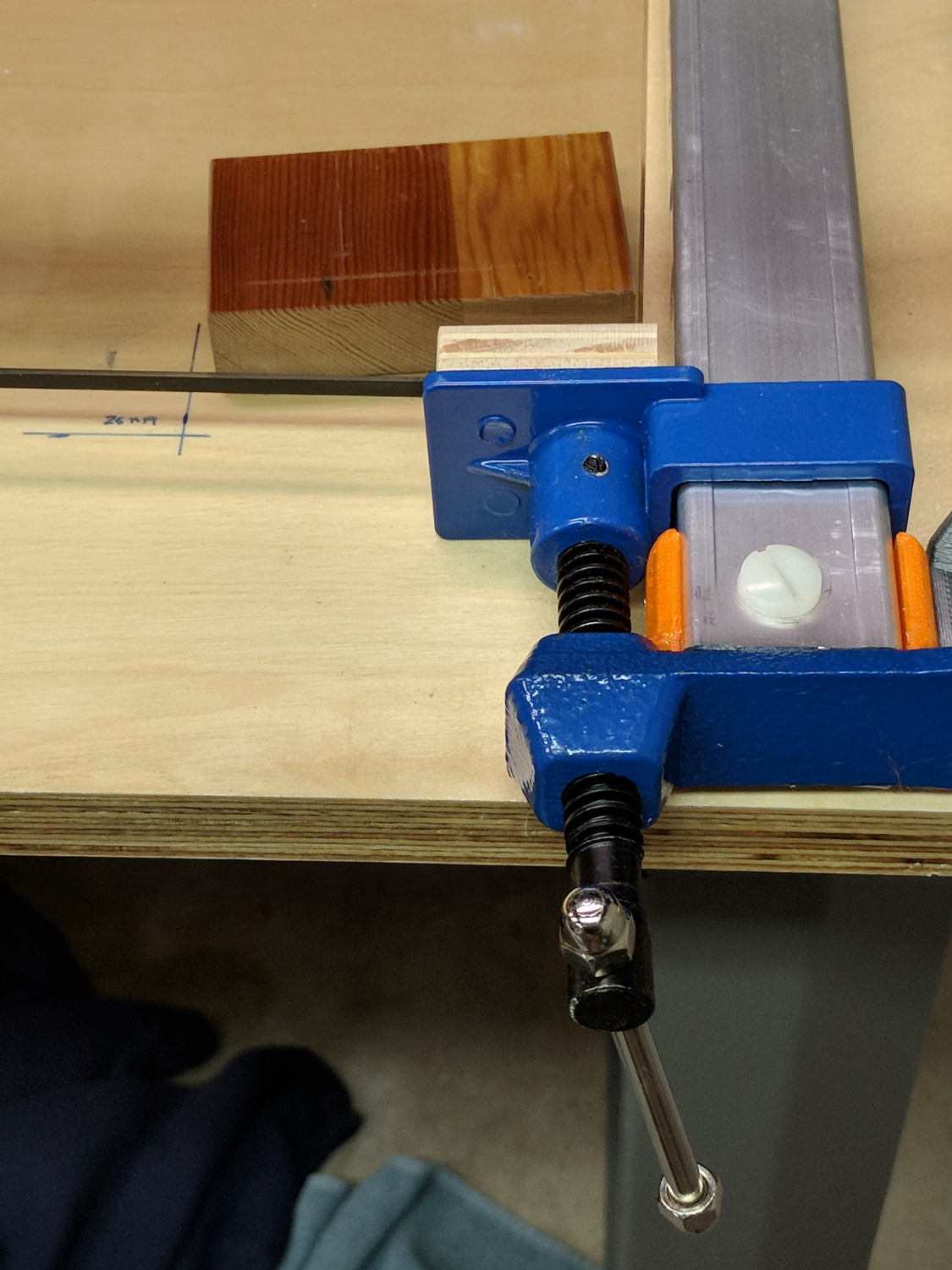
Using various prototypes of the bar clamp mounts, here’s the left-side clamp in action:
MPCNC – bar clamp trial installation
In round numbers, the (yet to be installed) spindle won’t exert any upward force worth mentioning, so clamping the material in the horizontal plane should hold it firmly enough for my simple needs. A more robust router needs more downward force.
The left-side clamp sits outside the MPCNC’s frame to prevent blocking the leftmost inch or so of the work area:
MPCNC – bar clamp left
Although the right-side clamp is inside the frame rails, the gantry’s asymmetry puts the clamp outside of the work area:
MPCNC – bar clamp right
Yes, those are nylon bolts; my 1/4-20 bolt stash is greatly depleted. I picked up a small assortment of stainless bolts in useful sizes, but they top out at 1-½ inch.
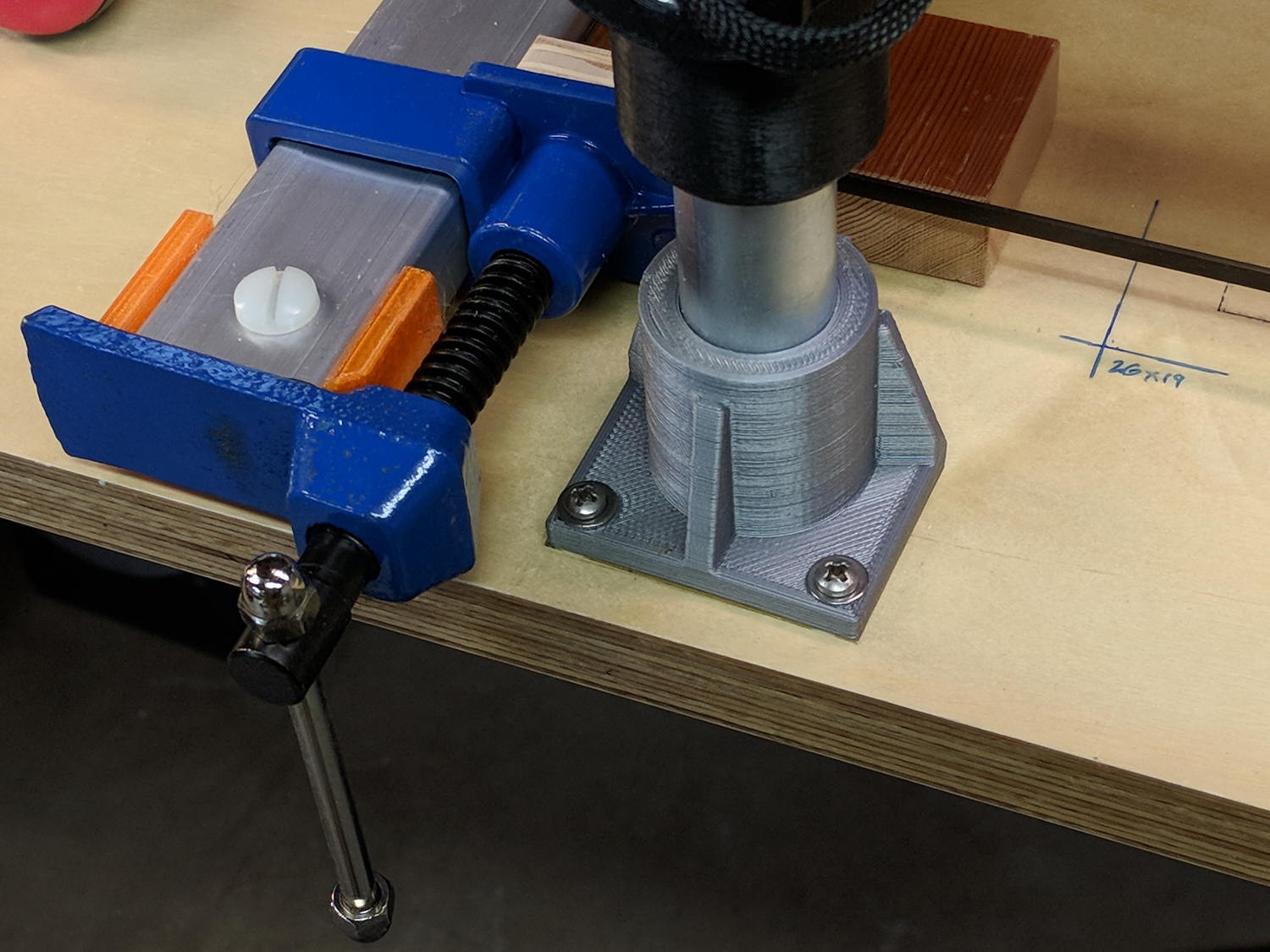
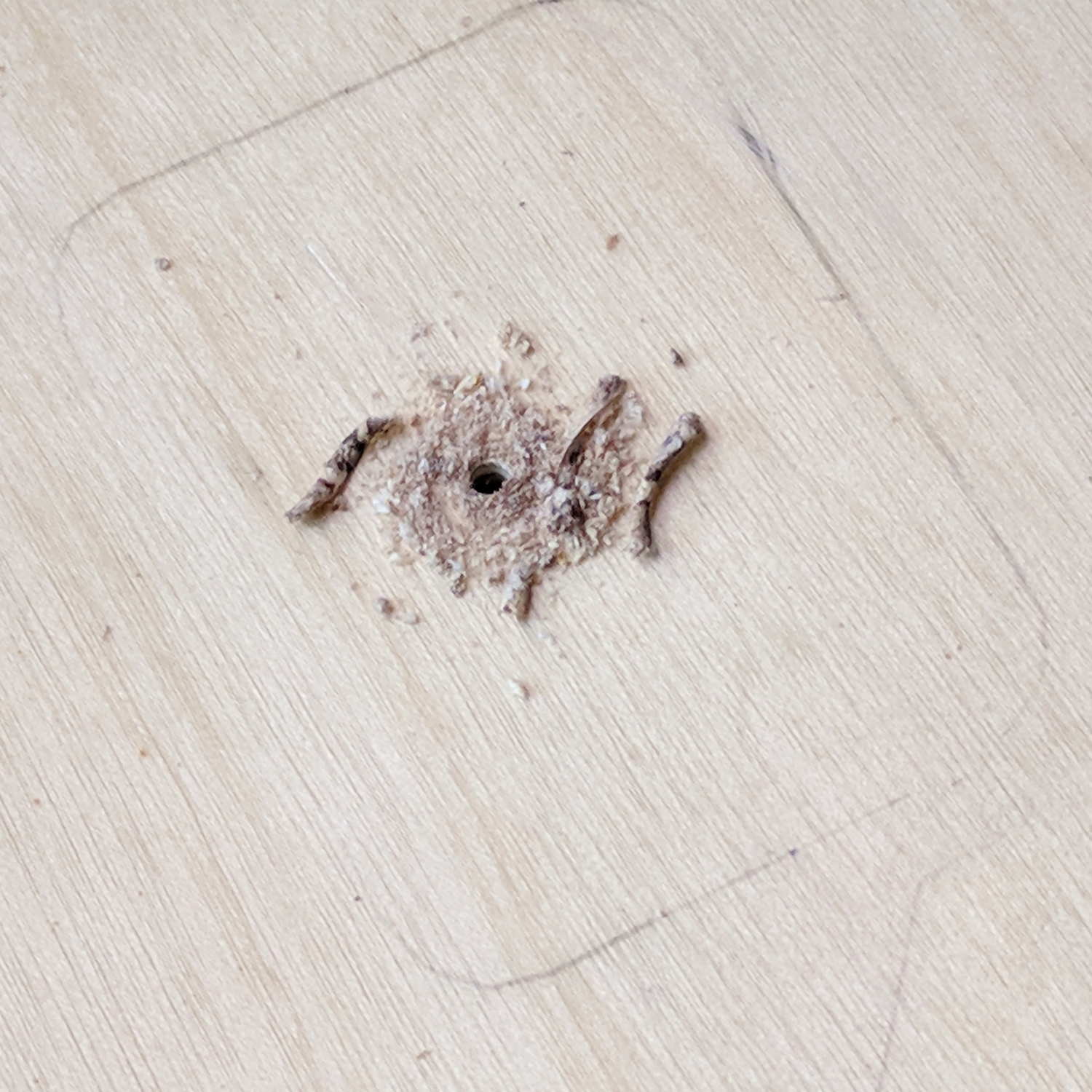
Fastening the blocks to the bench required a bit of fiddling after squaring the bars against the edge. Transfer-punch the hole location, then drill a 1/16 inch pilot hole:
Gingerly counterbore a t-nut recess in the bottom with a 3/4 inch Forstner bit marked with a suitable depth to completely sink the t-nut:
MPCNC – t-nut counterbore
The shop vac snout keeps the chips out of your face. Works like a champ!
Redrill the pilot hole with a 5/16 inch brad-point bit to fit the 1/4-20 t-nut body:
MPCNC – t-nut in counterbore
The t-nut may not be exactly centered in the counterbore, but nobody will ever notice.
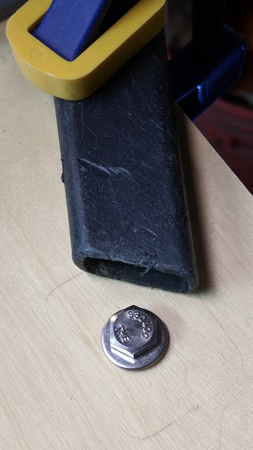
Rather than hammering the t-nut into the bench, gently & quietly pull it in place with a bolt atop a pair of washers:
MPCNC – bolt for t-nut installation
Again, the shop vac collected all the chips from the brad-point bit.
Of course, Harbor Freight bar clamps aren’t intended for this duty, so they’re held together with assemble-only pins and clips. Disassemble the clip with a Dremel cutoff wheel and the pin will fall right out:
Bar Clamp – pin removal
I had to through-drill the bar + hardware + 3D printed mount to get a consistent hole, as the overall tolerances aren’t particularly tight and things tend to not fit back together the way they came apart.
The bar clamps started out at 36 inches and stuck out over the far end of the bench. I hacksawed them to a suitable length, cleaned up the cut on the bandsaw, and the cut disappears in the end block:
MPCNC – bar clamp end block
By complete coincidence, the rear bolt holes turned out to be exactly lined up with the edge of the metal bench frame, so I had to remove eleven of the twelve screws holding the bench to the frame, rotate it slightly, drill the rear holes, install the t-nuts, un-rotate the top, and reinstall all the screws. As it turns out, the four end screws are located in blind parts of the frame where I could remove three of them, but cannot re-install them with any tool at my command. I think I can conjure a modified finger wrench, but …
The bars are made of the softest aluminum known to man in the thinnest cross-section that won’t crumple under a stiff glance, so they’re more flexy than you’d (well, I’d) like. Various comments suggest running a snug-fitting strip of 3/4 inch plywood inside the rail to stiffen it up; we’ll see how they fare against the MPCNC’s actual cutting forces before doing anything rash.
The jaws are also way slicker than I’d like and may need screwed- or glued-on plywood pads for better grip.
Those are all early versions of the mounting blocks, because this happened while printing the final set:
MPCNC – failed bar clamp mounts
The black smudge on the block in the upper right is what happens when a MAXTEMP error shuts the printer down in mid-stride, leaving the nozzle to cool in the part. Looks like it’s time for a new thermistor …
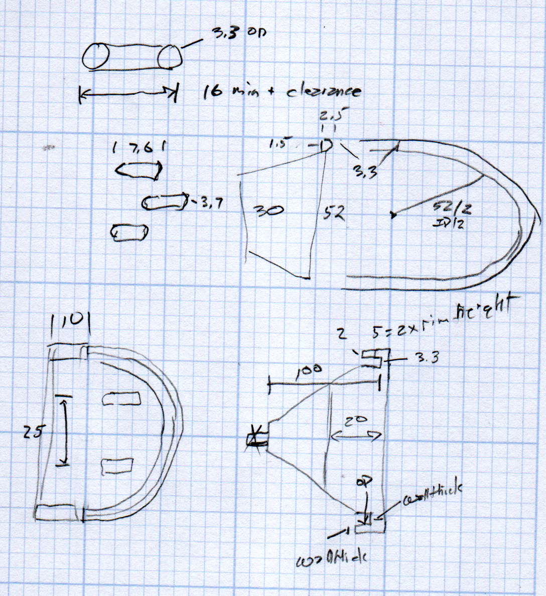
We just scrapped out the old dish drainer, only to find the gadget bin on the new drainer let the measuring spoons fall over and lie along its bottom. After a week of fishing them out from under paring knives, cheese slicers, and suchlike, I gimmicked up a holder:
Measuring Spoon Drainer – installed
One might suggest natural PETG, rather than orange, thereby displaying a shocking ignorance of the MVP concept. We’ll run with orange for the shakedown trials, then build-measure-learn, iterate, and, for all I know, we may even pivot.
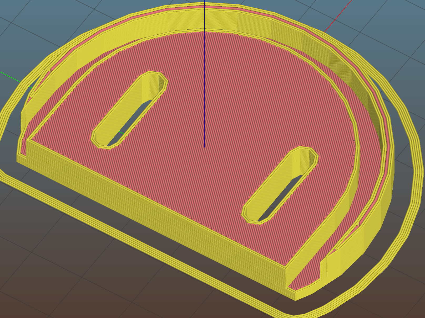
A bottom-up view of the solid model shows the trench accommodating the bin lip:
This file contains hidden or bidirectional Unicode text that may be interpreted or compiled differently than what appears below. To review, open the file in an editor that reveals hidden Unicode characters.
Learn more about bidirectional Unicode characters
The MPCNC uses a DW660 Cutout tool as a low-cost spindle for tools with 1/8 and 1/4 inch shanks. It features a tool-free “collet grip” to twist the collet nut against the shaft lock, which is convenient for a hand tool and not so much for a CNC spindle: I find it difficult to get two hands into the MPCNC setup with the proper orientation to push-and-hold two locking buttons, while applying enough torque to twist the collet nut:
DW660 – collet grip
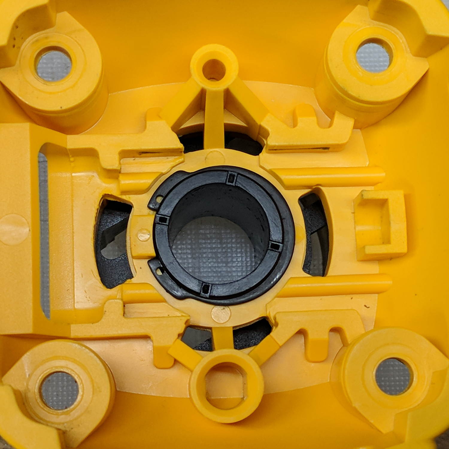
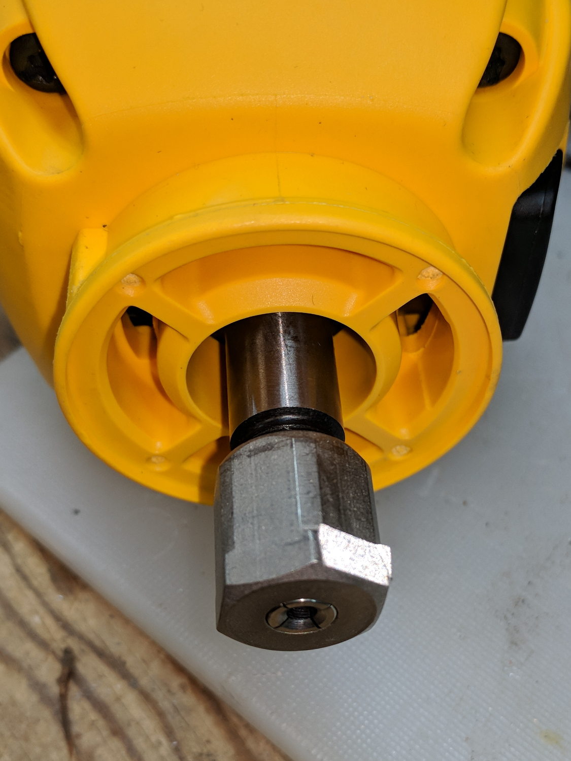
Fortunately, it’s easy enough to remove the collet grip. Remove the collet nut, unscrew the four screws holding the yellow snout in place, then pull the snout straight off to reveal the spindle lock plate:
DW660 – nose cap interior
Capture the spring, slide the spindle lock plate out to expose the snap ring (a.k.a. Jesus clip) holding the collet grip in place:
DW660 – collet grip snap ring
Remove the snap ring, make the appropriate remark, pull the collet grip out of the snout, reassemble the snout in its One Correct Orientation, and you’re done:
DW660 – collet grip removed
The retroreflective tape snippet let my laser tachometer report a top speed over 29 k rpm, pretty close to the advertised 30 k rpm.
If one were fussy, one would 3D print a thing to cover the snout’s open end:
DW660 – snout cover
The original snap ring holds it in place and the fancy pattern comes from octogram spiral infill on the bottom.
The collet nut fits either a 5/8 inch or 16 mm wrench, both of which stick out to the side far enough for a convenient hold while pressing the shaft lock button.