Rather than attach a spoil board directly to the bench top under the MPCNC, one can grab it in bar clamps anchored to the bench, which requires suitable mounts. Because bar clamps are all the same, one must be flipped over to point the other way, soooo the mounts come in mirror-image sets.
Holding the clamp on the left side of the table:
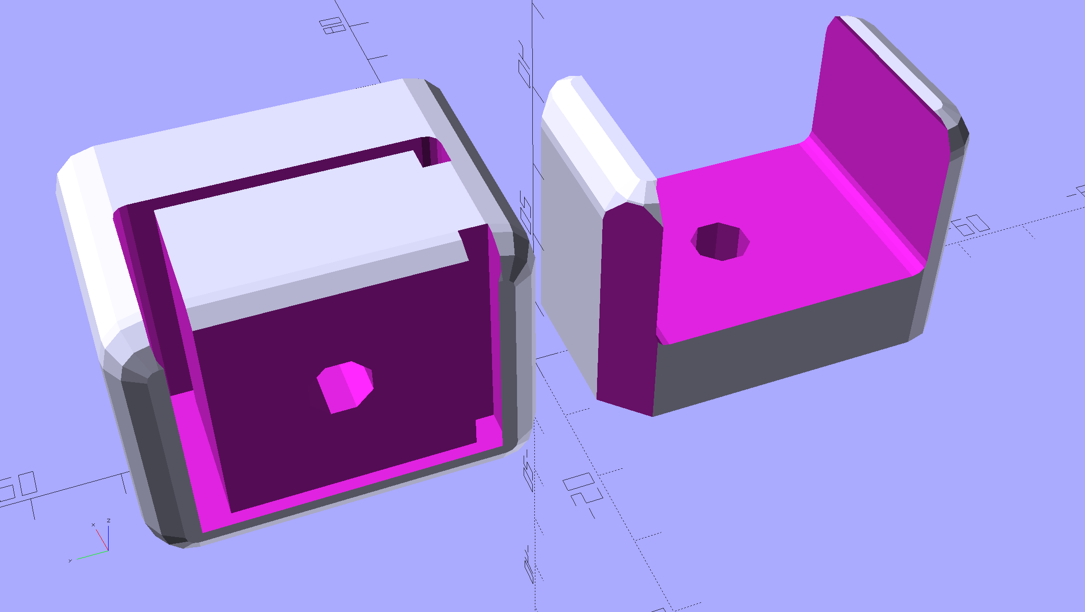
For the right-side clamp:
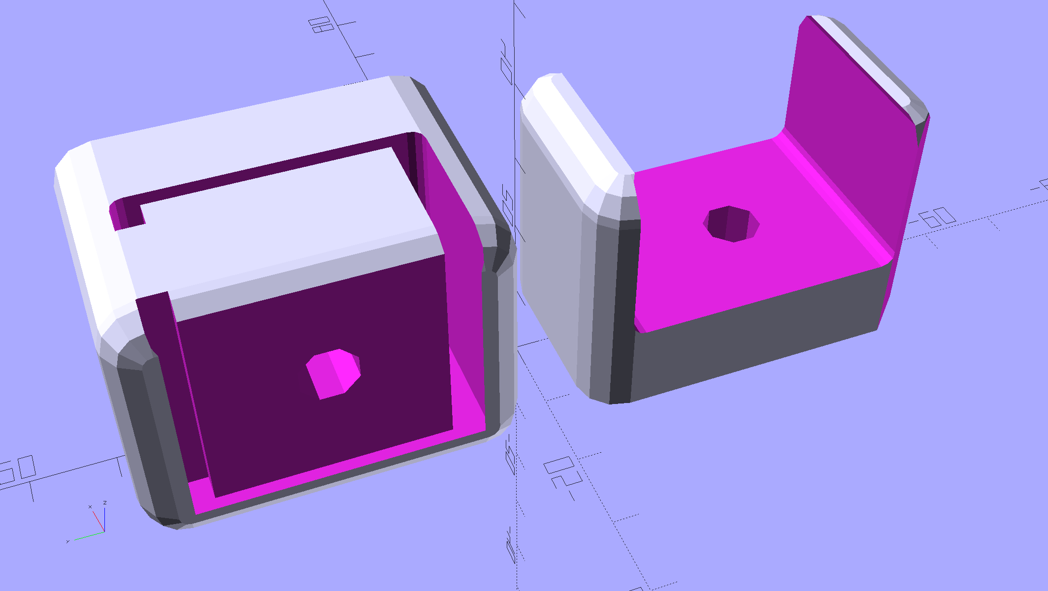
The chunky clamp prints on its end, with its bottom surface facing away from you, to let the block in the middle print without support. In that orientation, the bar slides in from the top.
The fancy rounded corners happened while I iterated on getting the dimensions right.
Actually printing and installing the things turned out to be separate challenges.
The OpenSCAD source code as a GitHub Gist:
| // MPCNC Bar Clamp Mounts | |
| // Ed Nisley KE4ZNU – 2018-02-03 | |
| Layout = "Build"; // BarEnd EndBlock ScrewBlock Build | |
| Chirality = "Right"; // bar handedness = side with opening | |
| /* [Extrusion] */ | |
| ThreadThick = 0.25; // [0.20, 0.25] | |
| ThreadWidth = 0.40; // [0.40] | |
| /* [Hidden] */ | |
| Protrusion = 0.1; // [0.01, 0.1] | |
| HoleWindage = 0.2; | |
| function IntegerMultiple(Size,Unit) = Unit * ceil(Size / Unit); | |
| ID = 0; | |
| OD = 1; | |
| LENGTH = 2; | |
| //- Adjust hole diameter to make the size come out right | |
| module PolyCyl(Dia,Height,ForceSides=0) { // based on nophead's polyholes | |
| Sides = (ForceSides != 0) ? ForceSides : (ceil(Dia) + 2); | |
| FixDia = Dia / cos(180/Sides); | |
| cylinder(r=(FixDia + HoleWindage)/2,h=Height,$fn=Sides); | |
| } | |
| /* [Clamp] */ | |
| BarEndOut = [34.5,21.0]; // outside dimensions | |
| BarEndIn = [28.0,18.0]; // … inside | |
| BarEndSlot = [2.8,11.5]; // slot on open side | |
| BarEndRadius = 1.5; // corner rounding | |
| NumSides = 3*4; // … and sides | |
| BarHeightOC = 22.0; // min height above bench | |
| Clearance = 0.2; // overall bar clearance | |
| PinOffset = [14.0,2.5]; // clamp hardware pin location | |
| PinOD = 6.5; // … pin OD | |
| WallThick = 5.0; // basic wall & floor thickness | |
| EndBlockSize = [2*PinOffset.x + WallThick,BarEndOut.x + 2*WallThick,BarHeightOC + BarEndOut.y/2]; | |
| ScrewBlockSize = [2*PinOffset.x,BarEndOut.x + 2*WallThick,BarHeightOC + BarEndOut.y/2]; | |
| //—– | |
| // Define shapes | |
| // Aluminum bar extrusion | |
| module BarEnd(Length = 2.0,Hollow=true) { | |
| linear_extrude(height=Length,convexity=3) | |
| offset(delta=Clearance) | |
| difference() { | |
| hull() | |
| for (i=[-1,1], j=[-1,1]) | |
| translate([i*(BarEndOut.x/2 – BarEndRadius),j*(BarEndOut.y/2 – BarEndRadius)]) | |
| circle(r=BarEndRadius,$fn=3*4); // not related to block corner rounding | |
| if (Hollow) { | |
| translate([BarEndOut.x/2 – BarEndIn.x/2 – BarEndSlot.x,0]) | |
| square(BarEndIn,center=true); | |
| translate([BarEndOut.x/2,0]) | |
| square([BarEndOut.x,BarEndSlot.y],center=true); | |
| } | |
| } | |
| } | |
| // Block supporting open end of Bar | |
| module EndBlock() { | |
| Normal = (Chirality == "Left") ? [0,0,0] : [0,1,0]; | |
| Radius = WallThick; | |
| mirror(Normal) | |
| difference() { | |
| if (true) | |
| hull() { | |
| dx = EndBlockSize.x/2 – Radius; | |
| dy = EndBlockSize.y/2 – Radius; | |
| for (i=[-1,1],j=[-1,1]) | |
| translate([i*dx,j*dy,EndBlockSize.z – Radius]) { | |
| sphere(r=Radius,$fn=NumSides); | |
| cylinder(r=Radius,h=Protrusion,$fn=NumSides); | |
| } | |
| for (i=[-1,1],j=[-1,1]) | |
| translate([i*dx,j*dy,0]) | |
| cylinder(r=Radius,h=Protrusion,$fn=NumSides); | |
| } | |
| else | |
| translate([-EndBlockSize.x/2,-EndBlockSize.y/2,0]) | |
| cube(EndBlockSize,center=false); | |
| translate([EndBlockSize.x/2 – PinOffset.x,0*PinOffset.y,-Protrusion]) | |
| rotate(180/8) | |
| PolyCyl(PinOD,2*EndBlockSize.z,8); | |
| translate([EndBlockSize.x/2 – 2*PinOffset.x,0,BarHeightOC]) | |
| rotate([0,90,0]) rotate(-90) | |
| BarEnd(Length=EndBlockSize.x); | |
| } | |
| } | |
| // Block supporting screw end of Bar | |
| // Ad-hoc chamfers to clear screw mount castings | |
| module ScrewBlock() { | |
| Normal = (Chirality == "Left") ? [0,0,0] : [0,1,0]; | |
| Radius = WallThick; | |
| mirror(Normal) | |
| difference() { | |
| if (true) | |
| hull() { | |
| dx = ScrewBlockSize.x/2 – Radius; | |
| dy = ScrewBlockSize.y/2 – Radius; | |
| for (i=[-1,1],j=[-1,1]) | |
| translate([i*dx,j*dy,ScrewBlockSize.z – Radius]) { | |
| sphere(r=Radius,$fn=NumSides); | |
| cylinder(r=Radius,h=Protrusion,$fn=NumSides); | |
| } | |
| for (i=[-1,1],j=[-1,1]) | |
| translate([i*dx,j*dy,0]) | |
| cylinder(r=Radius,h=Protrusion,$fn=NumSides); | |
| } | |
| else | |
| translate([0,0,ScrewBlockSize.z/2]) | |
| cube(ScrewBlockSize,center=true); | |
| translate([0,PinOffset.y,-Protrusion]) | |
| rotate(180/8) | |
| PolyCyl(PinOD,2*ScrewBlockSize.z,8); | |
| translate([-ScrewBlockSize.x/2 – Protrusion,0,BarHeightOC]) | |
| rotate([0,90,0]) rotate(-90) | |
| BarEnd(Length=ScrewBlockSize.x + 2*Protrusion,Hollow=false); | |
| for (i=[-1,1]) | |
| translate([i*ScrewBlockSize.x/2,ScrewBlockSize.y/2,ScrewBlockSize.z – Protrusion]) | |
| rotate(45) | |
| cube([sqrt(2)*WallThick,sqrt(2)*WallThick,2*ScrewBlockSize.z],center=true); | |
| } | |
| } | |
| //—– | |
| // Build things | |
| if (Layout == "BarEnd") | |
| BarEnd(); | |
| if (Layout == "EndBlock") | |
| EndBlock(); | |
| if (Layout == "ScrewBlock") | |
| ScrewBlock(); | |
| if (Layout == "Build") { | |
| translate([EndBlockSize.z/2,0.6*EndBlockSize.y,EndBlockSize.x/2]) | |
| rotate([0,-90,0]) | |
| EndBlock(); | |
| translate([0,-0.6*ScrewBlockSize.y,0]) | |
| ScrewBlock(); | |
| } |
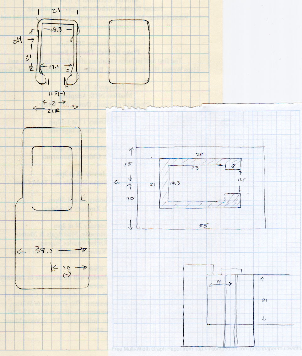
The original doodles, with initial dimensions & some bad ideas:

Comments
3 responses to “MPCNC: Bar Clamp Mounts”
Looks interesting. I’m having trouble visualizing how that works. Got pics?
[…] various prototypes of the bar clamp mounts, here’s the left-side clamp in […]
[…] the new thermistor installed and the nozzle at (pretty nearly) the right height, the final set of bar clamp mounts came out […]