A flashlight used as a daytime running light must point generally forward and an actual bike headlight must light up the road, so it must sit on an az-el mount. My old bike helmet mirror mount had actual vertical and horizontal joints:

Every doodle along those lines seemed too big, too fragile, too fiddly, or all at once.
Living here in the future, though, we can produce (crude) ball joints to order:
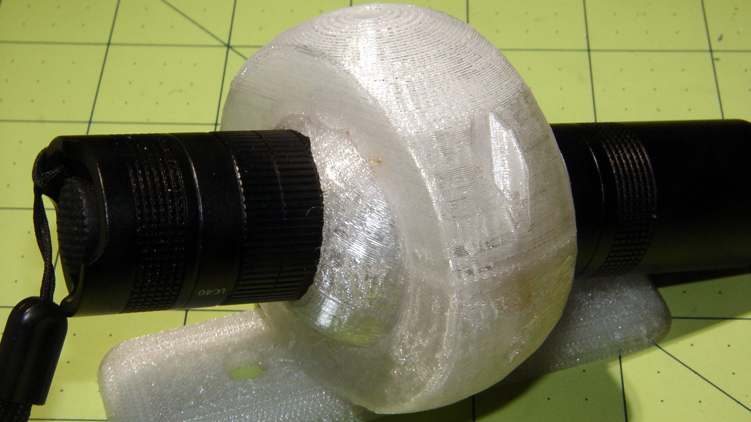
That’s an early version of the outer mount using threaded brass inserts.
The ball around the flashlight separates along the obvious plane of symmetry, with a 2 mm socket-head cap screw and brass insert on each side. I tried printing the hemispheres convex-side-up with hand-hewn support structures inside:
The huge overhanging sections parallel to the axis didn’t bond to the supports, curled upward, and began nudging the dangling Z-axis homing switch actuator. This wasn’t a completely wasted effort, though, as similar support structures came in handy for the outer clamp ring.
Flipping the hemispheres over so they printed U-channel upward didn’t work much better, even sitting on a flat section to eliminate the absurd part of the overhang. This view shows one hemisphere with the missing cap:
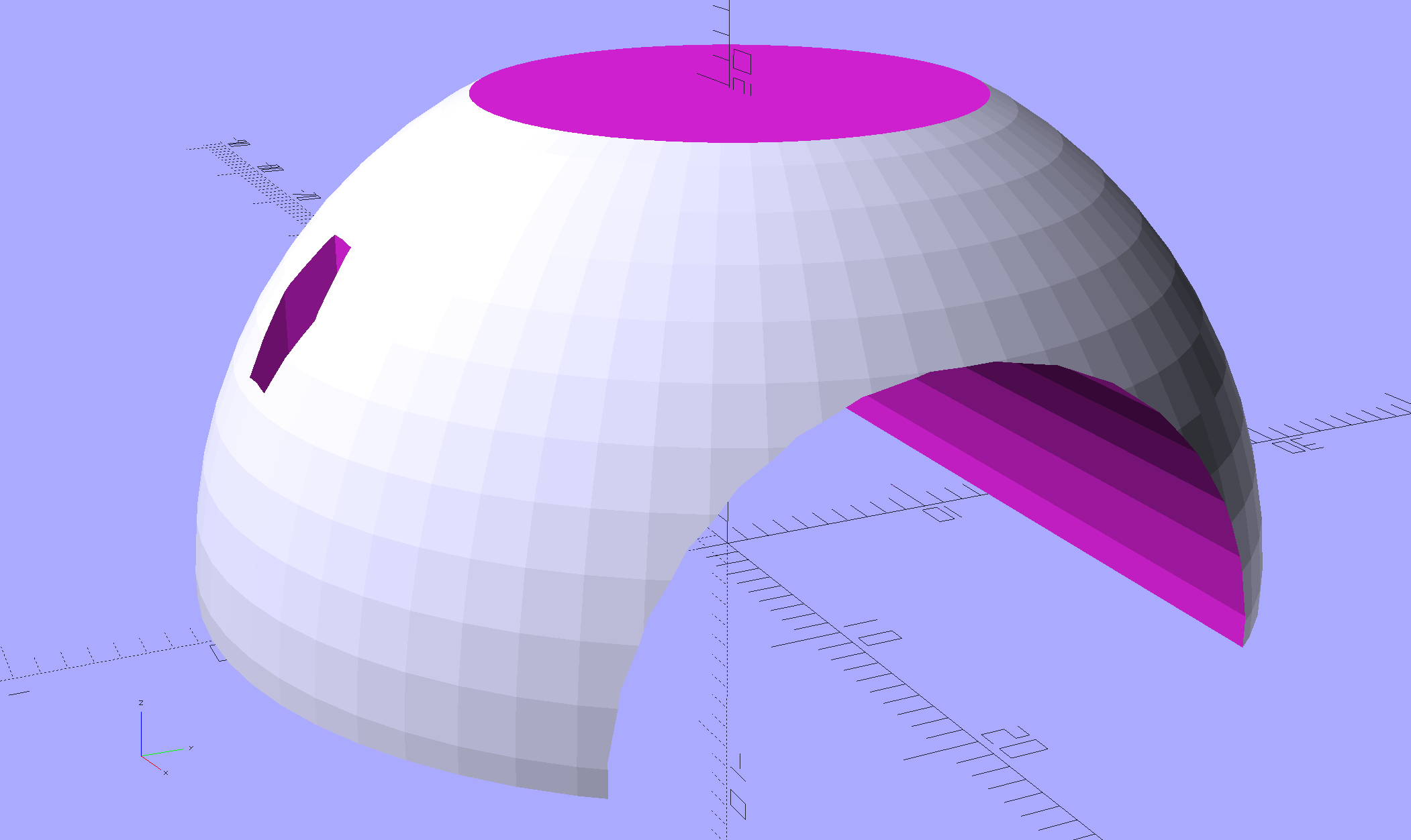
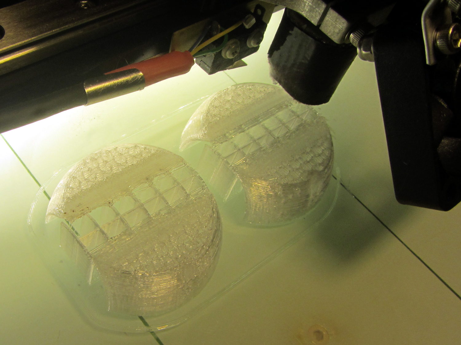
Flipped over, the flat surface bonded perfectly to the platform, but the overhang still warped as the upper layers cooled and pulled the perimeter upward:

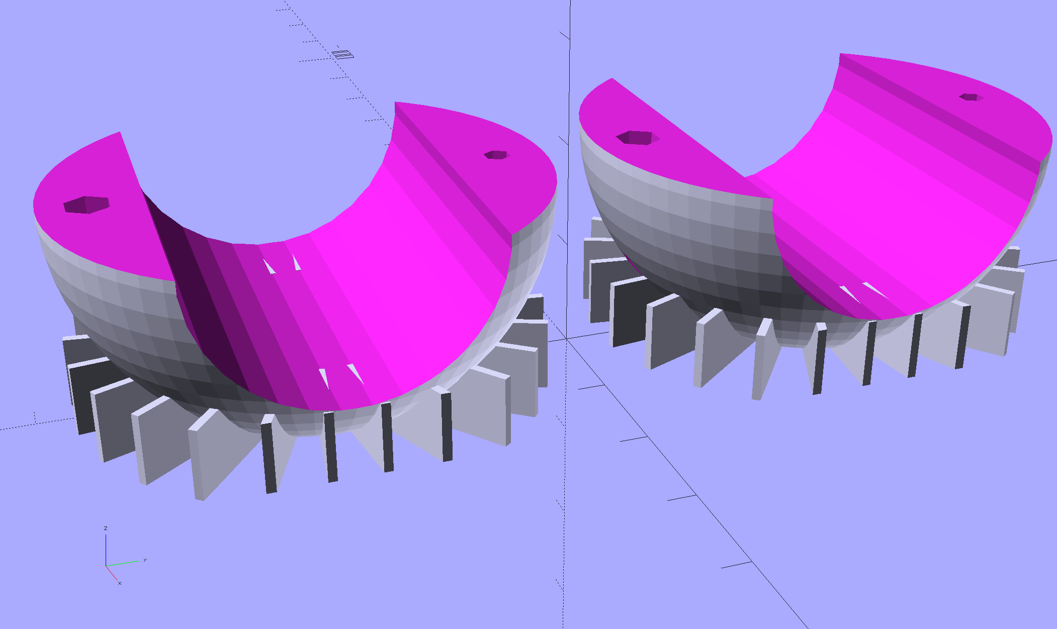
Because normal support structures don’t contact the outer surface, I added fins to the model to hold the perimeter (almost) flat until the outer walls became sufficiently vertical to stop warping:
They’re fearsome hedgehogs in person:
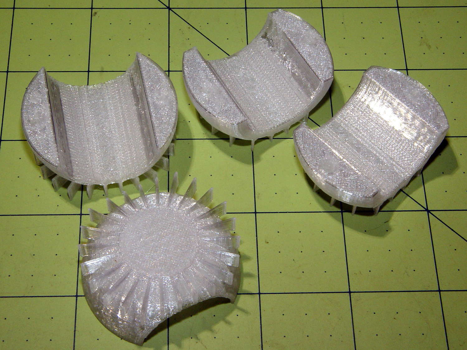
The grip diameter determines the sphere diameter, as the sphere must have enough meat next to the grip to hold the screws and inserts. Rather than have the diameter different for every flashlight, I set it to the maximum of 45 mm or the actual diameter, which means all the flashlights in my collection have a common ball size. The hemispheres on the right have flattened ends to accommodate flashlight grips shorter than the sphere’s final diameter, achieved with a pair of intersection() operations lopping off the protruding bits:
| //- Ball around flashlight | |
| // Must print two! | |
| module BodyBall() { | |
| difference() { | |
| intersection() { | |
| sphere(d=BallOD,$fn=2*NumSides); // basic ball | |
| cube([BallLength,2*BallOD,2*BallOD],center=true); // max of flashlight grip length | |
| } | |
| translate([-LightBodies[FlashIndex][F_GRIPOD],0,0]) | |
| rotate([0,90,0]) rotate(180/NumSides) | |
| PolyCyl(LightBodies[FlashIndex][F_GRIPOD],2*BallOD,NumSides); // flashlight body | |
| for (j=[-1,1]) | |
| translate([0,j*BallScrewOC/2,0]) // commmon screw offset | |
| translate([0,0,-BallOD]) | |
| PolyCyl(BallInsert[ID],2*BallOD,6); // punch screw shaft through everything | |
| translate([0,BallScrewOC/2,-Protrusion]) | |
| PolyCyl(BallInsert[OD],(BallInsert[LENGTH] + 3*ThreadThick + Protrusion),6); // threaded insert | |
| translate([0,-BallScrewOC/2,BallThick]) | |
| PolyCyl(BallScrew[OD],BallOD,6); // screw head clearance | |
| translate([0,0,-BallOD/2]) // remove bottom half | |
| cube(BallOD,center=true); | |
| translate([0,0,BallOD – BallThick/2]) // slice off top = bottom for E-Z build | |
| cube(BallOD,center=true); | |
| } | |
| if (Support) { | |
| NumRibs = 24; | |
| RibHeight = (BallOD – LightBodies[FlashIndex][F_GRIPOD]/cos(180/NumSides) – BallThick) / 2; | |
| ChordC = 2*sqrt(BallThick*BallOD/2 – pow(BallThick/2,2)); | |
| intersection() { | |
| cube([BallLength,2*BallOD,2*BallOD],center=true); // max of flashlight grip length | |
| translate([0,0,BallOD/2 – BallThick/2]) | |
| for (i=[0:NumRibs – 1]) | |
| rotate(i*360/NumRibs + 180/NumRibs) // avoid screw holes | |
| translate([ChordC/2 + BallOD/8,0,-RibHeight/2]) | |
| cube([BallOD/4,2*ThreadWidth,RibHeight],center=true); | |
| } | |
| } | |
| } |
Because the fins extend from resolutely convex surfaces, I snipped them off with flush-cutting pliers, reamed out the holes, epoxied the inserts in place, assembled the ball, and introduced it to Mr Belt Sander.
Protip: don’t hold the ball with your finger through the hole. It will eventually fly off under the workbench and it’s better if it doesn’t break your finger in the process.
A somewhat rough outer surface turns out to be an advantage, not a liability, as the clamp ring around the ball must hold it against the normal (and unusually severe) vibrations found on a bike.
The inner cylindrical section is smooth enough to require a wrap of tape around the flashlight grip to anchor it in position. The tape adheres to the flashlight and squishes into the ball’s layer lines, even under mild pressure from the 2 mm screws. The outer clamp ring applies compression to the ball, so the tiny screws need not withstand much force at all, which is a good thing.

Comments
10 responses to “Tour Easy Daytime Running Light: Flashlight Ball”
I’d have gone with old inner tube instead of tape – less sticky mess to clean up in the future :)
Recently I optimized my ABS printing by adding a (passively) heated enclosure. It gets around 40-45C in there and now it works great, but I had a lot of curling initially. It turned out that curling is not the same as warping even though it looks similar. Then I added the cooling fan to the profile and it works like crazy – just as easy as printing PLA. My point, your curling might be from too much heat, not from normal warping.
You’re certainly right: those two small disks don’t provide enough time for either one to cool before the nozzle returns.
I gave up using the platform fan early last winter, when such a brisk breeze in a cold basement tripped the firmware’s thermal runaway detection, even after upping the limit to 6 °C. Now, with a warmer basement, the platform temperature still drops by too much to make me comfortable.
I should try the old air pump trick for pinpoint cooling at the nozzle, without much air flowing over the platform, because fitting a shroud around the nozzle seems overly complex.
Aquarium pump sounds promising, though it’s news to me. Must try it on the next iteration.
As for bed, I’m using ~5kg aluminium plate so a flimsy 50mm turbine fan stands no chance of cooling it down. Just to be sure, thermistor is burried off to the back on the bottom side so local variations get averaged out before they reach it. Plate that heavy is out of the question on M2 with moving bed unfortunately. But try using an old cardboard box as an enclosure, at least as an experiment. Later you can make one out of steel sheet and have a true fire proof printer :)
Nozzle is sensitive to agressive part cooling. Mine is dressed in a silicone boot that prevents that and ugly black deposits all over the block. If you model your hotend I can mould one for you when I do the next batch.
I like the silicone boot idea. There’s already a silicone-and-fiberglass sleeve around the hot end, with the nozzle extending below:

I (think I still) have some high-temperature RTV silicone around here, so I can try molding a nozzle shield as part of the aquarium pump upgrade. May take a while, though, as I’ve been avoiding some must-do things. [mutter]
That nozzle looks absolutly HUGE so it can probably withstand quite a bit of airflow. What hotend is that?
My E3D v6 nozzles are much smaller (7mm across the flats hex).
Take care with molding RTV, as it releases acid during cure which attacks copper and aluminium. I printed the moulds because of that. At first I couldn’t get silicone to release from the plastic, but coating it in plain dish soap solved that and reduced the cure time significantly. Grant Thompson (aka King of random of Youtube fame) mixed RTV with food coloring and got very fast cure times on account of water in the coloring so just adding a few drops of water might do the trick.
It’s the stock Makergear V4, with 11 mm flats tucked up inside the sleeve.
A simple mold should work better than just buttering up the snout with a thin layer of silicone, although I doubt the acetic acid will do more than tarnish the (already crusty) brass. Nothing like a good new project to distract me from all the other projects …
Definitely go with both inner and outer mold and clamp them together (I’ve put a screw through the nozzle opening). There’s no way to get anything resembling smooth surface othervise. I left a hole in the outer mold and injected silicone straight from the tube until it started coming out the other way. No trapped air bubbles that way. Took six iterations to get the e3d block moulded correctly and separator to actually separate :)
[…] outside being a spherical section, the overhangs will curl upward, so (as with the ball around the flashlight) rows of fins anchor the perimeter […]
[…] mount upward by 20° with respect to the fairing clamp aims the flashlight straight ahead, with the ball nearly centered in the […]
[…] original ball around the flashlight consisted of two identical parts joined with 2 mm screws and brass […]