Ed Nisley's Blog: Shop notes, electronics, firmware, machinery, 3D printing, laser cuttery, and curiosities. Contents: 100% human thinking, 0% AI slop.
The fundamental limit comes from the heater’s ability to bring cold plastic up to extrusion temperature inside the 20 mm hot zone.
Using airscape’s example, the extruded thread is 0.5 mm thick × 0.8 mm wide = 0.4 mm², so laying down that thread at 50 mm/s means the extruder is heating plastic at 20 mm³/s and is “pushing it with PLA”.
In round numbers, normal printing speeds with a normal nozzle and normal plastics runs around 10 mm³/s, so a practical upper limit is probably around 15 mm³/s.
As far as thread size goes, the diameter of the flat area around the nozzle orifice sets the maximum thread width, because the nozzle must compress the thread against the previous layer. If the thread is wider than the nozzle, the gooey plastic curls up around the sides of the nozzle and doesn’t bond well. The rule of thumb is to round up the orifice diameter to the next convenient number:
0.35 mm nozzle → 0.4 mm thread
0.75 mm nozzle → 0.8 mm thread
The maximum thread (= layer) thickness should be about 60% of the thread width, which is why a 0.8 mm wide thread calls for a 0.5 mm layer thickness.
Assuming the extruder can heat 15 mm³/s of plastic, the maximum printing speed will be 15 mm³/s / 0.4 mm² = 37.5 mm/s: comfortably under airscape’s “pushing it” 50 mm/s.
Aaaaand, as always, calibrate the Extrusion Multiplier for whatever conditions you’re using to ensure the slicer and the hardware agree on how much plastic is coming out of the nozzle.
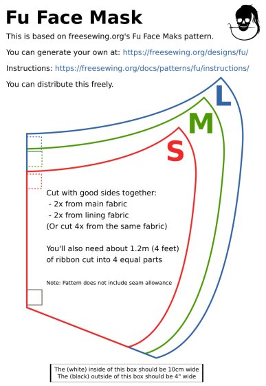
A local hospital contacted Mary’s quilting group to sew up cloth covers to prolong the life of their medical-grade N95 masks. Their recommended pattern, the Fu Face Mask from the FreeSewing group, comes in three sizes:
Freesewing – Fu Mask
N.B.: Use their original PDF, because a JPG picture probably won’t come out at the right size.
Also N.B.: Used by itself, this is not a medical-grade filter mask.
The patterns do not include the usual 1/4 inch seam allowance around the outside, so I cranked out 3D printed plastic cutting templates.
If you’re not interested in 3D printing, 2D print the PDF file on cardboard, sketch a seam allowance, and cut it out, as quilters have been doing since slightly after home printers happened.
The plan of attack:
Convert mask outlines into a bitmap image (GIMP)
Create Bezier curves by tracing outlines (Inkscape)
Save curves as SVG files
Convert SVG into solid model (OpenSCAD)
Add stiffening ribs &c
Save as STL solid model
Slice into G-Code file (Slic3r)
Fire the M2!
So, we begin …
Import the PDF into The GIMP, delete the text & suchlike, convert to monochrome, and save the pattern outlines as a PNG file:
Fu Facemask – outlines
It turns out Inkscape can directly import the PDF, but it valiantly tries to convert all the text and the incidental graphic elements, none of which will be useful in this situation. It’s easier to delete them in The GIMP and make a bank shot off a PNG file.
Import the PNG into Inkscape and trace one outline with the Bezier curve tool:
Fu Mask – Inkscape Bezier trace
If you squint really carefully, you’ll see Bezier control handles sticking out of the nodes. I laid three nodes along the top arc and four along the right side, but do what’cha like; the Insert key or Shift+I inserts and Delete removes nodes. It’s easier to center a node in the middle of the PNG line with snapping turned off: Shift+drag while mousing or globally with #.
You could unleash the bitmap auto-tracer, but it generates a bazillion uselessly tiny Bezier curves.
When you’re happy, select and copy the path with Ctrl+C, paste it into a shiny new Inkscape document (Ctrl+N) with Ctrl-V, save it with a catchy file name like Fu Mask - Small - nominal.svg, and close that document to return to the document with the PNG outlines and the original path.
Select the original path again, create a dynamic offset with Ctrl+J, open the XML editor with Ctrl+Shift+X (which automagically selects the proper SVG element), and change the inkscape:radius value from 0 to 6.35 (mm, which everyone should use) to get a 1/4 inch seam allowance:
Fu Mask – Inkscape XML Editor – Offset radius
The path will puff out with curved corners:
Fu Mask – Inkscape offset
Copy into a new document, save as Fu Mask - Small - seam allowance.svg, and close.
Repeat that process for each of the three mask sizes to create three pairs of SVG files: the nominal mask outline and the corresponding seam allowance outline for each size.
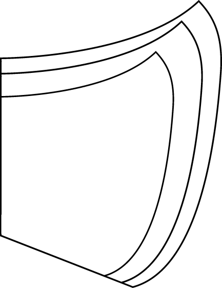
The OpenSCAD program imports the SVG files, removes the nominal outline from within the seam allowance to leave the outline, adds stiffening ribs, and stamps an ID letter on both sides of the central button:
Fu Mask Cutting Template – Small – solid model
Choose one of the three sizes with the OpenSCAD customizer, save the resulting model as an STL file, repeat for the three sizes, and you’re done.
This process can convert any outline paths in SVG files into cutting templates, so, should the Fu Mask not suit your fancy, Use The Source.
For convenience, the STL files are on Thingiverse.
This file contains hidden or bidirectional Unicode text that may be interpreted or compiled differently than what appears below. To review, open the file in an editor that reveals hidden Unicode characters.
Learn more about bidirectional Unicode characters
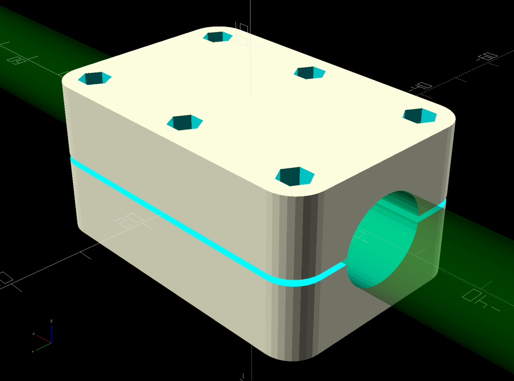
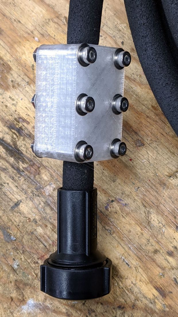
One of two new round rubber soaker hoses arrived with a slight crimp, enough to suggest it would crumble at an inopportune moment. Rather than return the hose for something that’s not an obvious failure, I clamped the crimp:
Round Soaker Hose Splice – top
Unlike the clamps for the punctured flat soaker hoses, this one doesn’t need to withstand much pressure and hold back a major leak, so I made the pieces a bit thicker and dispensed with the aluminum backing plates:
This file contains hidden or bidirectional Unicode text that may be interpreted or compiled differently than what appears below. To review, open the file in an editor that reveals hidden Unicode characters.
Learn more about bidirectional Unicode characters
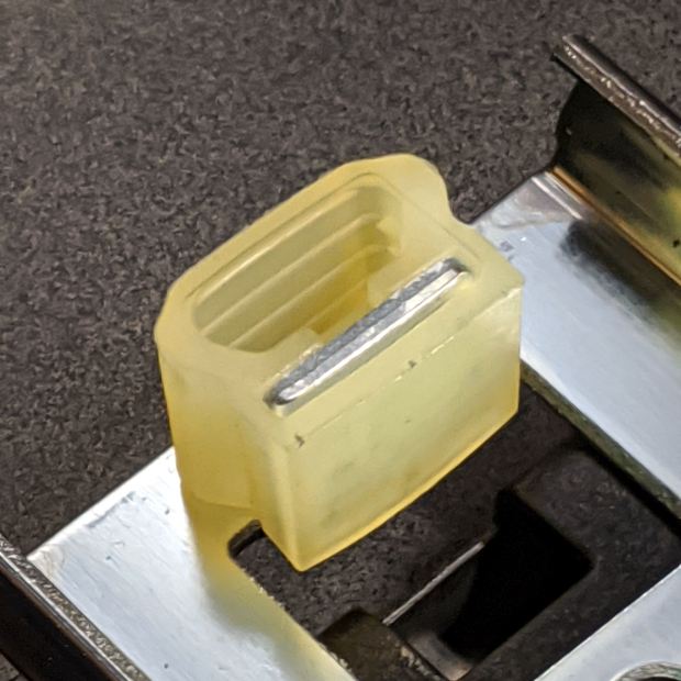
After sliding the HON Lateral File Cabinet shelf into place and installing the bumpers, it seemed rather loose and floppy. Comparing the situation with the other file cabinet showed it had a missing glide button in the rear and two missing slides at the front.
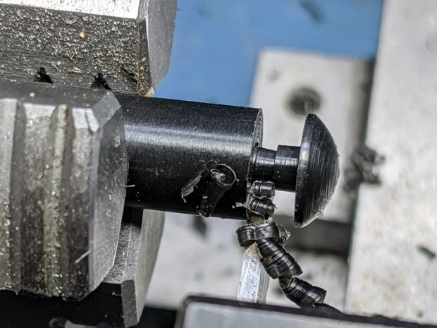
A replacement button emerged from the end of a Delrin rod:
HON Lateral File – shelf button – parting off
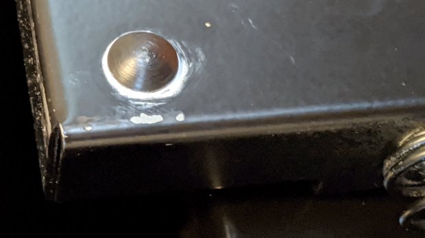
The original buttons had an expanding stem, which is easy to do with an injection-molded part. I opted for simple adhesive, with enough of a blob underneath the shelf to (presumably) lock it in place forevermore:
HON Lateral File – shelf button – installed
The slides required an iterative design technique (pronounced “fumbling around”), because nothing on either side remained square / plumb / true / unbent. I hacked the first version from scrap acrylic, broke off anything that didn’t fit, and got better measurements from what remained:
HON Lateral File – shelf front guide – size test
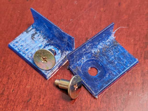
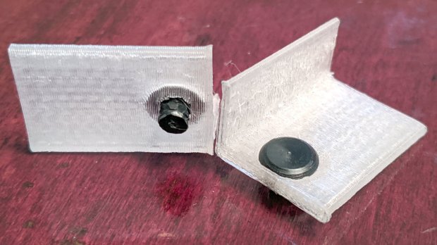
With those measurements in hand, the second version used a pair of weird flat-head shoulder screws (probably from a hard drive) to anchor 3D printed angle brackets into the frame:
HON Lateral File – shelf slides – version 2
Those worked reasonably well, but PETG doesn’t produce a nice sliding surface, so the final version has flat-head Delrin studs in slightly tweaked brackets:
HON Lateral File – shelf slides – version 3
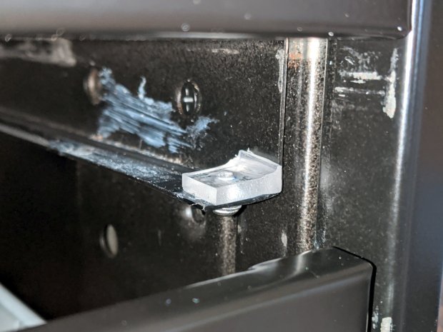
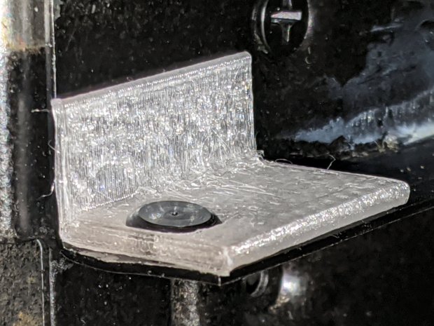
As with the buttons in the back, the original slides had expanding studs holding them in place, but glue works fine here, too:
HON Lateral File – shelf slides – version 3 – installed
The button isn’t quite square to the surface and the slide isn’t quite flush with the bent metal in the frame, but it’s Good Enough™ for a shelf that won’t get lots of mileage.
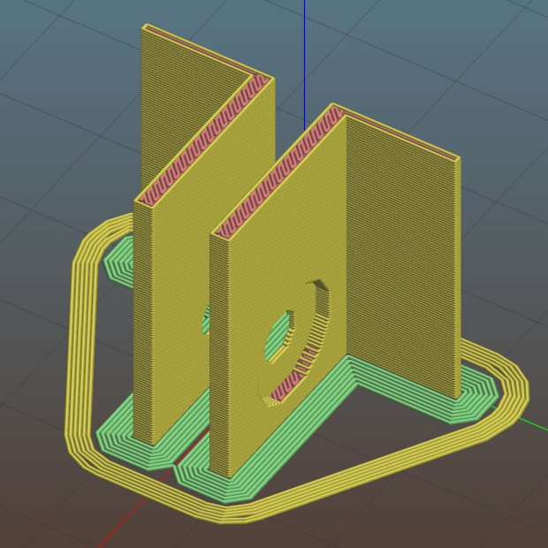
For reference, the brackets should print vertically to wrap the plastic threads around the upright for better strength:
HON Lateral File Shelf Slide – Slic3r
If you did it the obvious way, the upright side would break right off at the first insult from the hulking shelf, although they’re basically a solid chip of plastic, with a little infill inside the bottom slab.
While I was at it, I pulled the springs to make them a bit longer, so they touch the back of the frame when the shelf is half an inch behind the front face of the drawers. A firm push and those Delrin contact points let the shelf pop out an inch or so, with plenty of room for fingers underneath the front edge.
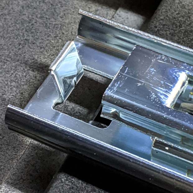
Some drawer slide stops near the back needed attention, too:
HON Lateral File – slide stop bumper – bent
I cannot imagine how hard somebody slammed the drawers, because bending the stops back to a right angle required a Vise-Grip and some muttering:
HON Lateral File – slide stop bumper
Oddly, the cushiony hollow side faces away from the drawer, toward the back of the frame, because putting it forward holds the drawer front proud of the front frame face. Maybe HON cost-reduced the steel slides by making them just slightly shorter and using the same bumpers?
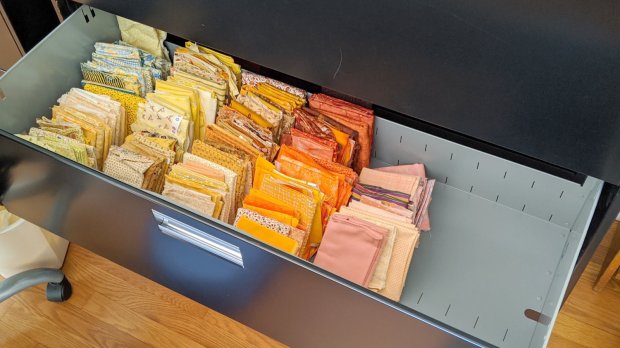
The drawers have begun filling up from boxes scattered around the house:
HON Lateral File – fabric stash
That’s the “orange” part of Mary’s collection, now with plenty of room to grow!
This file contains hidden or bidirectional Unicode text that may be interpreted or compiled differently than what appears below. To review, open the file in an editor that reveals hidden Unicode characters.
Learn more about bidirectional Unicode characters
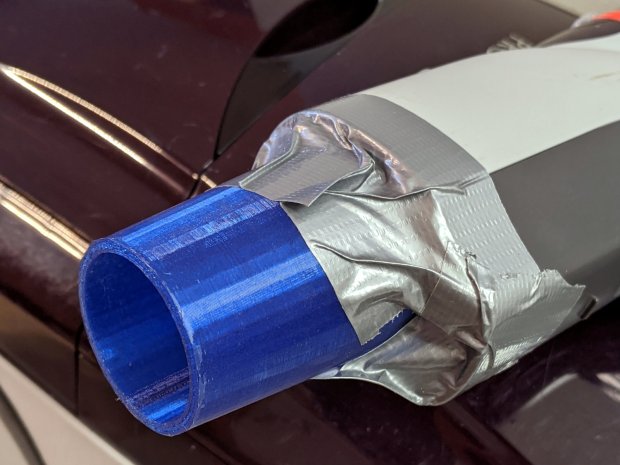
A better fix required a few minutes of OpenSCAD tweakage and a few hours of hands-off build time:
Refrigerator Coil Wand Adapter – Slic3r preview
The fitting ID is now 2 mm smaller, the 3D honeycomb infill is 25%, and (contrary to the picture) it now has 4 perimeter threads. It’s a two-line change from the last time:
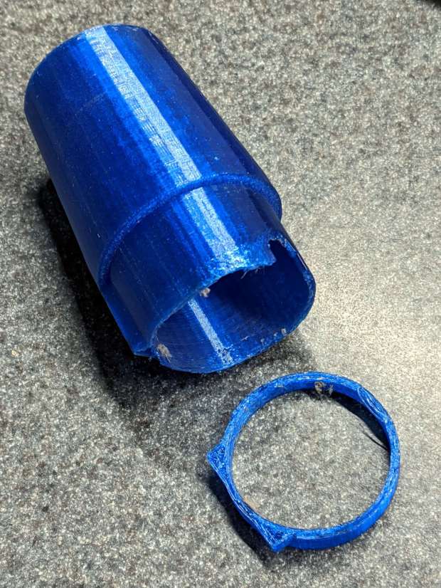
Another reducer had gone missing over the years, so I made one from a length of PVC pipe:
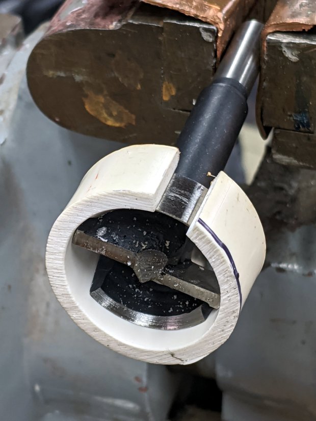
Bird Box – PVC pipe reducer – shaping
It started as 1-½ PVC pipe, 1-⅞ inch actual OD and should fit into a 1-½ hole, so I measured 1.5 × 3.15 around the circumference, bandsawed out the excess, draped it over a 1-½ Forstner bit, toasted it with a heat gun, and squashed it so it’s just a little bit bigger than the (enlarged!) hole in the box.
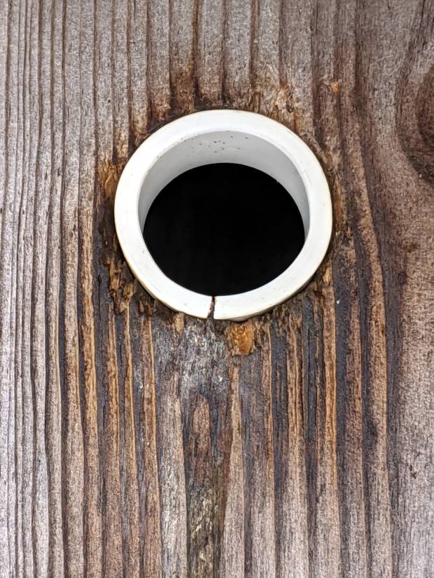
Now the entrance is 1-¼ (-ish), just like it should be:
Bird Box – PVC pipe reducer – installed
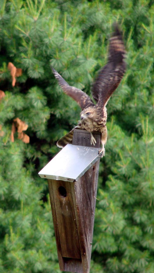
The bird box in the front yard has been attracting starlings, in addition to serving as a hawkperch:
New Coopers Hawks – bird box takeoff whoops
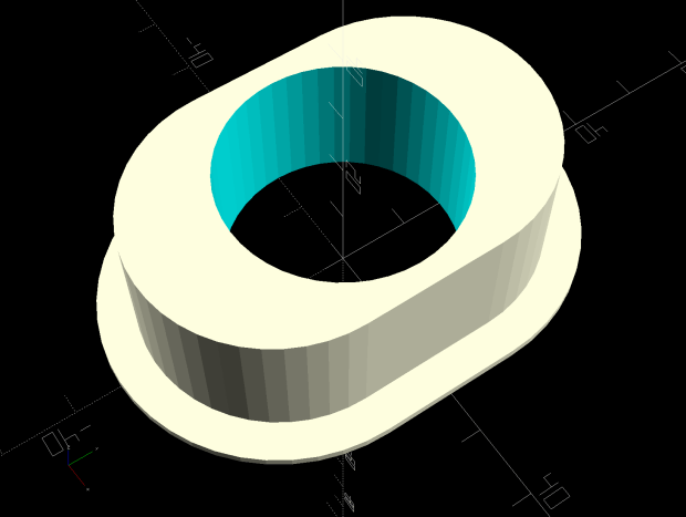
The oblong hole required advanced manufacturing techniques:
Oval Entrance Reducer
The front face should be too slick for larger birds and the little ones will zip right into the hole:
Bird Box – 3D printed entrance reducer
The two starlings who’d been evaluating the box seem to have moved on; we doubt they’re now homeless.
This file contains hidden or bidirectional Unicode text that may be interpreted or compiled differently than what appears below. To review, open the file in an editor that reveals hidden Unicode characters.
Learn more about bidirectional Unicode characters
A new spool of retina-burn orange PETG snagged when the takeup guide let the filament fall off the inboard side and the extruder tightened the loops around the spool holder. I carefully unwound the loops without removing the spool to ensure I didn’t introduce a crossover, scraped the bird’s next off the platform, and restarted the print.
After undoing the second snag, I added a crude spool sidewall: