The Smell of Molten Projects in the Morning

Ed Nisley's Blog: Shop notes, electronics, firmware, machinery, 3D printing, laser cuttery, and curiosities. Contents: 100% human thinking, 0% AI slop.

Tag: M2

Using and tweaking a Makergear M2 3D printer

  • Soaker Hose End Plug

    Soaker Hose End Plug

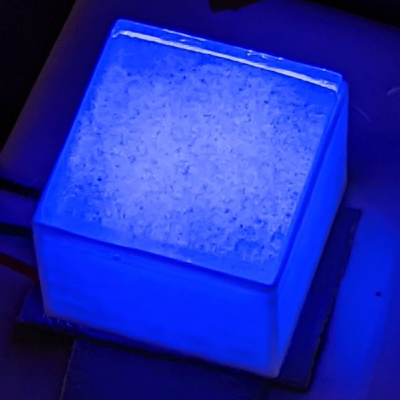
    One of the soaker hoses in Mary’s Vassar Farms garden split lengthwise near one end:

    Soaker Hose Plug - hose split
    Soaker Hose Plug – hose split

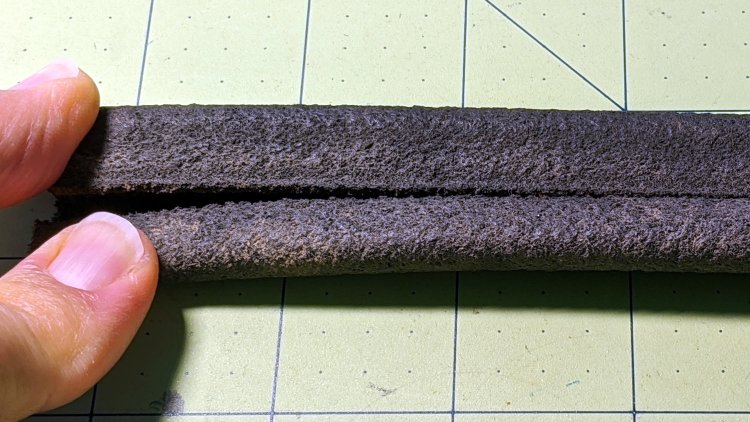
    Although the hose is fully depreciated, I thought it’d be worthwhile to cut off the damaged end and conjure an end cap to see if a simple plug can withstand 100 psi water pressure.

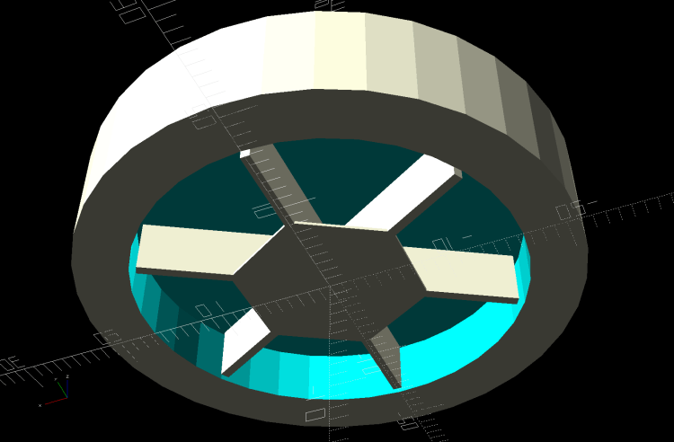
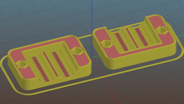
    A pair of Delrin (because I have it) plugs with serrations fill the hose channels, with the outer clamp squishing the hose against them:

    Soaker Hose Plug - channel plugs - side view
    Soaker Hose Plug – channel plugs – side view

    In real life, they’ll be pushed completely into the hose, with a generous layer of silicone snot caulk improving their griptivity.

    I started with 8 mm plugs, but they didn’t quite fill the channels:

    Soaker Hose Plug - channel plugs - 8 mm test fit
    Soaker Hose Plug – channel plugs – 8 mm test fit

    Going to 8.5 mm worked better, although there’s really no way to force the granulated rubber shape into a snug fit around a cylinder:

    Soaker Hose Plug - channel plugs test fit
    Soaker Hose Plug – channel plugs test fit

    Fortunately, they need not be leakproof, because leaking is what the hose does for a living. Well, did for a living, back before it died.

    The clamps have a solid endstop, although it’s more to tidy the end than to hold the plugs in place:

    Soaker Hose End Plug - Slic3r
    Soaker Hose End Plug – Slic3r

    The clamps need aluminum backing plates to distribute the stress evenly across their flat sides:

    Soaker Hose Plug - installed
    Soaker Hose Plug – installed

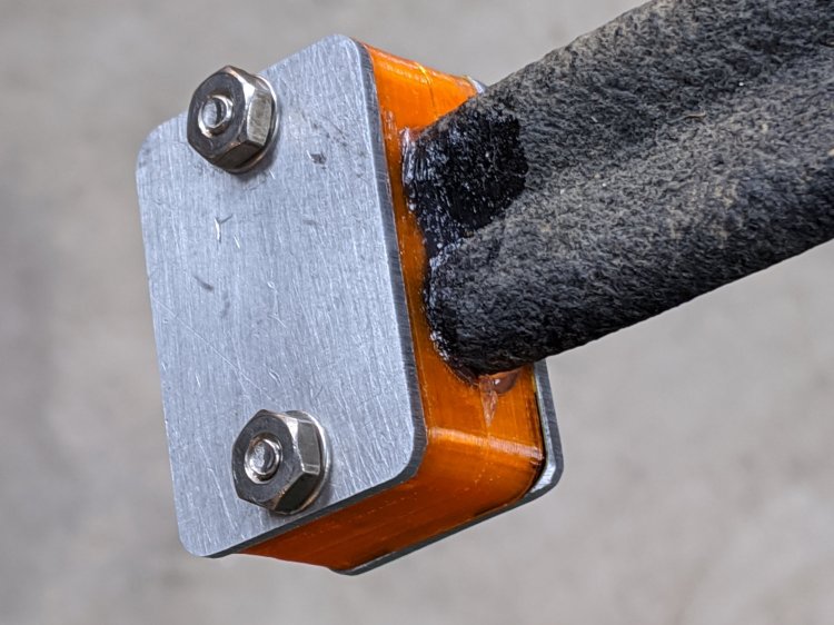
    Those are 8-32 stainless steel screws. The standard 1 inch length worked out exactly right through no fault of my own.

    The OpenSCAD source code as a GitHub Gist:

    // Rubber Soaker Hose End Plug
    // Ed Nisley KE4ZNU June 2019
    // 2020-05 Two-channel hose end plug
    Layout = "Hose"; // [Hose,Block,Show,Build]
    //- Extrusion parameters must match reality!
    /* [Hidden] */
    ThreadThick = 0.25;
    ThreadWidth = 0.40;
    HoleWindage = 0.2;
    Protrusion = 0.1; // make holes end cleanly
    inch = 25.4;
    function IntegerMultiple(Size,Unit) = Unit * ceil(Size / Unit);
    //———-
    // Dimensions
    // Hose lies along X axis
    HoseTubeOD = 12.0; // water tube diameter
    HoseTubeOC = 12.5; // .. spacing
    HoseWebThick = 7.8; // center joining tubes
    Hose = [100,25.0,HoseTubeOD]; // X=very long, Y=overall width, Z=thickness
    HoseSides = 12*4;
    PlugLength = 25.0; // plugs in hose channels
    PlateThick = 5.0; // end block thickness
    WallThick = 2.0; // overall minimum thickness
    Kerf = 0.75; // cut through middle to apply compression
    ID = 0;
    OD = 1;
    LENGTH = 2;
    // 8-32 stainless screws
    Screw = [4.1,8.0,3.0]; // OD = head LENGTH = head thickness
    Washer = [4.4,9.5,1.0];
    Nut = [4.1,9.7,6.0];
    CornerRadius = Washer[OD]/2;
    ScrewOC = Hose.y + Washer[OD];
    echo(str("Screw OC: ",ScrewOC));
    BlockOAL = [PlugLength + PlateThick,ScrewOC + Washer[OD],2*WallThick + Hose.z]; // overall splice block size
    echo(str("Block: ",BlockOAL));
    //———————-
    // Useful routines
    module PolyCyl(Dia,Height,ForceSides=0) { // based on nophead's polyholes
    Sides = (ForceSides != 0) ? ForceSides : (ceil(Dia) + 2);
    FixDia = Dia / cos(180/Sides);
    cylinder(d=(FixDia + HoleWindage),h=Height,$fn=Sides);
    }
    // Hose shape
    module HoseProfile() {
    rotate([0,-90,0])
    translate([0,0,-Hose.x/2])
    linear_extrude(height=Hose.x,convexity=4)
    union() {
    for (j=[-1,1]) // outer channels
    translate([0,j*HoseTubeOC/2])
    circle(d=HoseTubeOD,$fn=HoseSides);
    translate([0,0])
    square([HoseWebThick,HoseTubeOC],center=true);
    }
    }
    // Outside shape of splice Block
    // Z centered on hose rim circles, not overall thickness through center ridge
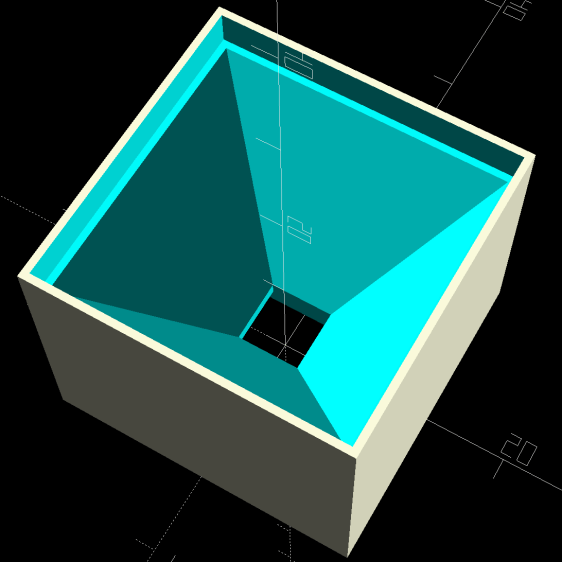
    module SpliceBlock() {
    difference() {
    hull()
    for (i=[-1,1], j=[-1,1]) // rounded block
    translate([i*(BlockOAL.x/2 – CornerRadius),j*(BlockOAL.y/2 – CornerRadius),-BlockOAL.z/2])
    cylinder(r=CornerRadius,h=BlockOAL.z,$fn=4*8);
    for (j=[-1,1]) // screw holes
    translate([0,
    j*ScrewOC/2,
    -(BlockOAL.z/2 + Protrusion)])
    PolyCyl(Screw[ID],BlockOAL.z + 2*Protrusion,6);
    cube([2*BlockOAL.x,2*BlockOAL.y,Kerf],center=true); // slice through center
    }
    }
    // Splice block less hose
    module ShapedBlock() {
    difference() {
    SpliceBlock();
    translate([(-Hose.x/2) + (BlockOAL.x/2) – PlateThick,0,0])
    HoseProfile();
    }
    }
    //———-
    // Build them
    if (Layout == "Hose")
    HoseProfile();
    if (Layout == "Block")
    SpliceBlock();
    if (Layout == "Show") {
    ShapedBlock();
    translate([(-Hose.x/2) + (BlockOAL.x/2) – PlateThick,0,0])
    color("Green",0.25)
    HoseProfile();
    }
    if (Layout == "Build") {
    SliceOffset = 0;
    intersection() {
    translate([SliceOffset,0,BlockOAL.z/4])
    cube([4*BlockOAL.x,4*BlockOAL.y,BlockOAL.z/2],center=true);
    union() {
    translate([0,0.6*BlockOAL.y,BlockOAL.z/2])
    ShapedBlock();
    translate([0,-0.6*BlockOAL.y,BlockOAL.z/2])
    rotate([0,180,0])
    ShapedBlock();
    }
    }
    }

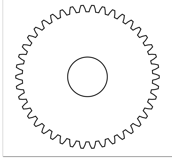
    The original doodle, with dimensions vaguely related to the final model:

    Soaker Hose End Plug - hose dimensions
    Soaker Hose End Plug – hose dimensions

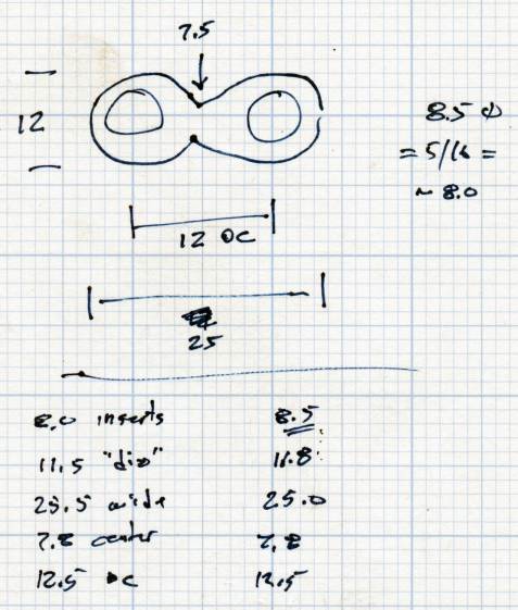
    There is, as far as I can tell, no standardization of dimensions or shapes across manufacturers, apart from the threaded hose fittings.

  • Glass Tiles: 2×2 Matrix

    Glass Tiles: 2×2 Matrix

    Start with a single cell holding a glass tile over a WS2812 RGB LED:

    Glass Tile - 1x1 cell test - purple phase
    Glass Tile – 1×1 cell test – purple phase

    A bit of OpenSCAD tinkering produces a simple 2×2 array with square interiors as a test piece:

    Glass Tile - 2x2 - PETG strings
    Glass Tile – 2×2 – PETG strings

    The excessive stringing and the booger in the upper-left cell come from absurdly thin infill tucked into the too-thin walls; Slic3r doesn’t (seem to) have a “minimum infill width” setting and it’ll desperately try to fit infill between two nearly adjacent perimeter threads.

    The little support spiders under the LED PCB recesses snapped right out, though, so I got that part right:

    Glass Tile - 2x2 - support spiders
    Glass Tile – 2×2 – support spiders

    The perimeter threads around the LED aperture aren’t quite fused, because it was only one layer thick and that’s not enough.

    A quick test with two LEDs showed the white PETG let far too much light bleed between the cells, which was no surprise from the single cell test piece.

    Fortunately, it’s all parametric, so a bit more tinkering produced a slightly chunkier matrix with a base for an Arduino Nano and M3 threaded brass inserts for the screws holding it together:

    Glass Tile Frame - 2x2 - Arduino Nano base - solid model
    Glass Tile Frame – 2×2 – Arduino Nano base – solid model

    Those two parts require about three hours of printing, much faster than I could produce them by milling pockets into aluminum or black acrylic slabs, and came out with minimal stringing.

    A little cleanup, some epoxy work, and a few dabs of solder later:

    Glass Tile - 2x2 - Arduino wiring
    Glass Tile – 2×2 – Arduino wiring

    An initial lamp test showed the white-ish glass tiles aren’t all quite the same color:

    Glass Tile - 2x2 - white color variation
    Glass Tile – 2×2 – white color variation

    I thought it was an LED color variation, too, but the slightly blue tint in the lower left corner followed the tile.

    The blurred horizontal strip across the middle is adhesive tape holding the tiles in place; I was reluctant to glue them in before being sure this whole thing would work. A peek into the future, though, shows it’s got potential:

    Glass Tile - 2x2 - first two units
    Glass Tile – 2×2 – first two units

    They do give off a definite Windows logo vibe, don’t they?

    The OpenSCAD source code as a GitHub Gist:

    // Illuminated Tile Grid
    // Ed Nisley – KE4ZNU
    // 2020-05
    /* [Configuration] */
    Layout = "Build"; // [Cell,CellArray,MCU,Base,Show,Build]
    Shape = "Square"; // [Square, Pyramid, Cone]
    Cells = [2,2];
    CellDepth = 15.0;
    Support = true;
    Inserts = true;
    /* [Hidden] */
    ThreadThick = 0.25;
    ThreadWidth = 0.40;
    HoleWindage = 0.2;
    function IntegerMultiple(Size,Unit) = Unit * ceil(Size / Unit);
    Protrusion = 0.1; // make holes end cleanly
    ID = 0;
    OD = 1;
    LENGTH = 2;
    Tile = [25.0 + 0.1,25.0 + 0.1,4.0];
    WallThick = 3*ThreadWidth;
    Flange = [4*ThreadWidth,4*ThreadWidth,0]; // ridge supporting tile
    Separator = [3*ThreadWidth,3*ThreadWidth,Tile.z – 1]; // between tiles
    Screw = [3.0,6.0,3.5]; // M3 SHCS, OD=head, LENGTH=head
    Insert = [3.0,4.2,8.0]; // threaded brass insert
    PCB = [15.0,8.0,2.5];
    LED = [5.0 + 2*HoleWindage,5.0 + 2*HoleWindage,1.0];
    LEDOffset = [0.0,(PCB.y – LED.y)/2 – 0.5,0.0]; // slight offset from +Y PCB edge
    CellOAL = [Tile.x,Tile.y,0] + Separator + [0,0,CellDepth] + [0,0,WallThick] + [0,0,PCB.z];
    ArrayOAL = [Cells.x*CellOAL.x,Cells.y*CellOAL.y,CellOAL.z]; // just the LED cells
    BlockOAL = ArrayOAL + [2*WallThick,2*WallThick,0]; // LED cells + exterior wall
    echo(str("Block OAL: ",BlockOAL));
    InsertOC = ArrayOAL – [Insert[OD],Insert[OD],0] – [2*WallThick,2*WallThick,0];
    echo(str("Insert OC: ",InsertOC));
    TapeThick = 1.0;
    Arduino = [44.0,18.0,8.0 + TapeThick]; // Arduino Nano to top of USB Mini-B plug
    USBPlug = [15.0,11.0,8.5]; // USB Mini-B plug insulator
    USBOffset = [0,0,5.5]; // offset from PCB base
    WiringBay = [BlockOAL.x – 4*WallThick,38.0,3.0];
    PlateOAL = [BlockOAL.x,BlockOAL.y,WallThick + Arduino.z + WiringBay.z];
    echo(str("Base Plate: ",PlateOAL));
    //————————
    module PolyCyl(Dia,Height,ForceSides=0) { // based on nophead's polyholes
    Sides = (ForceSides != 0) ? ForceSides : (ceil(Dia) + 2);
    FixDia = Dia / cos(180/Sides);
    cylinder(d=(FixDia + HoleWindage),h=Height,$fn=Sides);
    }
    //———————–
    // Base and optics in single tile
    module LEDCone() {
    hull() {
    translate([0,0,CellDepth + Tile.z/2])
    cube(Tile – [Flange.x,Flange.y,0],center=true);
    if (Shape == "Square") {
    translate([0,0,LED.z/2])
    cube([Tile.x,Tile.y,LED.z] – [Flange.x,Flange.y,0],center=true);
    }
    else if (Shape == "Pyramid") {
    translate([0,0,LED.z/2])
    cube(LED,center=true);
    }
    else if (Shape == "Cone") {
    translate([0,0,LED.z/2])
    cylinder(d=1.5*LED.x,h=LED.z,center=true);
    }
    else {
    echo(str("Whoopsie! Invalid Shape: ",Shape));
    cube(5);
    }
    }
    }
    // One complete LED cell
    module LEDCell() {
    difference() {
    translate([0,0,CellOAL.z/2])
    cube(CellOAL,center=true);
    translate([0,0,CellOAL.z – Separator.z + Tile.z/2])
    cube(Tile,center=true);
    translate([0,0,PCB.z + WallThick])
    LEDCone();
    cube([LED.x,LED.y,CellOAL.z],center=true);
    translate(-LEDOffset + [0,0,PCB.z/2 – Protrusion/2])
    cube(PCB + [0,0,Protrusion],center=true);
    }
    if (Support)
    color("Yellow") render()
    translate(-LEDOffset) {
    // translate([0,0,ThreadThick/2])
    // cube([PCB.x – 2*ThreadWidth,PCB.y – 2*ThreadWidth,ThreadThick],center=true);
    intersection() {
    translate([0,0,(PCB.z – ThreadThick)/2])
    cube([PCB.x – 2*ThreadWidth,PCB.y – 2*ThreadWidth,PCB.z – ThreadThick],center=true);
    union() { for (a=[0:22.5:359])
    rotate(a)
    translate([PCB.x/2,0,PCB.z/2])
    cube([PCB.x,2*ThreadWidth,PCB.z],center=true); }
    }
    }
    }
    // The whole array of cells
    module CellArray() {
    difference() {
    union() {
    translate([CellOAL.x/2 – Cells.x*CellOAL.x/2,CellOAL.y/2 – Cells.y*CellOAL.y/2,0])
    for (i=[0:Cells.x – 1], j=[0:Cells.y – 1])
    translate([i*CellOAL.x,j*CellOAL.y,0])
    LEDCell();
    if (Inserts) // bosses
    for (i=[-1,1], j=[-1,1])
    translate([i*InsertOC.x/2,j*InsertOC.y/2,0])
    rotate(180/8)
    cylinder(d=Insert[OD] + 3*WallThick,h=Insert[LENGTH],$fn=8);
    }
    if (Inserts) // holes
    for (i=[-1,1], j=[-1,1])
    translate([i*InsertOC.x/2,j*InsertOC.y/2,-Protrusion])
    rotate(180/8)
    PolyCyl(Insert[OD],Insert[LENGTH] + WallThick + Protrusion,8);
    }
    difference() {
    translate([0,0,CellOAL.z/2])
    cube(BlockOAL,center=true);
    translate([0,0,CellOAL.z])
    cube(ArrayOAL + [0,0,2*CellOAL.z],center=true);
    }
    }
    // Arduino bounding box
    // Origin at center bottom of PCB
    module Controller() {
    union() {
    translate([0,0,Arduino.z/2])
    cube(Arduino,center=true);
    translate([Arduino.x/2 – Protrusion,-USBPlug.y/2,USBOffset.z + TapeThick – USBPlug.z/2])
    cube(USBPlug + [Protrusion,0,0],center=false);
    }
    }
    // Baseplate
    module BasePlate() {
    difference() {
    translate([0,0,PlateOAL.z/2])
    cube(PlateOAL,center=true);
    translate([0,0,WallThick])
    Controller();
    translate([0,0,WallThick + PlateOAL.z/2])
    cube([Arduino.x – 2*2.0,WiringBay.y,PlateOAL.z],center=true);
    translate([0,0,PlateOAL.z – WiringBay.z + WiringBay.z/2])
    cube(WiringBay + [0,0,2*Protrusion],center=true);
    for (i=[-1,1], j=[-1,1])
    translate([i*InsertOC.x/2,j*InsertOC.y/2,-Protrusion])
    rotate(180/8) {
    PolyCyl(Screw[ID],2*PlateOAL.z,8);
    PolyCyl(Screw[OD],Screw[LENGTH] + 4*ThreadThick + Protrusion,8);
    }
    translate([0,0,ThreadThick-Protrusion])
    cube([17.0,45,2*ThreadThick],center=true);
    }
    linear_extrude(height=2*ThreadWidth + Protrusion) {
    translate([1,0,-Protrusion])
    rotate(-90) mirror([1,0,0])
    text(text="Ed Nisley",size=6,font="Arial:style:Bold",halign="center");
    translate([-6.5,0,-Protrusion])
    rotate(-90) mirror([1,0,0])
    text(text="softsolder.com",size=4.5,font="Arial:style:Bold",halign="center");
    }
    if (Support)
    color("Yellow")
    for (i=[-1,1], j=[-1,1])
    translate([i*InsertOC.x/2,j*InsertOC.y/2,0])
    for (a=[0:45:135])
    rotate(a)
    translate([0,0,(Screw[LENGTH] – ThreadThick)/2])
    cube([Screw[OD] – 2*ThreadWidth,2*ThreadWidth,Screw[LENGTH] – ThreadThick],center=true);
    }
    //———————–
    // Build things
    if (Layout == "Cell")
    LEDCell();
    else if (Layout == "CellArray")
    CellArray();
    else if (Layout == "MCU")
    Controller();
    else if (Layout == "Base")
    BasePlate();
    else if (Layout == "Show") {
    translate([0,0,PlateOAL.z + 10])
    CellArray();
    BasePlate();
    }
    else if (Layout == "Build") {
    translate([0,0.6*BlockOAL.y,0])
    CellArray();
    translate([0,-0.6*BlockOAL.y,0])
    rotate(90)
    BasePlate();
    }

  • Glass Tiles: Single Test Cell

    Glass Tiles: Single Test Cell

    A single glass tile rests on the ridge around the pyramidal interior:

    Glass Tile Frame - pyramid cell
    Glass Tile Frame – pyramid cell

    The bottom has a cutout for the WS2812 PCB, with some in-the-model support for simplicity:

    Glass Tile Frame - pyramid cell - bottom
    Glass Tile Frame – pyramid cell – bottom

    Which becomes this in real life:

    Glass Tile - 1x1 cell test - pyramid PETG strings
    Glass Tile – 1×1 cell test – pyramid PETG strings

    There’s plenty of PETG hair inside the opening, which seems like a Bad Thing all around.

    Cleaning out the worst of the fur, taping a WS2812 LED into the opening, and dropping a white-ish tile in place:

    Glass Tile - 1x1 cell test - purple phase
    Glass Tile – 1×1 cell test – purple phase

    Obviously, JPG compression wasn’t built with a finely textured granular surface in mind:

    Glass Tile - 1x1 cell test - blue phase
    Glass Tile – 1×1 cell test – blue phase

    But it looks really nice in a dim room!

    With a physical object in hand, it’s obvious the pyramidal interior adds exactly zero value:

    • Direct rays in the beam from the WS2812 don’t hit the walls
    • Light outside the beam doesn’t contribute much after hitting those irregular walls

    So the next pass should be just a hollow box with tweaked tile & PCB measurement: rapid prototyping in full effect!

  • Pride Lift Chair: Fuzzy Felt Feet

    Pride Lift Chair: Fuzzy Felt Feet

    By the Universal Principle of the Conservation of Perversity, the base of the floor lamp just barely doesn’t fit under the edge of the Comfy Chair:

    Floor Lamp - copper 70° elbow - installed
    Floor Lamp – copper 70° elbow – installed

    Well, I can fix that!

    Lift Chair Foot - installed
    Lift Chair Foot – installed

    The feet descend from the fuzzy felt feet on the plant shelves, with the hex head socket transmogrified into a circle to match the chair feet. The support structure grew a flat plate to ensure it doesn’t pull loose from the platform:

    Lift Chair Feet - solid model - support view
    Lift Chair Feet – solid model – support view

    Print ’em out, stick the felt in place:

    Lift Chair Feet - assembly
    Lift Chair Feet – assembly

    Lift the chair (maybe with a small prybar atop some plywood to protect the floor), position the feet, lower gently: done!

    While the M2 was warm, I ran off another set for the other Comfy Chair, just for symmetry.

    The OpenSCAD source code as a GitHub Gist:

    // Feet for Pride lift chair
    // Ed Nisley KE4ZNU 2020-05
    Layout = "Build"; // [Show, Build]
    Support = true;
    //- Extrusion parameters must match reality!
    // Print with 2 shells and 3 solid layers
    /* [Hidden] */
    ThreadThick = 0.25;
    ThreadWidth = 0.40;
    HoleWindage = 0.2;
    Protrusion = 0.1; // make holes end cleanly
    inch = 25.4;
    //———————-
    // Dimensions
    /* [Dimensions] */
    ChairFootOD = 33.0;
    ChairFootRecess = 5.0;
    FeltOD = 39.0;
    FeltRecess = 2.5;
    FootPlate = 6*ThreadThick;
    FootWall = 4*ThreadWidth;
    FootOD = 2*FootWall + max(ChairFootOD,FeltOD);
    echo(str("Foot OD: ",FootOD));
    FootTall = ChairFootRecess + FootPlate + FeltRecess;
    echo(str(" … height: "),FootTall);
    NumSides = 9*4;
    //———————-
    // Useful routines
    module FootPad() {
    difference() {
    cylinder(r=FootOD/2,h=FootTall,$fn=NumSides);
    translate([0,0,FeltRecess + FootPlate])
    cylinder(d=ChairFootOD,h=2*ChairFootRecess,$fn=NumSides);
    translate([0,0,-Protrusion])
    cylinder(d=FeltOD,h=(FeltRecess + Protrusion),$fn=NumSides);
    }
    }
    //——————-
    // Build it…
    if (Layout == "Show")
    FootPad();
    if (Layout == "Build") {
    translate([0,0,FootTall])
    rotate([180,0,0])
    FootPad();
    if (Support)
    color("Yellow") {
    for (Seg=[0:5])
    rotate(30 + 360*Seg/6)
    translate([0,0,(ChairFootRecess – ThreadThick)/2])
    cube([(ChairFootOD – 3*ThreadWidth),
    2*ThreadWidth,
    (ChairFootRecess – ThreadThick)],
    center=true);
    rotate(180/6)
    cylinder(d=0.5*ChairFootOD,h=ThreadThick,$fn=6);
    }
    }

  • Mini-Lathe Metric Threading: 42 Tooth Gear

    Mini-Lathe Metric Threading: 42 Tooth Gear

    Going from a 21 tooth gear to a 42 tooth gear means you must reduce the remaining train ratio by a factor of two for a given thread pitch. Here’s a 42-50-45-60 train, with the same -125 ppm error as the 21-50-60-40 train and no screw / washer clearance issues between the A screw and the C gear:

    Mini-Lathe change gears - 1 mm - 45-50-45-60
    Mini-Lathe change gears – 1 mm – 45-50-45-60

    The original 60-40 CD pair has a 3:2 ratio, the 45-60 CD pair is 3:4, so that’s where the factor-of-two reduction happens.

    The first pass at the solid model included a debossed legend:

    Mini-lathe 42 tooth change gear - Slic3r
    Mini-lathe 42 tooth change gear – Slic3r

    With a printed gear in hand, I realized the legend must be embossed below the surface, so as not to rub against an adjacent gear; better modeling is in order.

    The general idea is to set Inkscape’s (known-good) gear generator to the correct gear parameters (module 1 → 3.14 mm circular pitch, 20° pressure angle):

    Inkscape Gear Generator dialog
    Inkscape Gear Generator dialog

    Save the outline as an SVG:

    Inkscape Gear Generator result
    Inkscape Gear Generator result

    If you do like I did and neatly position the gear at the bottom-left origin, all SVG viewers will show only the Quadrant I arc, probably because Inkscape sets the SVG file to display it that way. I’ve made that mistake before and maybe, someday, I’ll remember.

    Load the SVG into OpenSCAD, which will find the entire gear, no matter where it falls in the coordinate space, and spike it at the origin:

    linear_extrude(8.0,center=false,convexity=5) 
     import(file="/the-source-directory/Mini-Lathe/Change Gear - 42 teeth.svg",center=true);
    

    The linear_extrude( … center=false … ) keeps the bottom of the blank at Z=0. The import( … center=true … ) puts the 2D shape at the XY origin. Because OpenSCAD centers the bounding box, gears with an odd number of teeth will be ever so slightly off-center, which would matter a whole lot more in a fancier machine tool than a mini-lathe.

    All of which produces a tidy 3D gear blank:

    Mini-lathe change gear - 42 tooth - SVG import
    Mini-lathe change gear – 42 tooth – SVG import

    OpenSCAD ignores SVG holes, which isn’t a problem for me, because I’d rather punch the bore, keyway, and so forth programatically.

    But that’s another story …

  • Mini-Lathe Metric Threading: 32 Tooth Gear

    Mini-Lathe Metric Threading: 32 Tooth Gear

    While not strictly necessary for metric threading on a USA-ian mini-lathe, a 32 tooth gear can produce reasonable approximations, so I printed a pair from a Thingiverse collection:

    Mini-lathe 32 tooth change gear - Slic3r
    Mini-lathe 32 tooth change gear – Slic3r

    The model was designed for a slightly different mini-lathe, as it includes a short boss and thinner plate, but it did fit on the shaft:

    Mini-Lathe change gears - 1 mm - bad 32 60 65 55
    Mini-Lathe change gears – 1 mm – bad 32 60 65 55

    The gear mesh seemed odd, though, and comparing it with a standard 30 tooth gear and a different printed 32 tooth gear (about which, more later) showed it was definitely not compatible:

    Mini-lathe change gears - 32 30 odd 32
    Mini-lathe change gears – 32 30 odd 32

    Yes, the 32 tooth Thingiverse gear on the right is slightly smaller than the stock 30 tooth gear in the middle.

    The larger 32 tooth gear (on the left, above) meshes better:

    Mini-Lathe change gears - 1 mm - 65 55 32 60
    Mini-Lathe change gears – 1 mm – 65 55 32 60

    Both of those trains have a 600 ppm error, so they’re definitely suboptimal compared to the results with a 21 tooth gear in the train.

    The real reason you need a 32 tooth gear is for exact 25, 50, and 100 TPI threads with a 1/16 inch leadscrew. I don’t foresee much need for those around here, but you can never have too many change gears …

  • Nissan Fog Lamp: Desk Stand

    Nissan Fog Lamp: Desk Stand

    The Nissan fog lamp looks pretty good pointing at the ceiling:

    Nissan Fog Lamp - table mount
    Nissan Fog Lamp – table mount

    I briefly considered sandblasting the shell to knock back the corrosion, but came to my senses: this is art!

    The shell has a bayonet mount intended for the cable connector, but a bout of solid modeling produced a matching twist-lock desk stand:

    Nissan Fog Light Base - Slic3r preview
    Nissan Fog Light Base – Slic3r preview

    The locking dogs overhang little enough, relative to their diameter, to let the thing build without internal supports. Took about three hours without any intervention at all.

    The little hole matches up with the slot on the bottom holding a USB cable bringing power from a wall charger:

    Nissan Fog Lamp - table mount interior
    Nissan Fog Lamp – table mount interior

    It’s a knockoff Arduino Pro Mini without the USB interface found on a Nano, so the USB data wires don’t connect to anything.

    The base might look better under a layer of (black?) epoxy, although I’m definitely a fan of those brutalist 3D printed striations.

    The OpenSCAD source code as a GitHub Gist:

    // Nissan Fog Light Base
    // Ed Nisley KE4ZNU 2020-04-20
    /* [Hidden] */
    ThreadThick = 0.25;
    ThreadWidth = 0.40;
    HoleWindage = 0.2;
    function IntegerMultiple(Size,Unit) = Unit * ceil(Size / Unit);
    Protrusion = 0.1; // make holes end cleanly
    //———————-
    // Dimensions
    ID = 0;
    OD = 1;
    LENGTH = 2;
    /* [Fog Light] */
    ShellBase = [49.0,55.0,10.0];
    Dog = [55.0,60.0,7.0];
    DogWidth = 21.0;
    DogAngle = atan(DogWidth / ShellBase[ID]);
    echo(str("Dog angle: ",DogAngle));
    ReflectorOD = 90.0;
    LensOD = 110.0;
    LensAngle = -90; // peak relative to dogs
    WallThick = 4.0;
    BaseThick = 2*WallThick;
    CableOD = 3.5;
    $fn = 3*4*5;
    //——————-
    // Useful shapes
    module Dogs(h=Dog[LENGTH]) {
    translate([0,0,h/2])
    intersection() {
    cube([Dog[OD],DogWidth,h],center=true);
    cylinder(d=Dog[OD],h=h,center=true);
    }
    }
    //——————-
    // Build it
    difference() {
    union() {
    cylinder(d=(Dog[OD] + 2*WallThick),h=(BaseThick + ShellBase[LENGTH]));
    intersection() {
    resize([0,0,2*BaseThick])
    sphere(d=LensOD);
    translate([0,0,BaseThick/2])
    cube([2*LensOD,2*ReflectorOD,BaseThick],center=true);
    }
    }
    translate([0,0,BaseThick])
    cylinder(d=ShellBase[OD],h=ShellBase[LENGTH] + Protrusion);
    translate([0,0,BaseThick]) {
    Dogs();
    rotate(1.5*DogAngle)
    Dogs();
    rotate(2*DogAngle)
    Dogs(2*ShellBase[LENGTH]);
    }
    rotate(LensAngle)
    translate([0.75*ShellBase[ID]/2,0,-Protrusion]) {
    cylinder(d=CableOD,h=2*BaseThick,$fn=8);
    translate([LensOD/2,0,CableOD/2])
    cube([LensOD,CableOD,CableOD + Protrusion],center=true);
    }
    translate([31,0,ThreadThick-Protrusion])
    cube([23.0,55.0,2*ThreadThick],center=true);
    }
    linear_extrude(height=2*ThreadWidth + Protrusion) {
    translate([32,0,-Protrusion])
    rotate(-90) mirror([1,0,0])
    text(text="Ed Nisley",size=6,font="Arial:style:Bold",halign="center");
    translate([23,0,-Protrusion])
    rotate(-90) mirror([1,0,0])
    text(text="softsolder.com",size=5,font="Arial:style:Bold",halign="center");
    }