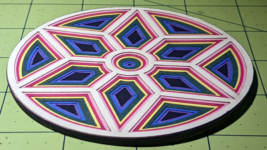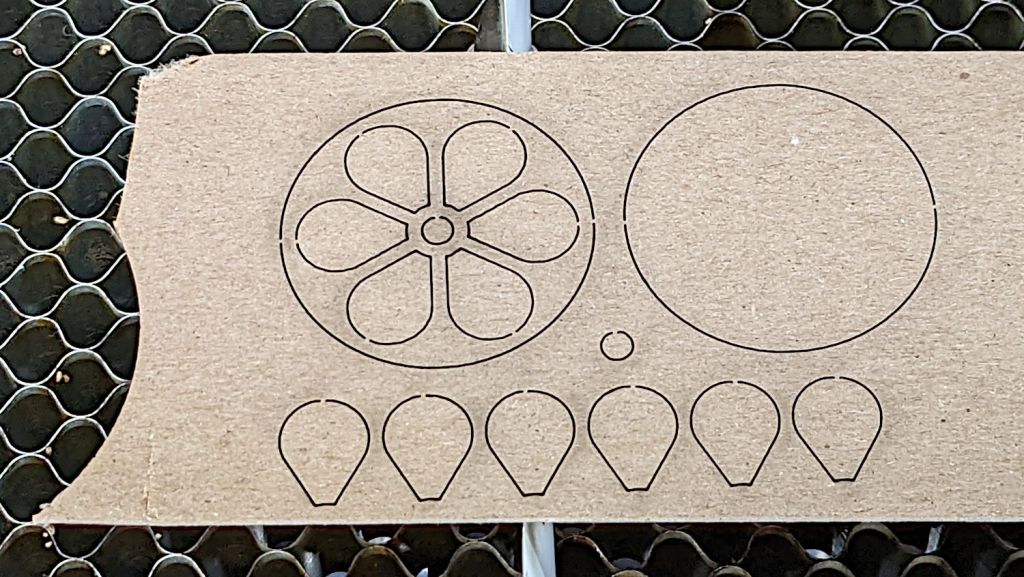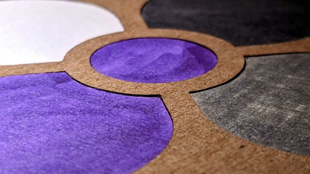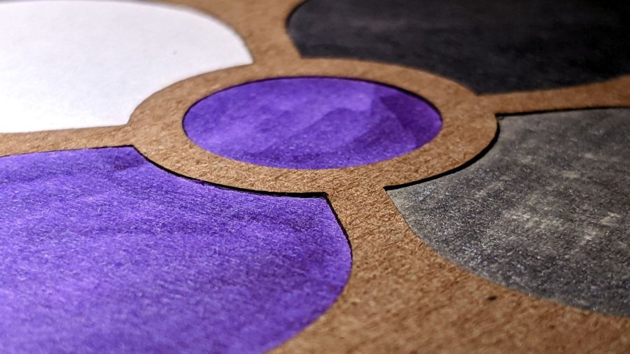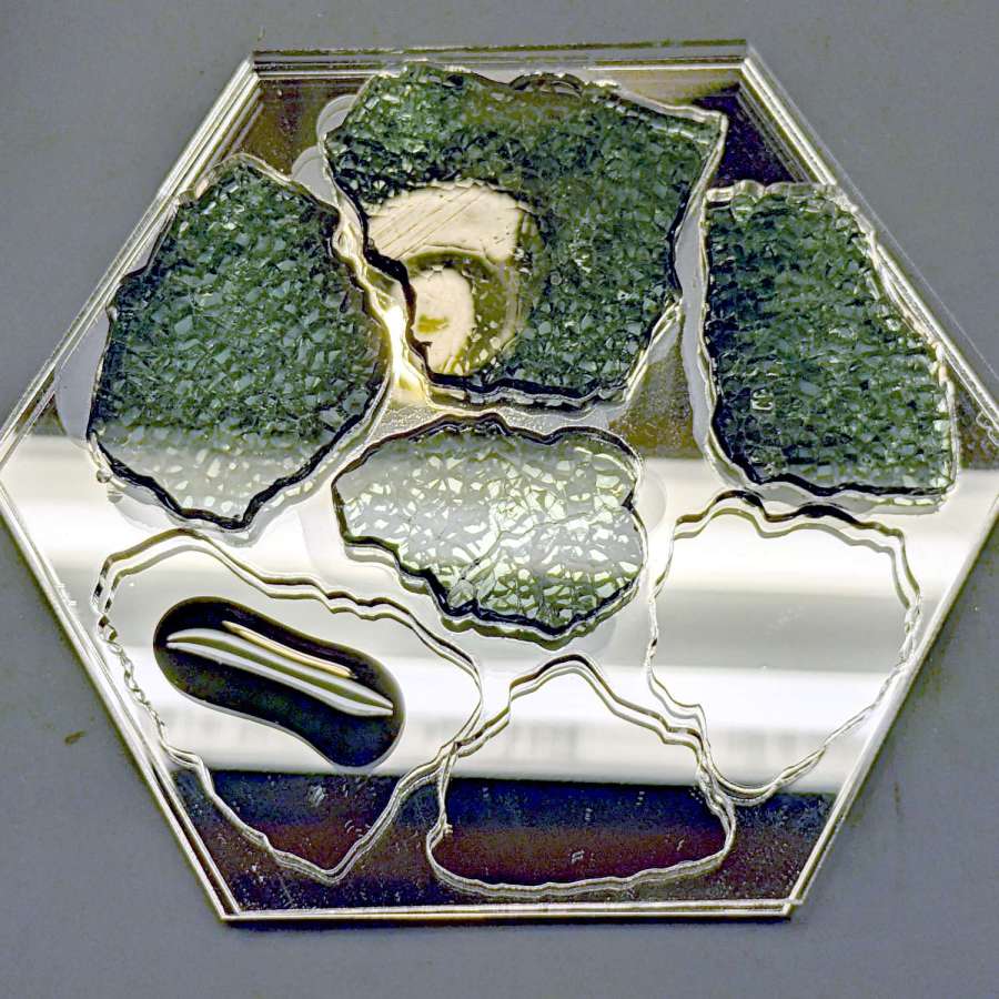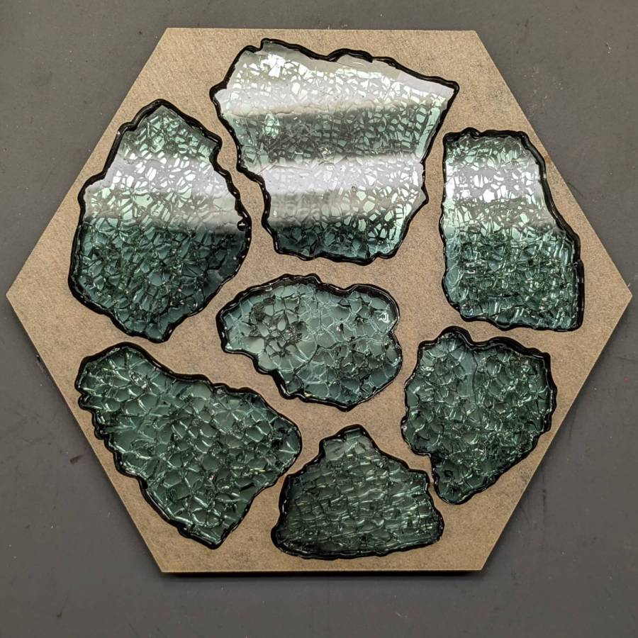
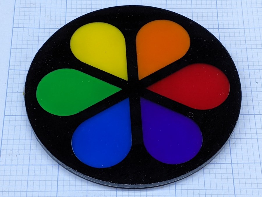
Assembling acrylic pieces inside an epoxy-filled frame produces nice results:
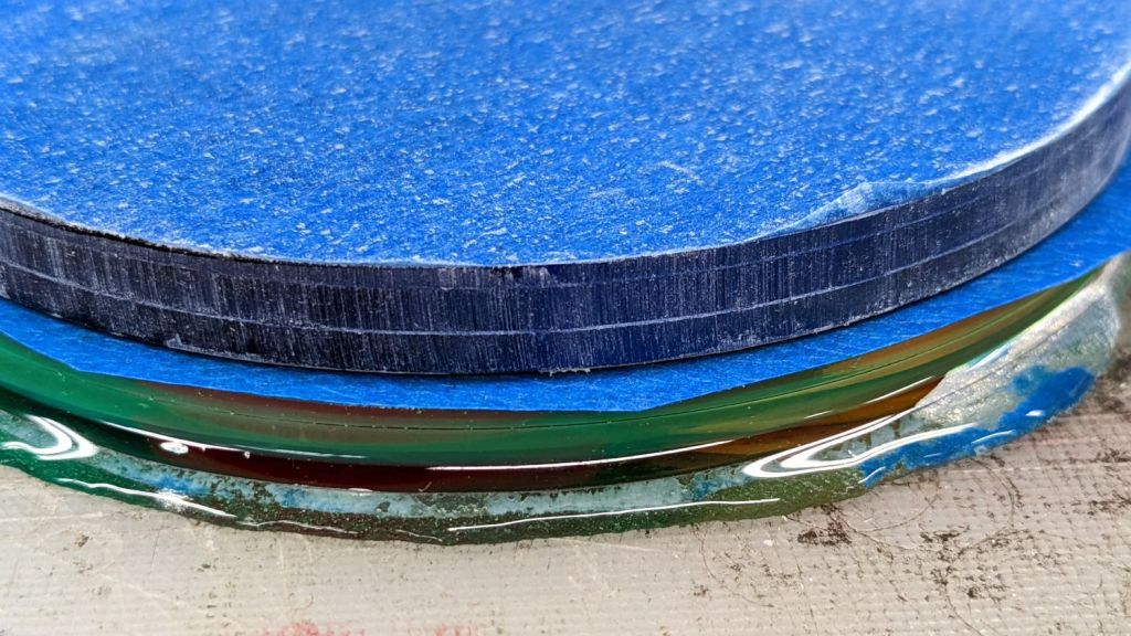
The gotcha: epoxy oozes from between the layers to form a slobbery edge.
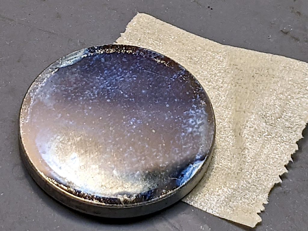
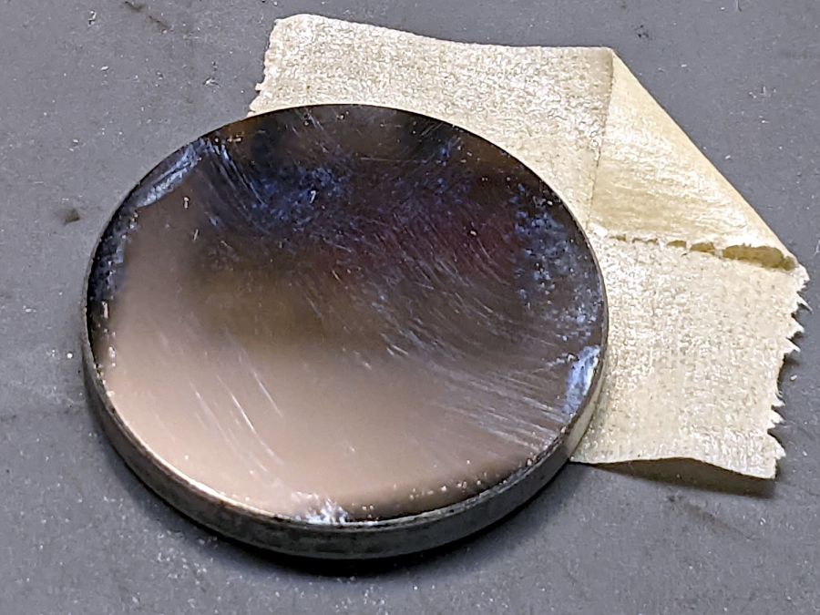
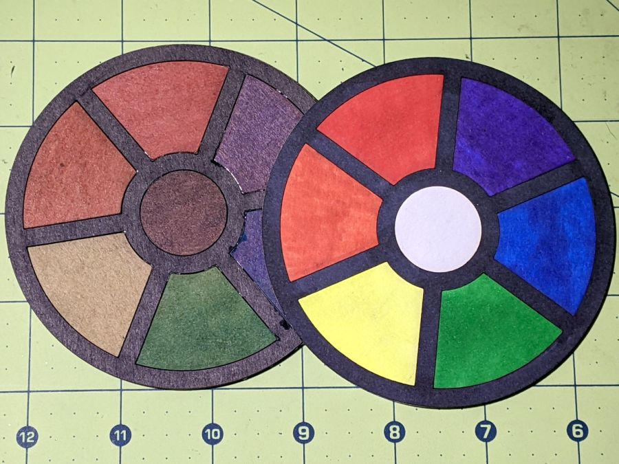
I tried introducing a similar coaster to Mr Disk Sander with reasonable results:
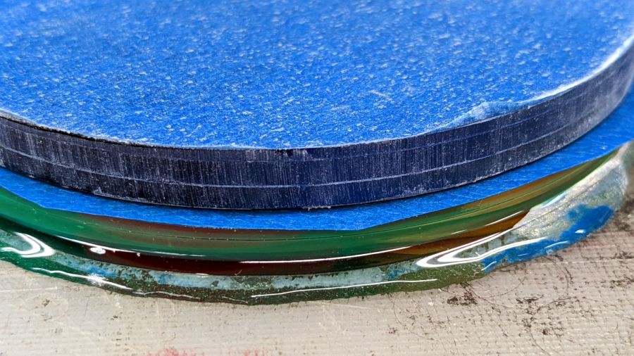
The coaster on the bottom has its original generous epoxy slobber around the acrylic disks.
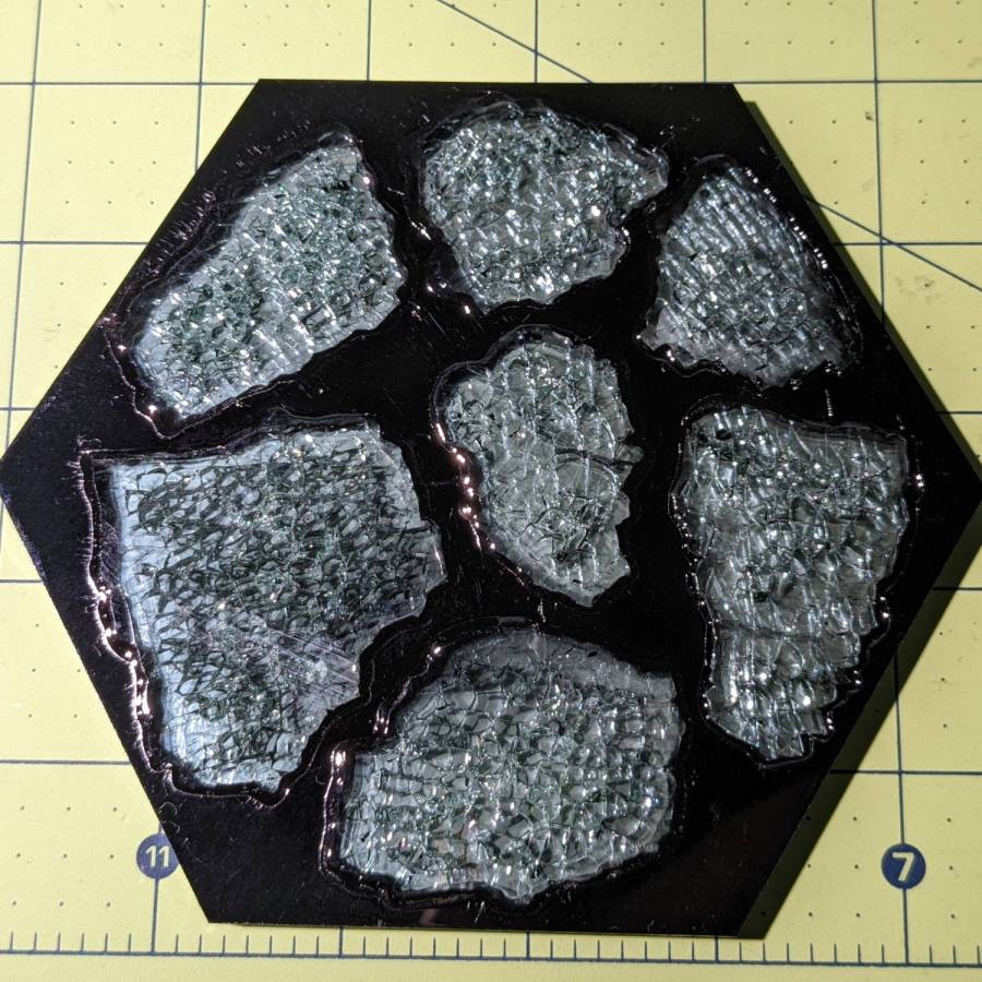
Assembling the layers inside a mold seems fraught with messiness, particularly if I eventually want to get it out of the mold.
Using a finer abrasive disk would certainly help, but the whole process requires intense concentration and is utterly unforgiving of mistakes.
I figured I could attach the coaster to a lathe fixture and turn the rim, so I made a fixture from scrap acrylic:
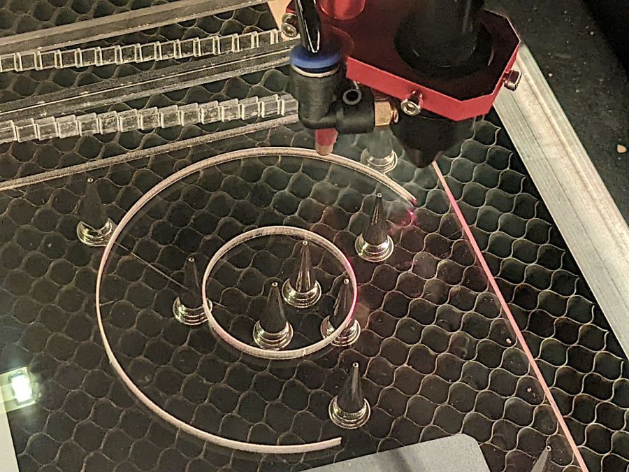
The lathe chuck inside jaws fit inside the hole and I set up to turn the OD to a nice even diameter:
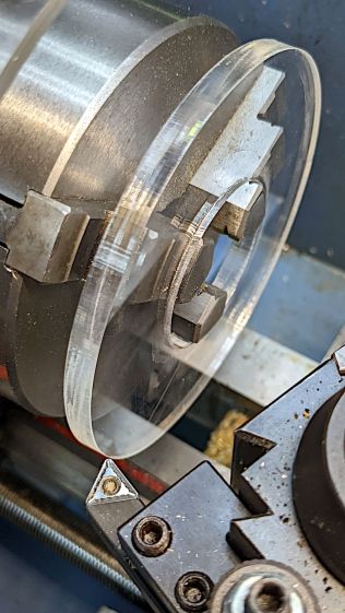
The fixture sat flush against the middle step of the jaws with plenty of clearance from the outer step, so I could turn the OD without whacking the carbide insert.
I planned to grab the OD and turn the ID to a (reasonably) concentric finish, but the outer jaws have an absolute diameter limit a few millimeters less than the 4 inch = 101.4 mm coaster OD.
After some increasingly desperate attempts, I concluded that, lacking a 4-jaw lathe chuck, there was no way to mount the coaster on the fixture and have it sit it even approximately centered on the spindle axis.
I do, however, have a 4-jaw chuck for the Sherline mill, normally used with the rotary table.
Next up: Round 2.