Ed Nisley's Blog: Shop notes, electronics, firmware, machinery, 3D printing, laser cuttery, and curiosities. Contents: 100% human thinking, 0% AI slop.
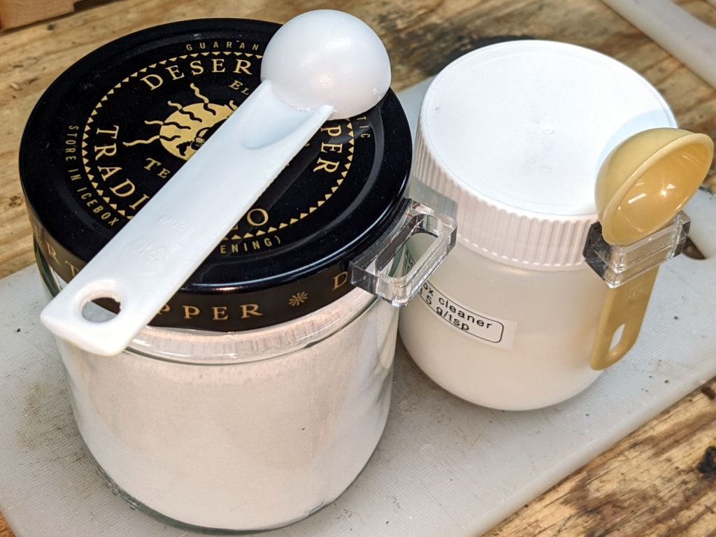
We have accumulated enough measuring spoons (typically from garage sales) to dedicate them for specific purposes, which means keeping them from wandering away:
Jar lid measuring spoon holders
The design is simple enough:
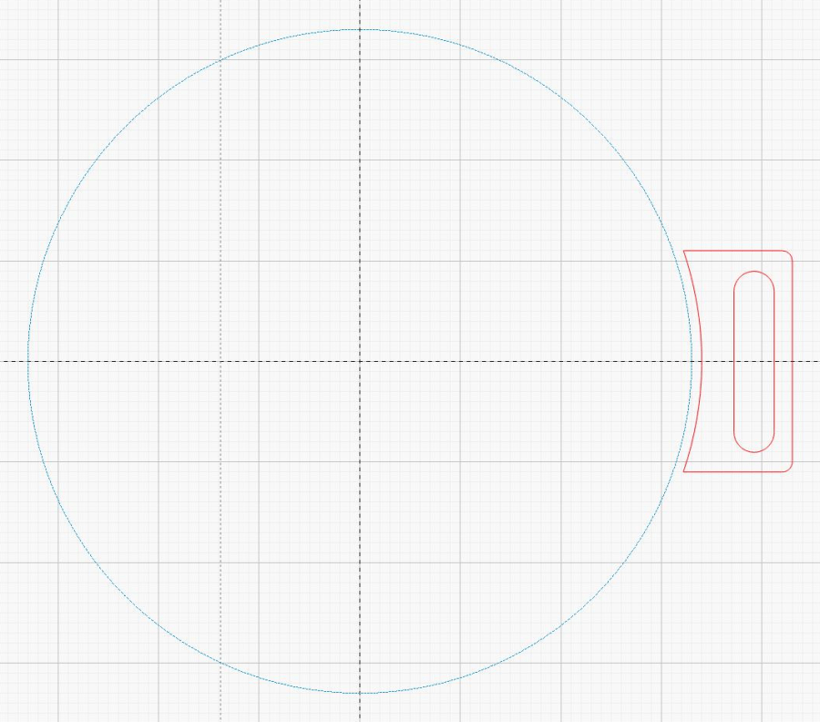
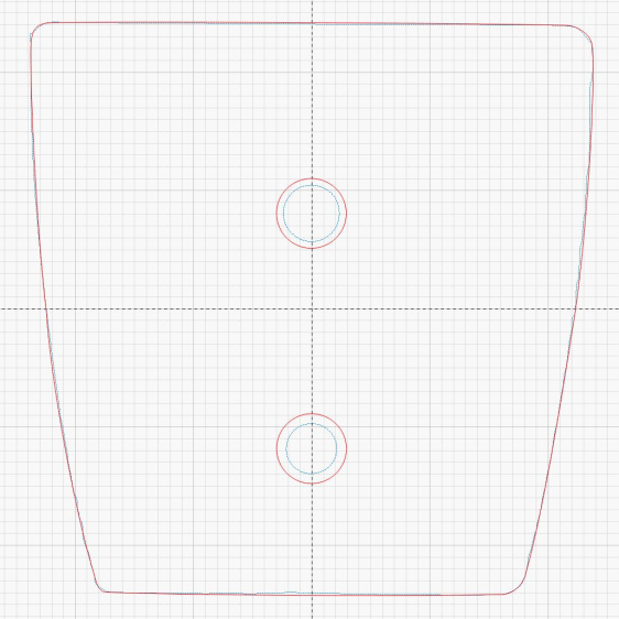
Jar lid measuring spoon holder – LB layout
The slot is a rounded rectangle about 2 mm larger than the spoon handle in both directions, inside a rounded rectangle large enough to put the handle just clear of the jar. The curved side comes from outsetting the jar lid OD by a millimeter (for the double-sided foam tape), then subtracting that circle from the holder.
So, yeah, they’re custom-made for the spoon and jar in hand.
For reasons not relevant here, a hand shower will come in mmm handy for a while in a month or two. The threads on its plastic diverter valve pretty nearly match those on the 70 year old iron pipe in the front bathroom, although the original brass shower head may have been installed by John Henry the Steel-Drivin’ Man.
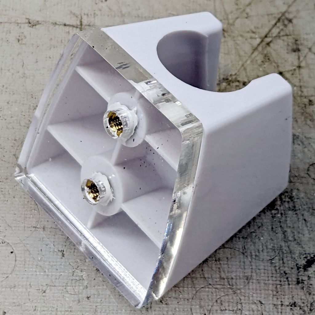
In any event, you’re supposed to drill two screw holes in the wall for the holder, which is just not happening. Instead, scan the bottom of the holder and blow out the contrast for the next step:
Hand Shower bracket – scan
Yes, those holes are off-center in their molded bosses. They’re centered in their front recesses and I cannot imagine how, in this day and age of CAD everything, a designer could misalign the front and the back, but there it is.
A little cleanup produces a reasonable mask:
Hand Shower bracket – mask
The holes are centered in the outline, as you’d expect.
Import it into LightBurn, trace the perimeters, put those vectors on a tooling layer, and hand-draw a much simpler / smoother outline on the cutting layer. One of the vintage acrylic sheets is 1/4 inch thick, just enough for the shortest M4 brass inserts, so wrap the holes around the inserts:
Hand Shower bracket – LB layout
Some acrylic adhesive goops the inserts in place, although I’m not convinced it has enough pull strength in those slick holes:
Hand Shower bracket – mounting plate
When if it fails, I’ll rebuild the plate with an engraved ring around the back of each hole, along the lines of the earrings, and epoxy the inserts in place.
Double-sided foam tape will eventually stick the holder to the tile above the tub, but finding the proper location requires UX research.
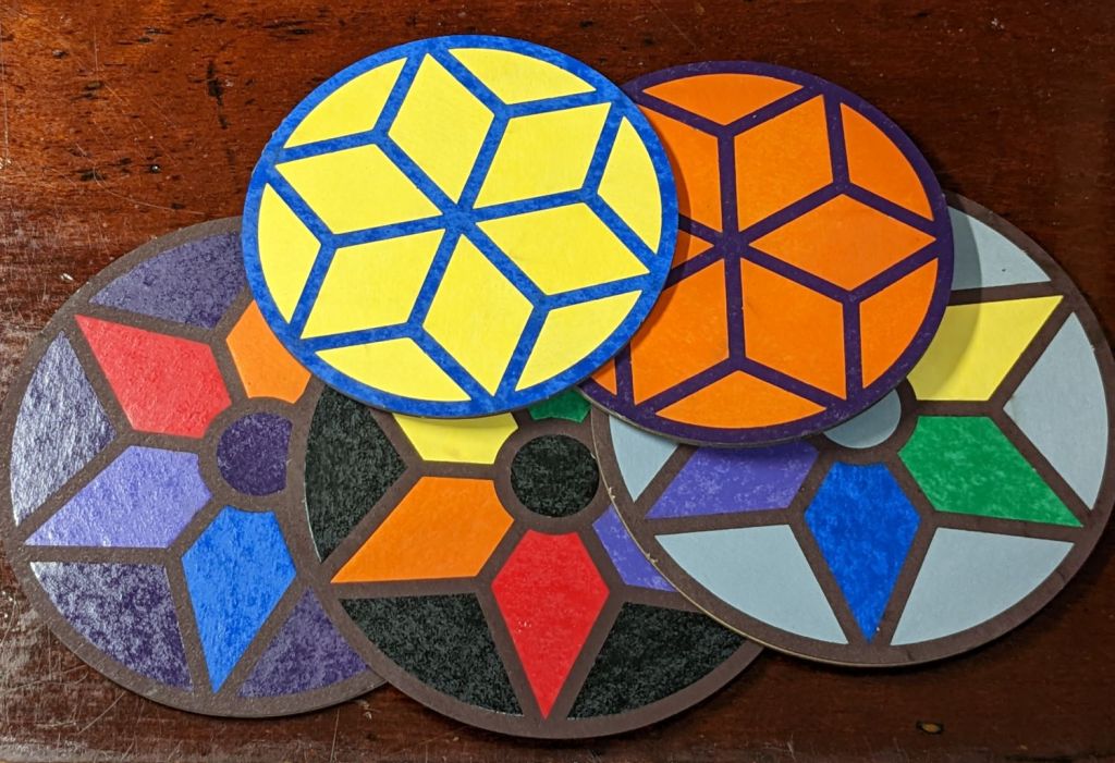
Cut the painted sheets cut face-down atop magnetic spikes on the honeycomb platform, with tabs to keep the petals in place and 0.15 mm kerf compensation. A light touch with an Xacto knife severs the tabs, after which the petals press firmly into the frames. Spread yellow PVA wood glue across the bottom disk, align the perimeters and press together, lay parchment paper between the coasters, clamp the stack between plywood sheets, and they emerge perfectly flat the next day.
They’re too labor-intensive for any economic activity, but I like ’em:
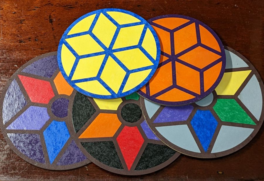
Coaster assortment
The pale gray petals in a white frame looks remarkably like the washed-out color scheme on whatever device you’re reading this, doesn’t it?
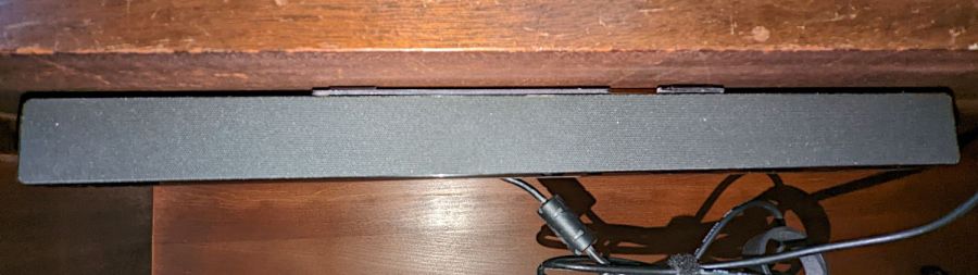
A bedroom rearrangement displaced the Dell Sound Bar attached to the streaming music player from its accustomed perch, so I conjured a mount from the parts bin to hang it from a shelf:
Dell sound bar mount – installed
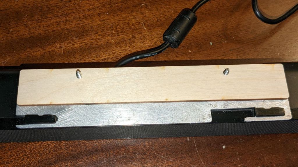
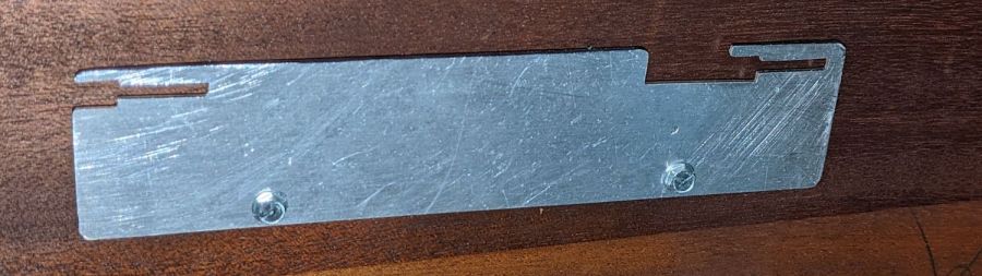
The sound bar originally fit below any Dell monitor with the appropriate lugs under the bezel, but a bit of bandsaw work and hand filing produced a reasonable facsimile from an aluminum sheet:
Dell sound bar mount – plate installed
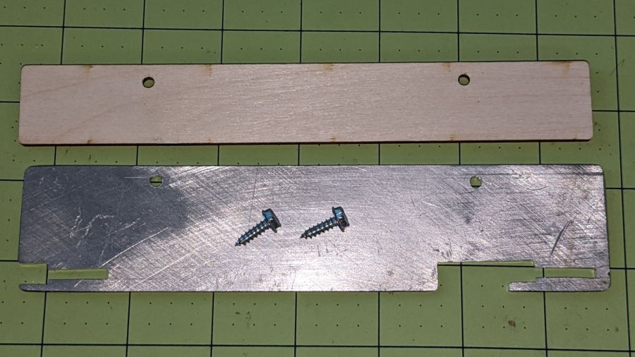
The bar’s plastic bits require a few millimeters of clearance above the sheet, now provided by a matching plywood shape:
Dell sound bar mount – parts
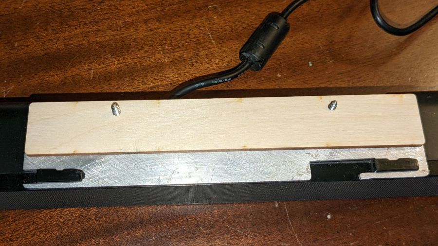
A trial fit showed all the parts would fly in formation:
Dell sound bar mount – trial fit
A laser-cut cardboard template maintained alignment and spacing while I stood on my head screwing the mount in place.
It has a drain hole in the bottom that made this whole thing practical, because a PVC pipe hot-melt-glued atop the drain maintains the water level in the reservoir without any further attention:
Silonn icemaker – drain pipe
The water line from the laser, formerly run directly into the bucket, now goes into the reservoir and through the drain into the bucket. The bucket holds about five gallons of water, with the pump submerged in the bottom.
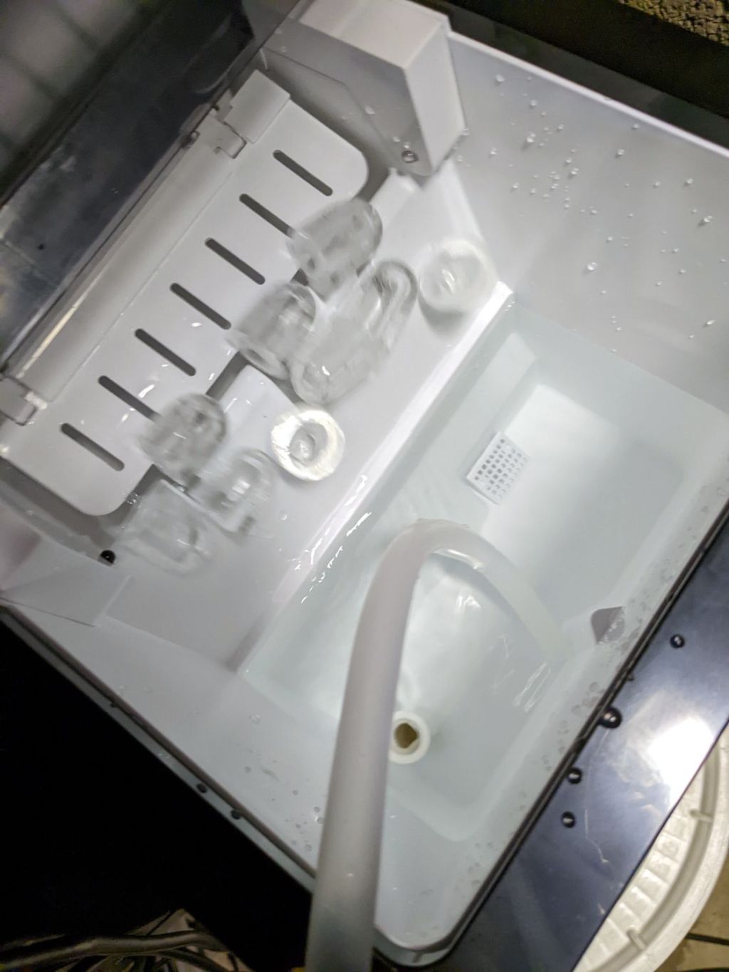
The icemaker pumps water from the reservoir into the little icemaker tray, freezes nine little ice bullets, and scrapes them into the reservoir:
Silonn icemaker – new ice dump
It does that about every eight minutes.
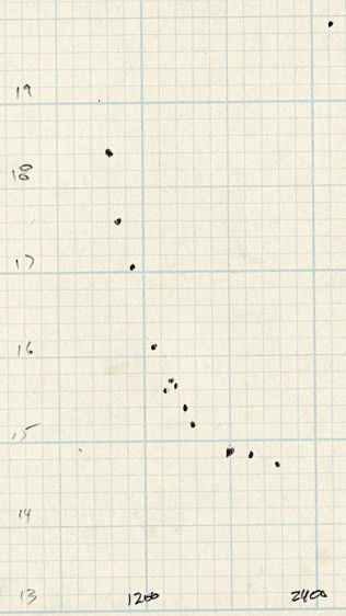
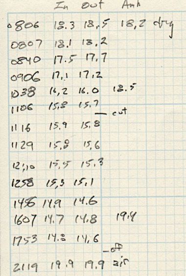
A plot of water temperature vs. time shows what happens:
Silonn icemaker – cooling water plot
It’s as exponential as you could want.
The ice bullets drop into the reservoir and melt there, the cooled water continuously flows into the bucket, and mixes with the rest of the water before being pumped back through the laser. As a result, there are no sudden water temperature changes and the laser remains perfectly happy.
Some numbers for an idea of the cooling capacity:
Freezing 28 pounds = 12.7 kg of ice a day (which, in normal use, would require me to babysit the thing overnight to empty the ice and refill the reservoir) works out to:
12.7 kg × 334 kJ/kg = 4.2 MJ
Spread across 24 hours, that’s 49 W of cooling power. There will be a bit more going into the chilled water surrounding the bullets, but most of the energy goes into the water-to-ice phase change.
Run another way, 5 gallons of water is 42 pounds. The initial cooling slope looks like 2 °C = 3.6 °F in 2 hr, which is 75 BTU/hr = 23 W. However, the water is cooling the laser (which was inert except for one brief cut) as well as the basement, plus (most importantly) there’s a water pump dissipating 20 W submerged in the bucket, so the icemaker is delivering at least 43 W, which is pretty much its rated performance.
It’s obviously incapable of keeping up with a laser doing full-time production work, but for my simple needs it seems better than dunking ice packs in the bucket.
More study (and maybe getting an air-cooled water pump) is in order …
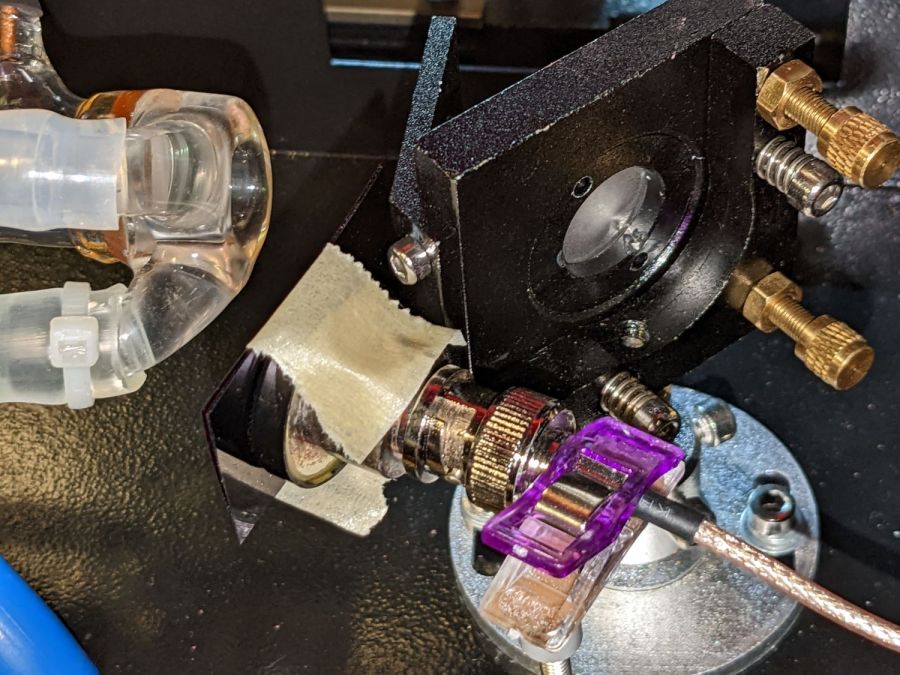
Anything would be better than just taping some gel filters to the front of the bare photodiode package:
Laser output – photodiode kludge
Right?
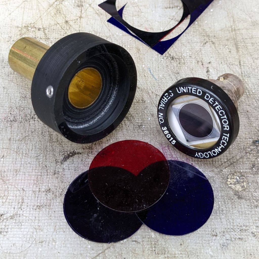
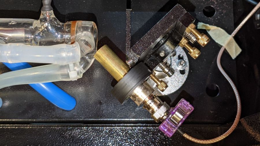
I heaved the slab of ½ inch black acrylic left over from the Totally Featureless (WWVB) Clock into the laser cutter and, two passes at 90% power later, had a somewhat lumpy 32 mm donut with an 11 mm hole in the middle. Because acrylic is opaque to the IR light from a CO₂ laser (which is why it cuts so well) and black acrylic is opaque to visible light (which is what the photodiode is designed for), this is at least as good as an aluminum housing and much easier to make.
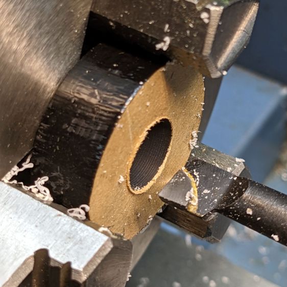
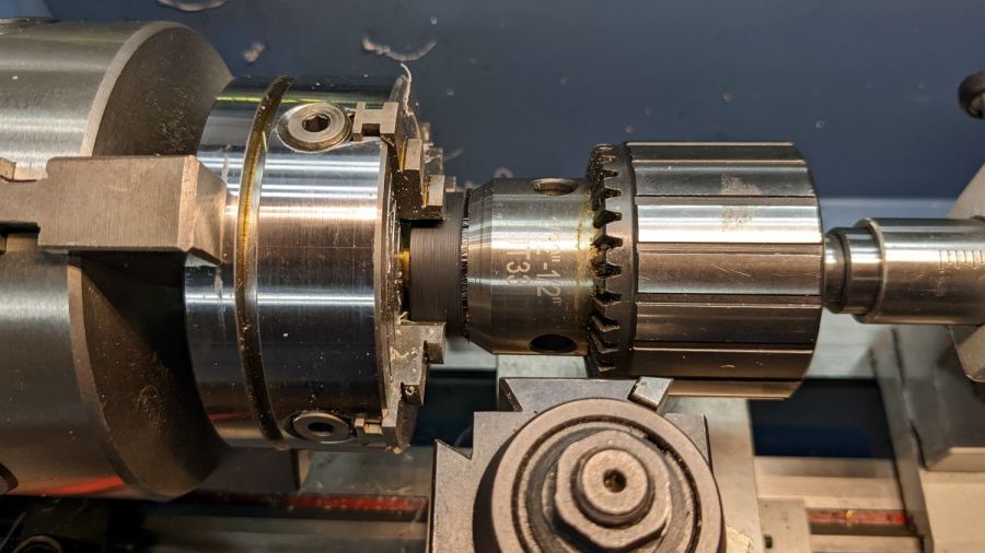
Chuck the donut into Tiny Lathe and bore out the hole:
PIN-10D photodiode filter holder – boring ID
When it’s a snug fit to ½ inch brass tube (about the same size as the photodiode’s active area), flip it around, and bore the other size out to fit the photodiode case.
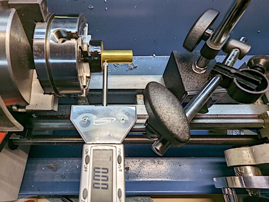
Ram the tube in place, grab the large recess, and center the tube:
[Edit: Got that backwards: I bored the big recess first.]
Skim most of the OD down, then, because I am a dolt forgot to put a spacer in there, flip it around again, get it running true (the chuck aligns the flat side):
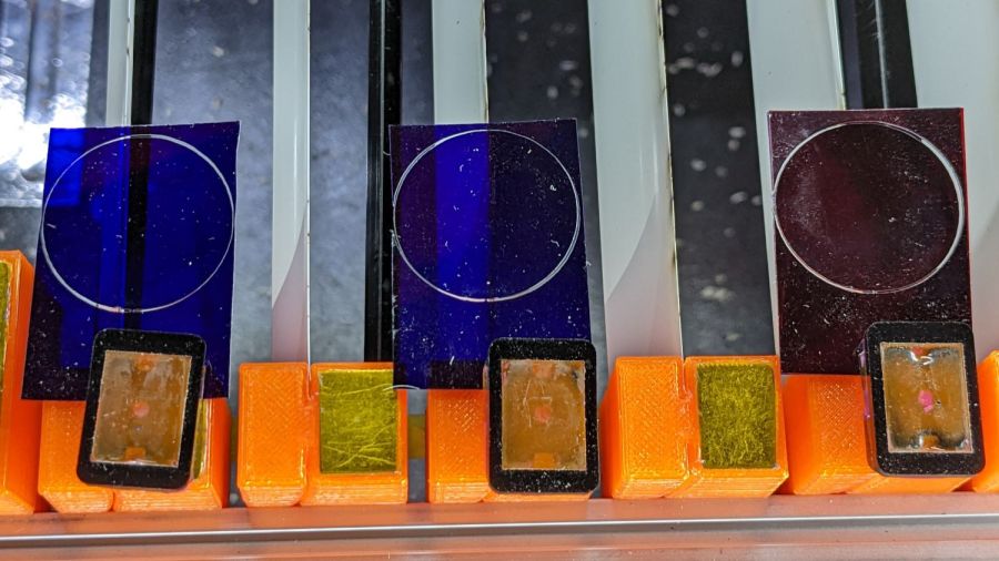
Even though they’re pretty much transparent to thermal IR, a focused IR laser beam cuts them just fine. The little tab at 6 o’clock (remember round clocks with hands?) keeps the cut circle from falling out.
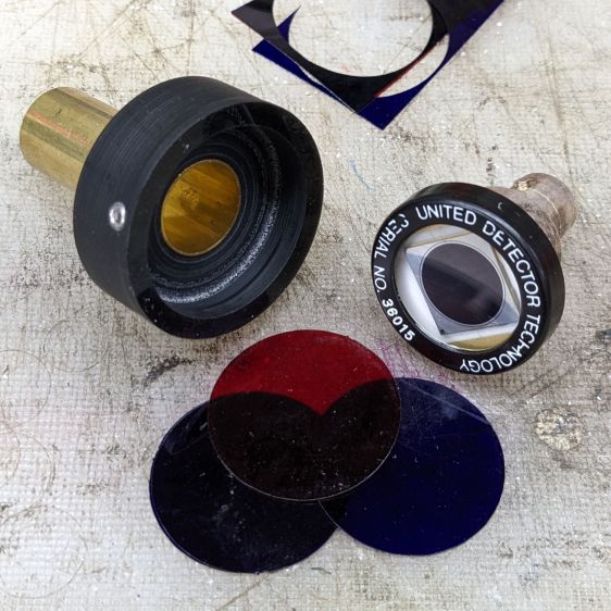
Drill & tap for an M3 setscrew to hold the photodiode in place:
PIN-10D photodiode filter holder – parts
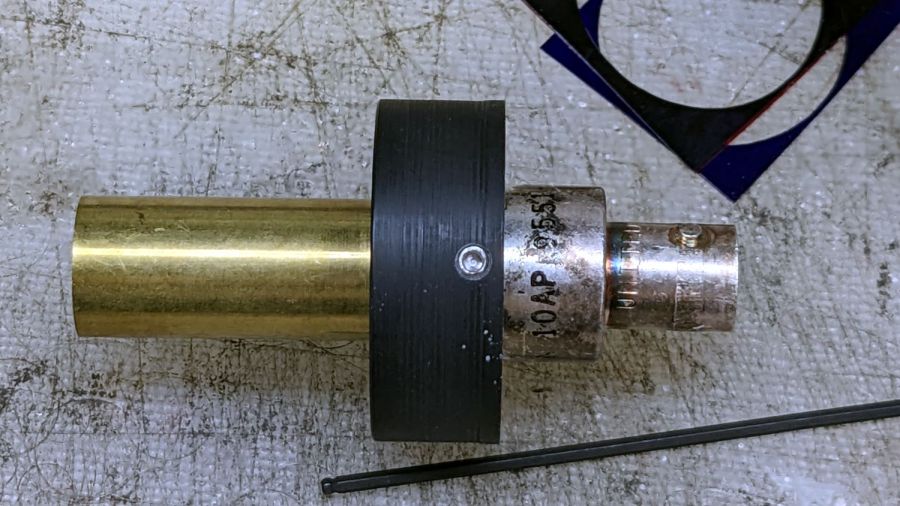
Put them all together:
PIN-10D photodiode filter holder – assembled
I must conjure a better mount for the thing, because this is way too precarious:
PIN-10D photodiode filter holder – test install
Early results suggest it works better than the previous hack job, without ambient light sneaking around the edges of the filter pack.
The test patterns were engraved at various power levels, which was the whole point of the exercise: I was looking at the current waveforms, rather than the acrylic. Despite that, the result should be solid blocks with no speckles in between, which is not quite what happened.
See that isolated spike left of center, where the L-ON signal (magenta trace) is high? That shouldn’t be possible.
Setting the scope to trigger when the L-ON signal is high (= laser power supply disabled) and the tube current is more than a few milliamps (= laser beam active) captures those errant dots.
Sometimes a spurious pulse happens just after L-ON goes high to disable the HV output:
The X axis stepper DIR signal (yellow trace) shows the laser was scanning right-to-left, so the glitch will be just to the left of the 2 mm block in the pattern. In point of fact, it’s about ¾ of the way down the right-hand column:
Engraving Target – stray laser pulses
A closer look shows a distinct circular pit at the end of the line:
Engraving Target – stray laser pulse – detail
The two left-to-right lines bracketing that line also show how the high-intensity pulses affect the laser beam startup intensity during a scan line.
Sometimes the glitches happen quite some time after the laser turns off:
The glitches are not always full-scale events. The two nearly invisible pulses just to the right of the block (bottom green trace) make the smaller dots you can see on the targets:
Tube Current – 20pct – glitch pulses – 10 ma-div
As far as I can tell, spurious dots happen most often with current levels around 20% PWM, less at 10% PWM, and rarely above 30% PWM. I think it has something to do with the chaotic spikes that the power supply produces at lower currents, instead of the relatively stable outputs for higher currents.
The only way to reduce the number of speckles is to use higher power, which will require higher scanning speeds to achieve similar results. Unfortunately, higher speeds give the power supply less settling time, so there may be no good answer.
I haven’t been able to find any “official” schematics for the HV laser power supplies shipped in typical lasers (there are many terminal wiring diagrams), so I have no idea how the L-ON signal controls the output current. Apparently the oscillating chaos inside the power supply occasionally punches through the output switch, which isn’t too surprising given the voltage and power levels in there.