Before trying to make decorative coasters from colorful acrylic, I figured a few practice sessions in chipboard would be in order:

They’re colored with wide tip Sharpies of various ages and, as the yellow and uncolored sections show, chipboard never gets very bright. On the other paw, chipboard is also known as “beer mat”, so at least I have the right general idea.
The patterns come from a GCMC program producing SVG figures for LightBurn to apply kerf compensation:

It’s obviously too late to have me color within the lines.
The overall frame in the upper left and the base plate in the upper right get the kerf compensation, which (for chipboard) turns out to be +0.15 mm outward (thus making the holes smaller and the diameter larger). If I were doing marquetry, I’d want to arrange each piece on a separate wood veneer sheet with proper grain orientation and similar fussiness, but that’s not the point right now.
Without compensation, the pieces have a drop-in fit with an obvious gap:

Adding a mere 0.15 mm on each side produces a very snug fit:

In fact, the pieces go in from the back and require hammering gentle tapping to persuade all the corners into place.
Protip: putting a dark color on the frame and around the edges conceals many flaws.
Increasing the compensation to +0.20 mm means the pieces no longer fit and, when eventually battered into the frame, the surface becomes a concave-upward dish.
With the (colored) pieces in the frame, I covered the base plate with a thin layer of good old Elmer’s Yellow Wood Glue, dropped the top over it with some attention to good alignment on all sides, and clamped the assembly between two planks for a while. Obviously, you’d want to make more than one at a time, but they’re rather labor intensive.
The GCMC program produces the patterns from the coaster’s dimensions:
- Outer diameter
- Number of leaves around the center
- Center spot diameter
- Sash width (it’s really a muntin, but quilters say sash)
- Leaf aspect ratio (max width / overall length)
Due to the relentless symmetry, finding the points describing half a leaf and half the sector between two leaves suffices to generate the entire coaster by various rotations around the center. The code performs no error checking whatsoever, so some dimensions emit a hard crash rather than a coaster.
A geometry doodle with some incorrect values:

Poinr P1 (where the leaf snugs against the circular sash around the center spot) sits at the intersection of a line and a circle, so the code solves a quadratic equation with grisly coefficients:
  a = 1 + pow(tan(LeafStemHA),2);
  b = -2 * tan(LeafStemHA) * (Sash/2) / cos(LeafStemHA);
  c = pow((Sash/2) / cos(LeafStemHA),2) - pow(LeafID/2,2);
  xp = (-b + sqrt(pow(b,2) - 4*a*c))/(2*a);
  xn = (-b - sqrt(pow(b,2) - 4*a*c))/(2*a);
  y = xp*tan(LeafStemHA) - (Sash/2) / cos(LeafStemHA);
  P1 = [xp,y];
Given the geometry, the “plus” root is always the one to use.
A doodle working out that intersection, as well as for P5 out at the widest part of the leaf, carrying some errors from the geometry doodle:
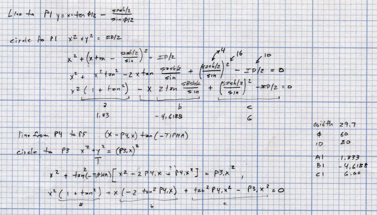
Both of those doodles have errors; the GCMC source code remains the final arbiter of coaster correctness.
The Bash and GCMC source code as a GitHub Gist:
| #!/bin/bash | |
| # Marquetry test piece | |
| # Ed Nisley KE4ZNU – 2022-07-01 | |
| Flags='-P 4 –pedantic' # quote to avoid leading hyphen gotcha | |
| SVGFlags='-P 4 –pedantic –svg –svg-no-movelayer –svg-opacity=1.0 –svg-toolwidth=0.2' | |
| # Set these to match your file layout | |
| ProjPath='/mnt/bulkdata/Project Files/Laser Cutter/Marquetry/Source Code' | |
| LibPath='/opt/gcmc/library' | |
| ScriptPath=$ProjPath | |
| Script='Marquetry Test Piece.gcmc' | |
| leaves="NumLeaves=$1" | |
| aspect="LeafAspect=$2" | |
| fn=Marq-$1-$2.svg | |
| echo Output: $fn | |
| gcmc $SVGFlags -D "$leaves" -D "$aspect" \ | |
| –include "$LibPath" \ | |
| "$ScriptPath"/"$Script" > "$fn" | |
| // Marquetry Laser Cuttery Test Piece | |
| // Ed Nisley KE4ZNU | |
| // 2022-07-01 Simplest possible mandala | |
| layerstack("Frame","Leaves","Rim","Base","Center","Tool1"); // SVG layers map to LightBurn colors | |
| //—– | |
| // Library routines | |
| include("tracepath.inc.gcmc"); | |
| include("tracepath_comp.inc.gcmc"); | |
| include("varcs.inc.gcmc"); | |
| include("engrave.inc.gcmc"); | |
| FALSE = 0; | |
| TRUE = !FALSE; | |
| //—– | |
| // Command line parameters | |
| // -D various useful tidbits | |
| // add unit to speeds and depths: 2000mm / -3.00mm / etc | |
| if (!isdefined("OuterDia")) { | |
| OuterDia = 120.0mm; | |
| } | |
| if (!isdefined("CenterDia")) { | |
| CenterDia = 20.0mm; | |
| } | |
| if (!isdefined("NumLeaves")) { | |
| NumLeaves = 5; | |
| } | |
| if (!isdefined("Sash")) { | |
| Sash = 4.0mm; | |
| } | |
| if (!isdefined("LeafAspect")) { | |
| LeafAspect = 0.40; | |
| } | |
| // Leaf values | |
| LeafStemAngle = 360.0deg/NumLeaves; // subtended by inner sides | |
| LeafStemHA = LeafStemAngle/2; | |
| LeafLength = OuterDia/2 – Sash – (Sash/2)/sin(LeafStemHA); | |
| LeafWidth = LeafAspect*LeafLength; | |
| L1 = (LeafWidth/2)/tan(LeafStemHA); | |
| L2 = LeafLength – L1; | |
| // message("Len: ",LeafLength," L1: ",L1," L2: ",L2); | |
| LeafTipHA = to_deg(atan(LeafWidth/2,L2)); // subtended by outer sides | |
| LeafTipAngle = 2*LeafTipHA; | |
| // message("Width: ",LeafWidth); | |
| // message("Tip HA: ",LeafTipHA); | |
| LeafID = CenterDia + 2*Sash; | |
| LeafOD = LeafID + LeafLength; | |
| // message("ID: ",LeafID," OD: ",LeafOD); | |
| // Find leaf and rim vertices | |
| P0 = [(Sash/2) / sin(LeafStemHA),0.0mm]; | |
| if (P0.x < LeafID/2) { | |
| a = 1 + pow(tan(LeafStemHA),2); | |
| b = -2 * tan(LeafStemHA) * (Sash/2) / cos(LeafStemHA); | |
| c = pow((Sash/2) / cos(LeafStemHA),2) – pow(LeafID/2,2); | |
| // message("a: ",a); | |
| // message("b: ",b); | |
| // message("c: ",c); | |
| xp = (-b + sqrt(pow(b,2) – 4*a*c))/(2*a); | |
| xn = (-b – sqrt(pow(b,2) – 4*a*c))/(2*a); | |
| y = xp*tan(LeafStemHA) – (Sash/2) / cos(LeafStemHA); | |
| // message("p: ",xp," n: ",xn," y: ",y); | |
| P1 = [xp,y]; | |
| } | |
| else { | |
| P1 = P0; | |
| } | |
| P2 = P0 + [L1,LeafWidth/2]; | |
| P3 = P0 + [LeafLength,0mm]; | |
| P4 = P3 + [Sash/sin(LeafTipHA),0.0mm]; | |
| P5r = P4.x * sin(LeafTipHA) / sin(180deg – LeafStemHA – LeafTipHA); | |
| P5 = rotate_xy([P5r,0.0mm],LeafStemHA); | |
| P6 = rotate_xy(P4,LeafStemAngle); | |
| t2 = pow(tan(-LeafTipHA),2); | |
| a = 1 + t2; | |
| b = -2 * t2 * P4.x; | |
| c = t2 * pow(P4.x,2) – pow(P3.x,2); | |
| xp = (-b + sqrt(pow(b,2) – 4*a*c))/(2*a); | |
| xn = (-b – sqrt(pow(b,2) – 4*a*c))/(2*a); | |
| y = (xp – P4.x)*tan(-LeafTipHA); | |
| // message("p: ",xp," n: ",xn," y: ",y); | |
| P4a = [xp,y]; | |
| P6a = rotate_xy(P4a,LeafStemAngle – 2*atan(P4a.y,P4a.x)); | |
| // message("P4a: ",P4a); | |
| // message("P6a: ",P6a); | |
| // message("P0: ",P0); | |
| // message("P1: ",P1); | |
| // message("P2: ",P2); | |
| // message("P3: ",P3); | |
| // message("P4: ",P4); | |
| // message("P5: ",P5); | |
| // message("P6: ",P6); | |
| // Construct paths | |
| LeafPoints = {P1,P2,P3,[P2.x,-P2.y],[P1.x,-P1.y]}; | |
| if (P0 != P1) { | |
| StemArc = varc_ccw(P1 – [P1.x,-P1.y],LeafID/2); | |
| StemArc += [P1.x,-P1.y]; | |
| LeafPoints += StemArc; | |
| } | |
| RimChord = length(P4a – P6a); | |
| RimThick = OuterDia/2 – Sash – length(P5); | |
| RimPoints = {P4a,P5,P6a}; | |
| RimArc = varc_cw(P4a – P6a,P4a.x); | |
| RimArc += P6a; | |
| RimPoints += RimArc; | |
| //— Lay out the frame | |
| linecolor(0xff0000); | |
| layer("Frame"); | |
| goto([CenterDia/2,0mm]); | |
| circle_cw([0mm,0mm]); | |
| repeat(NumLeaves;i) { | |
| a = (i-1)*LeafStemAngle; | |
| tracepath(rotate_xy(LeafPoints,a)); | |
| } | |
| repeat(NumLeaves;i) { | |
| a = (i-1)*LeafStemAngle; | |
| tracepath(rotate_xy(RimPoints,a)); | |
| } | |
| linecolor(0xff0000); | |
| goto([OuterDia/2,0]); | |
| circle_cw([0mm,0mm]); | |
| //— Lay out internal pieces for oriented cutting | |
| // baseplate | |
| layer("Base"); | |
| relocate([OuterDia + 2*Sash,0]); | |
| goto([OuterDia/2,0]); | |
| circle_cw([0mm,0mm]); | |
| // central circle | |
| layer("Center"); | |
| relocate([OuterDia/2 + Sash,-(OuterDia – CenterDia)/2]); | |
| goto([CenterDia/2,0mm]); | |
| circle_cw([0mm,0mm]); | |
| // leaves | |
| layer("Leaves"); | |
| repeat(NumLeaves;i) { | |
| org = [LeafWidth/2 – OuterDia/2,-(OuterDia + Sash)]; | |
| relocate([(i-1)*(LeafWidth + Sash) + org.x,org.y]); | |
| tracepath(rotate_xy(LeafPoints,90deg)); | |
| } | |
| // rim | |
| layer("Rim"); | |
| repeat(NumLeaves;i) { | |
| org = [-Sash,-(OuterDia + 2*Sash + RimChord/2)]; | |
| relocate([(i-1)*(RimThick + Sash) + org.x,org.y]); | |
| tracepath(rotate_xy(RimPoints,180 – LeafStemHA)); | |
| } | |
| // Debugging by printf() | |
| if (FALSE) { | |
| layer("Tool1"); | |
| linecolor(0xff1f00); | |
| goto([Sash/2,0mm]); | |
| circle_cw([0mm,0mm]); | |
| goto(P0); | |
| circle_cw([0mm,0mm]); | |
| goto([0,0]); | |
| move([OuterDia/2,0]); | |
| goto([0,0]); | |
| move(OuterDia/2 * [cos(LeafStemHA),sin(LeafStemHA)]); | |
| goto(P2); | |
| move_r([0,-LeafWidth/2]); | |
| } |

Comments
7 responses to “Laser Kerf Width Test Pattern / Coaster Generator”
There must be fractals…
“Fractal Analysis of Jackson Pollock’s Poured Paintings”
https://blogs.uoregon.edu/richardtaylor/2016/02/08/fractal-analysis-of-jackson-pollocks-poured-paintings/
Nah, it’s all 2D, maybe 2-½D if you’re being generous, surely no more.
Nary a Moebius strip in sight!
[…] figured out how to intersect a line with a circle, I figured I could do it twice to put arcs on both the inside and the outside of each […]
[…] I’m getting better about fitting laser-cut pieces into frames, it occurred to me that mashing colored epoxy together with coaster-shaped scrap acrylic might be […]
[…] written some parametric coaster generators, I did this for a Digital Machinist […]
[…] manually with LightBurn’s Offset tool: shrink the frame’s interior openings (which lie outside the frame) by 1 mm per step, then cut each shape into a different […]
[…] middle one comes from a version of the original GCMC marquetry shape generator, tweaked to produce just the frame SVG, called by a Bash script to change the sash width, and […]