While I had the hatch open, I thought it would be interesting to look at the HV supply’s current waveforms:
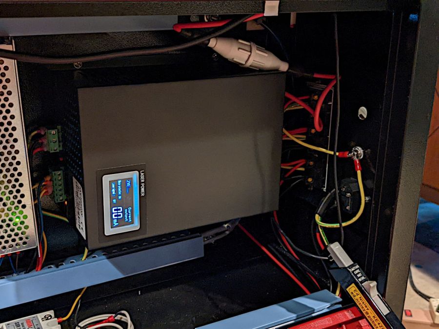
The Tek current probe over on the right measures return current through the cathode wire, the point in the circuit where you might be tempted to install an ordinary analog (moving-coil) panel milliammeter, oriented so (conventional) current returning from the tube will produce a positive voltage.
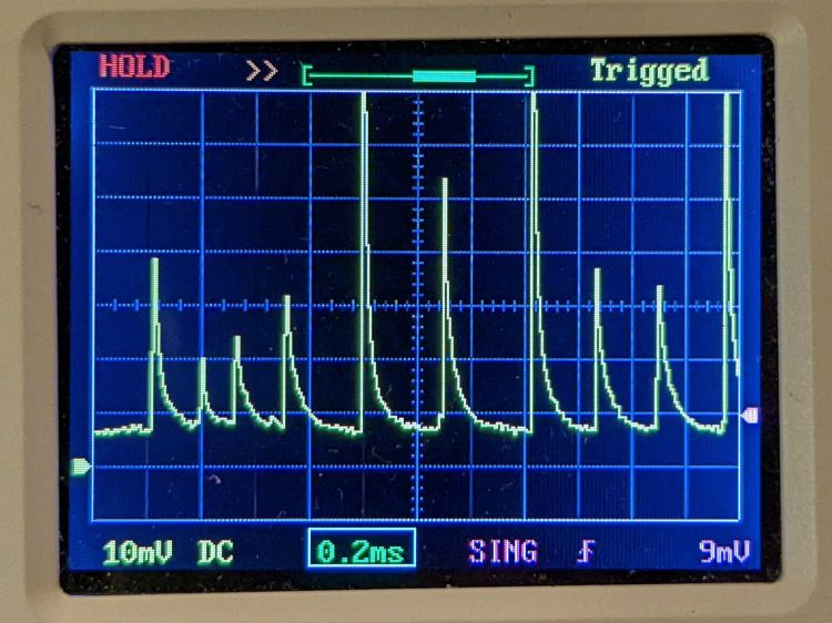
Unfortunately, an analog meter isn’t up to displaying anything meaningful for this nonsense:

Admittedly, that’s a 50 ms pulse, during which an analog meter would barely twitch. The vertical scale is 5 mA/div, so the highest peaks exceed 35 mA, more than twice the tube’s recommended “14-15 mA”.
A closer look at the pulse startup waveform:
It sure looks like the chaotic current through a forced neon-bulb relaxation oscillator. Remember neon bulbs?
An even closer look:
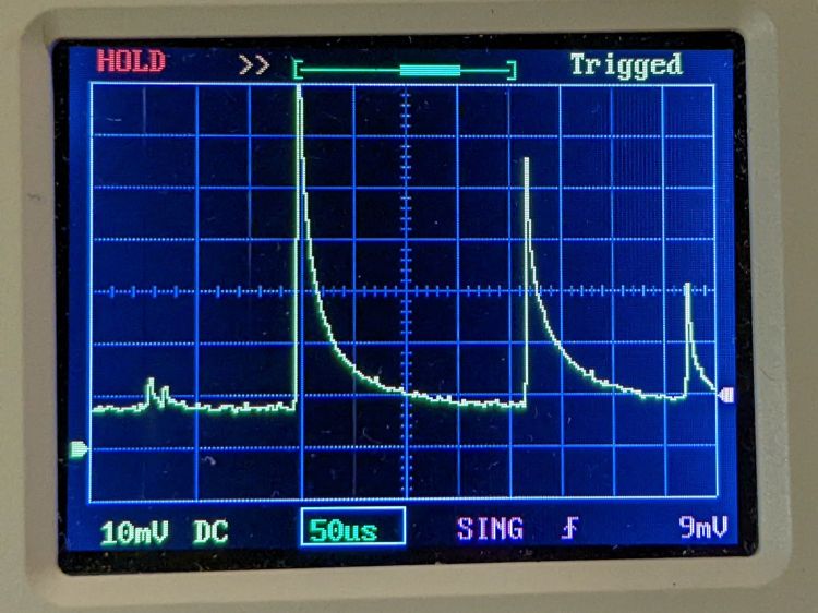
That’s at 10% PWM, close to the threshold below which the laser just won’t fire at all. The power supply must ramp up to produce enough voltage to fire the tube while simultaneously limiting the current to prevent the discharge from sliding down the negative resistance part of its curve.
Apparently this supply isn’t quite up to the task.
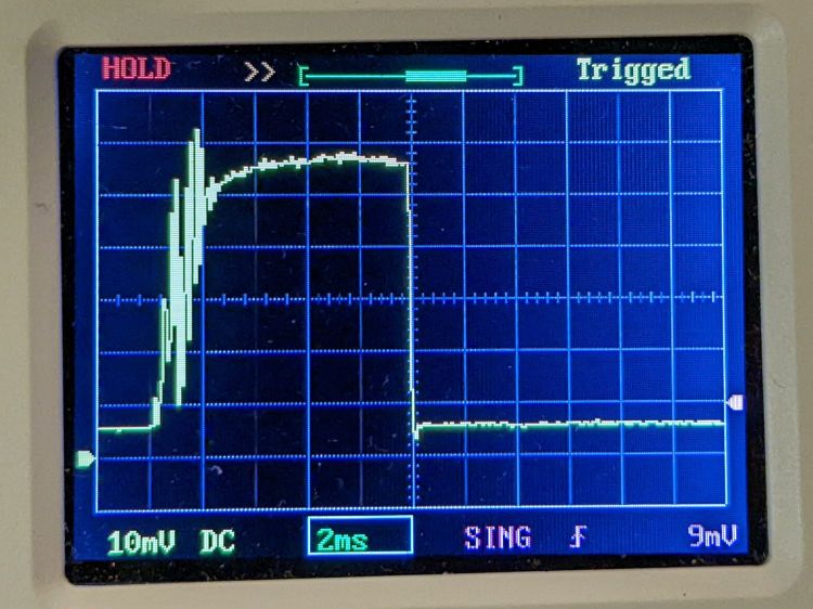
A 10 ms pulse at 50% PWM gives the supply enough time to stabilize the current:
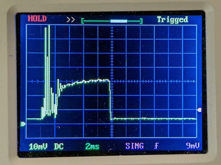
The 14-ish mA at the tail end of the pulse (note the baseline offset) matches my previous 13 to 14 mA measurements as closely as seems reasonable. That 2 ms of hash on the leading edge suggests the start of each cut or engraving line will be a bit darker than you might expect.
Another 10 ms pulse, this time at 99% PWM:
The peak 24-ish mA matches the previous measurements. Note that the peaks in all the previous pictures exceed the 99% PWM current level.
AFAICT, all PWM values below about 25% produce equivalent results: random current spikes with unpredictable timing and amplitude. Changing the PWM value does not affect the (average) tube current or laser output power in any predictable way.
Some samples to illustrate the point, starting with a different 50 ms pulse at 10% PWM than the first one up above:
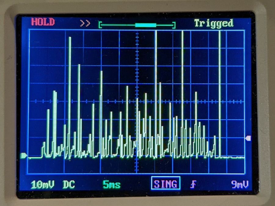
A 50 ms pulse at 15% PWM:
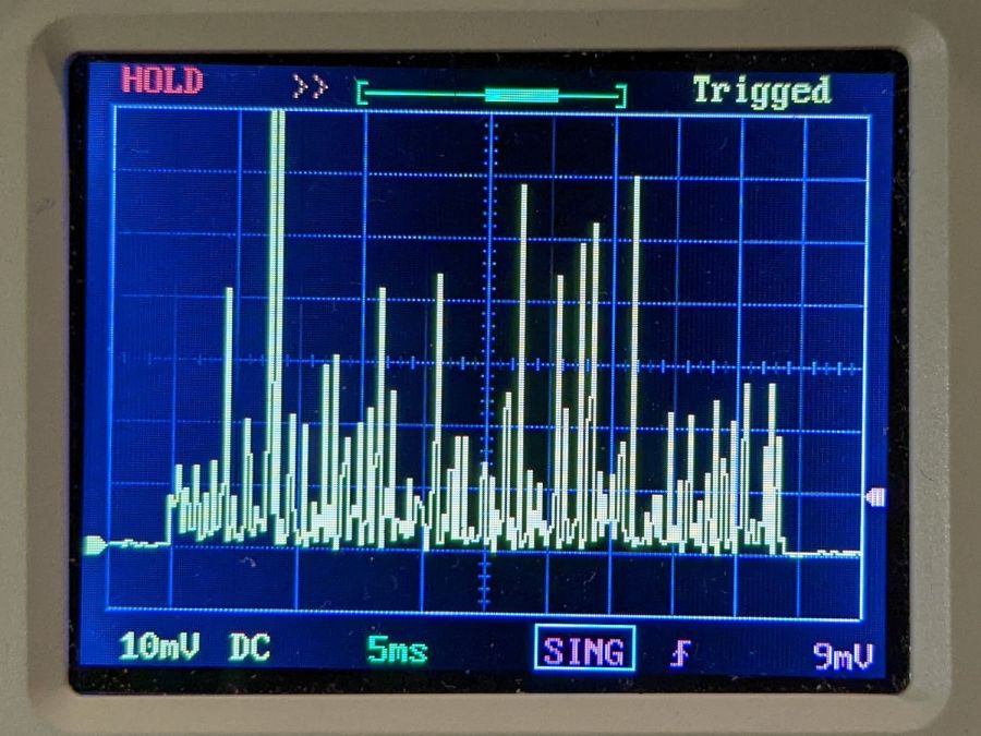
A 50 ms pulse at 20% PWM:

A 50 ms pulse at 25% PWM:
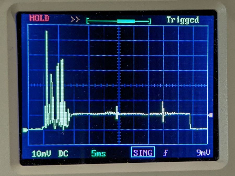
Now, that last one is different. After the hash during the first 8 ms or so, the power supply actually produces a stable 5 mA beam current, which is roughly what I measured using the power supply’s meter.
However, the other three are pretty much identical: the 10% PWM pulse does not delivers half as energy as the 20% PWM pulse. The waveforms may be different, but not in a meaningful or consistent way: the two 50 ms 10% pulses are different, but you’d (well, I’d) have trouble separating them from the 20% pulse.
To summarize:
- The first several millisconds of any pulse will consist of randomly distributed spikes with very large tube currents.
- For PWM values greater than 25%, the tube current will settle down to the corresponding current after 5 to 10 ms. Before the current settles down, the tube will be firing those random spikes.
- For PWM values less than 25%, the tube current never settles down: the entire pulse, no matter how long, will be short, high-intensity spikes, without a consistent DC-ish level.
No matter what an analog meter might show.
I have no way to know if this power supply is defective, but I’ll certainly ask …

Comments
3 responses to “OMTech 60 W Laser: Replacement HV Power Supply Waveforms”
[…] seen some rather bizarre laser tube current waveforms from the replacement power supply (and an equivalent Cloudray supply I bought as a backup) in the […]
[…] these measurements are for the replacement HV supply I got when the original supply failed, I saw similar chaotic waveforms with a Cloudray HV supply I bought as a backup. Given that other people have reported similar random dots with many other […]
[…] have no spec sheet for the replacement power supply OMTech sent, which is now installed in the laser and is measured below. I believe all similar HV […]