If you regard your new CNC 3018-Pro Router kit as a box of parts which could, with some adjustments and additional parts, become a small CNC router, you’re on the right track.
In my case, the aluminum extrusions arrived somewhat squashed inside their well-padded foam shipping carton, which leads me to believe the factory responsible for tapping the bolt holes in the ends must be a fairly nasty place. In any event, the hammerhead T-nuts for the gantry struts simply didn’t fit into some sections of the slots, although they worked fine elsewhere.
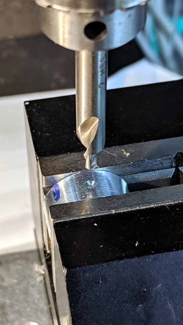
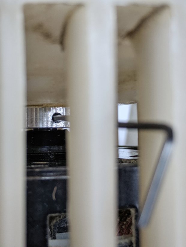
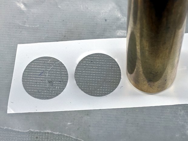
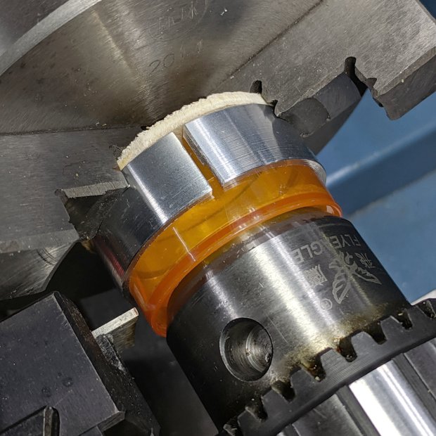
So, file a smidge off the rounded sides of a few nuts:
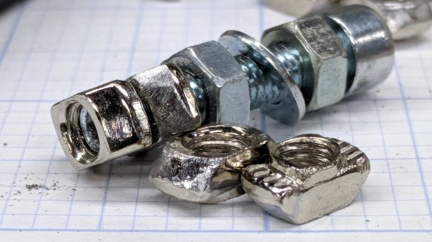
Which let them slide into place and rotate properly despite the bent channel:

The assembly instructions used a word I’d never encountered before:

Turns out ubiety is exactly correct, but … raise your hand if you’ve ever heard it in polite conversation. Thought so.
I’ve not noticed any harm from rounding off the position to 46 mm; just position both struts the same distance from the rear crossbar and it’s all good.
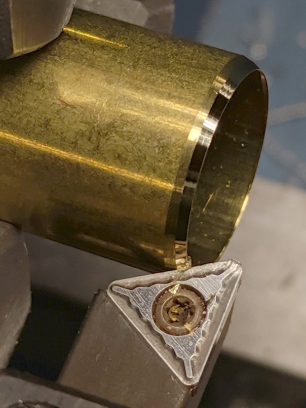
The struts behind the CAMTool CNC-V3.3 electronics board were also squashed, prompting a bit more filing:

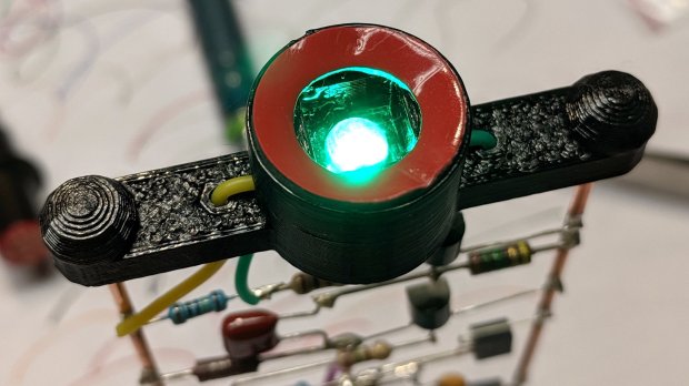
The CAMTool board is basically an Arduino-class microcontroller preloaded with GRBL 1.1f and surrounded with spindle / stepper driver circuits.
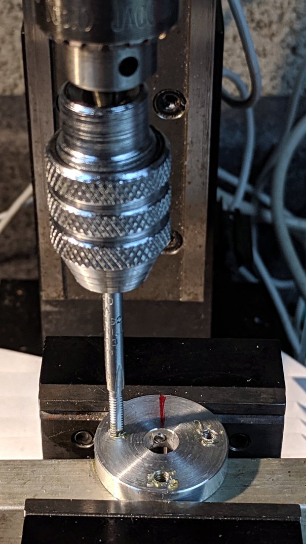
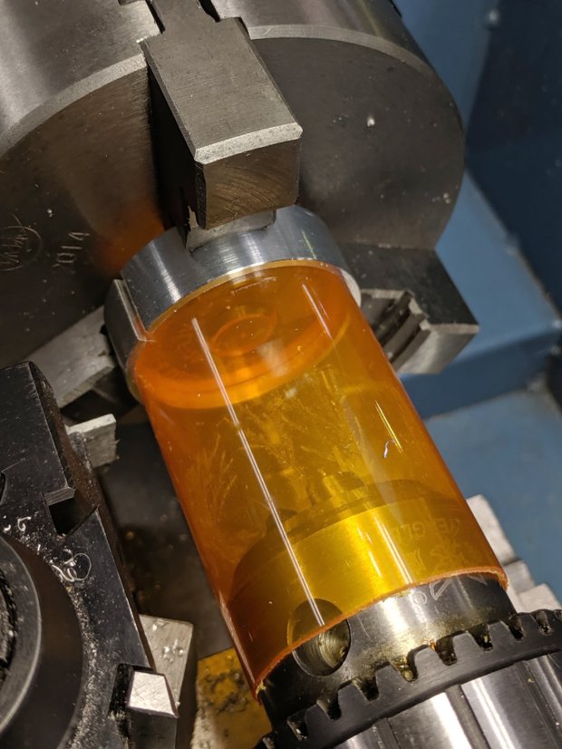
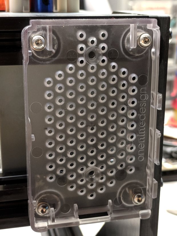
As with the MPCNC, I’ll dribble G-Code into it from a Raspberry Pi. Alas, the struts behind the CAMTool board are on 75 mm centers, but the Pi cases on hand have feet on 72-ish mm centers. Pay no attention to the surroundings, just drill the holes in the right spots:

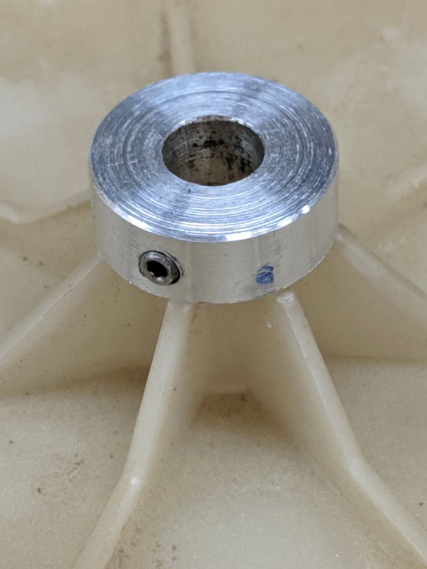
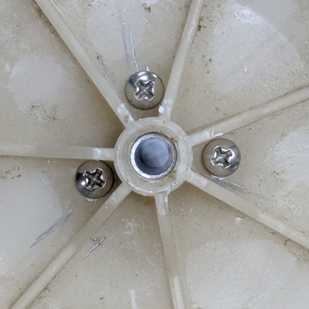
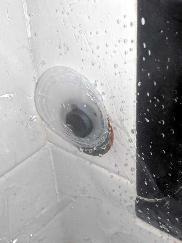
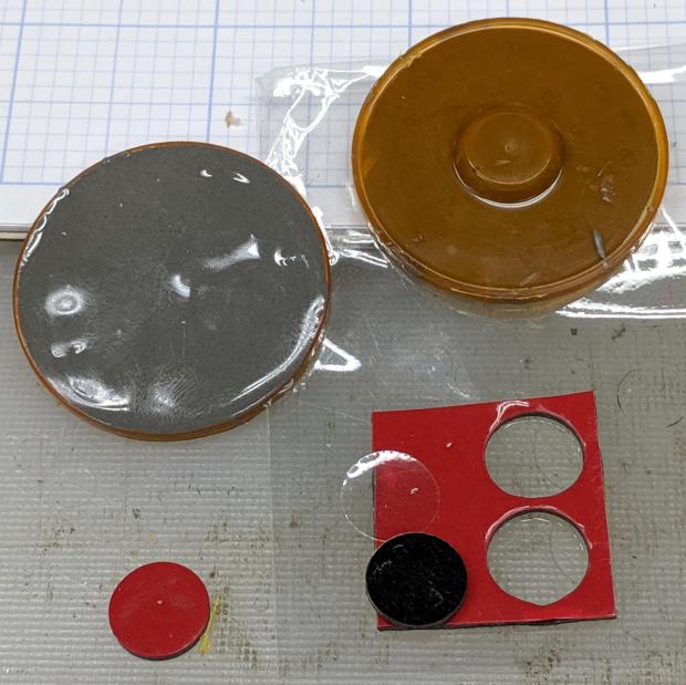
Add more T-nuts and short button head screws, with rubber pads between the case and the struts:
It’s coming together!