Ed Nisley's Blog: Shop notes, electronics, firmware, machinery, 3D printing, laser cuttery, and curiosities. Contents: 100% human thinking, 0% AI slop.
Tag: Improvements
Making the world a better place, one piece at a time
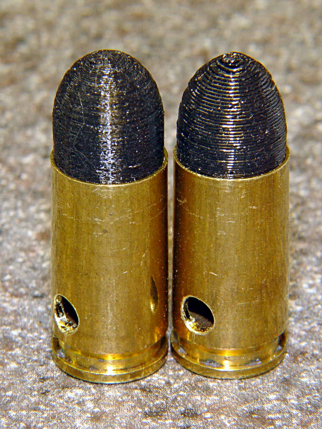
As you might expect, changing the layer thickness to 0.1 mm = 100 μm dramatically improves the appearance of the dummy 9 mm Luger bullet on the left, compared to the 0.25 mm = 250 μm layers on the right:
Dummy 9 mm Luger cartridges – 0.1 mm layer – overview
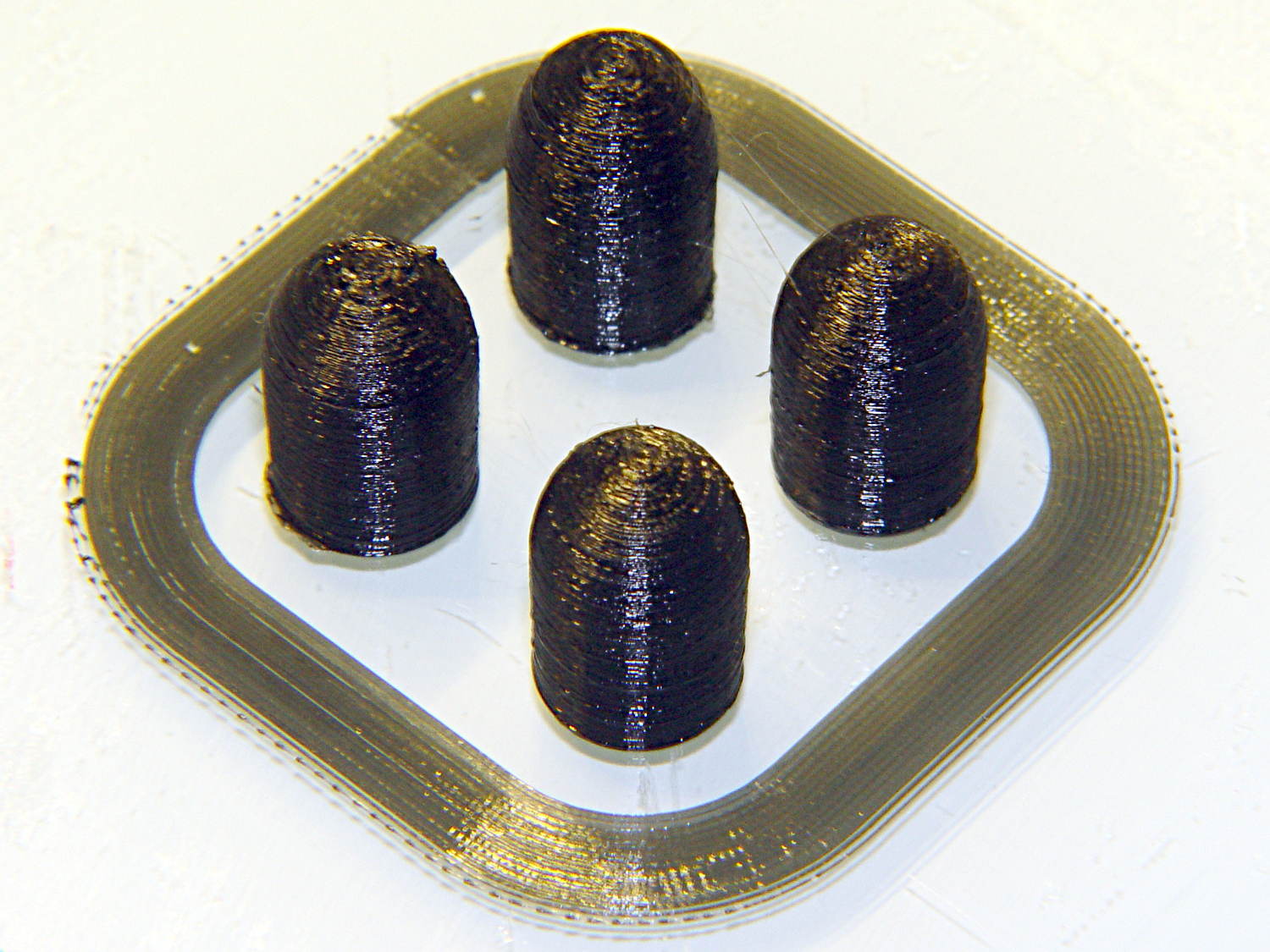
The inside edge of the translucent skirt around the quartet measured 90 to 110 μm, so the layer height is spot on:
Dummy 9 mm Luger bullets – 0.1 mm layer – overhead on platform
That required no adjustments to the M2 at all; It Just Works. Admittedly, that’s with a custom platform and firm supports replacing the springs, plus better Z-axis homing, but the overall structure was fine to start with.
I used the same Slic3r settings as before, with the only change being the layer thickness. Letting it pick the layer width might produce better results, but a 0.35 mm nozzle won’t go much narrower than 0.40 mm anyway.
A closer look at the bullet show the thinner layers provide a better rendition of the stretched sphere forming the nose; it’s less pointy than the one assembled from thicker layers:
Dummy 9 mm Luger bullets – 0.1 mm layer – side
The nose closes better with thinner layers:
Dummy 9 mm Luger bullets – 0.1 mm layer – nose
None of that really matters for this application, but it’s a useful data point.
The downside is that printing with thinner layers requires more time: a single bullet (of 16) requires 2.2 minutes at 250 μm and (of 4) 9 minutes at 100 μm. The simple ratio of layer thicknesses predicts a factor of 2.5, not 4, but the skirt requires a larger fraction of the total time. The estimated time for a 4×4 array at 100 μm comes out at 5.2 minutes each, a factor of 2.4, which is close enough.
Although 100 μm certainly looks better, it doesn’t really improve anything for most of the blocky stuff I make…
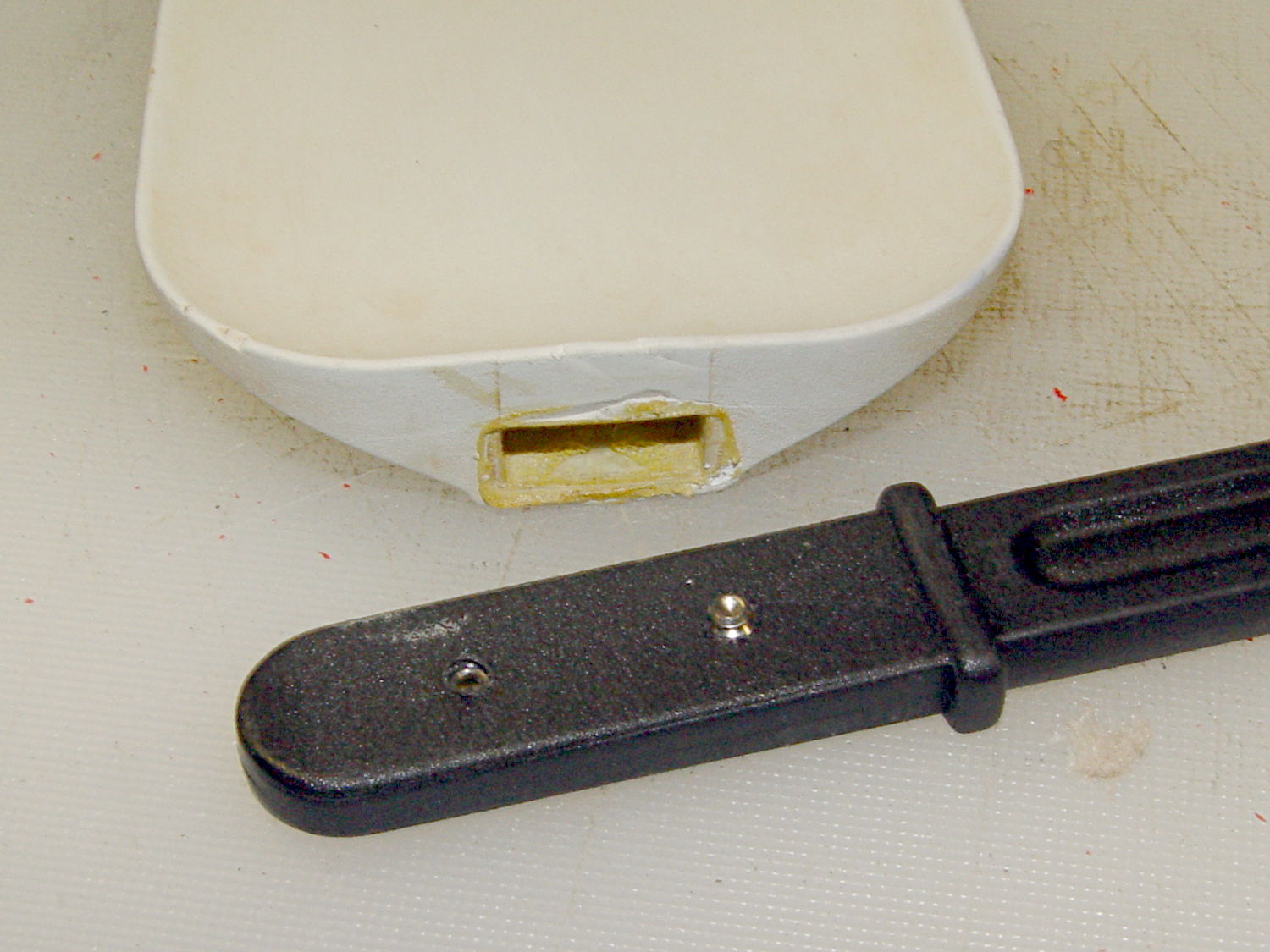
Shortly after we bought this kitchen scraper spatula (or whatever it’s called), the handle pulled out of the blade and left it sitting in a bowl of batter. That turned out to be unsurprising, given that neither side of the interface has any mechanical locking features. I rinsed the batter off, stuck some urethane glue inside, rammed the handle in place, and hoped for the best. Lacking any mechanical interlock and not bonding to either surface, the adhesive didn’t improve the situation.
So I recently added a pair of stainless 4-40 setscrews standing just proud of the handle’s surface that should dig into the blade and hold it in place:
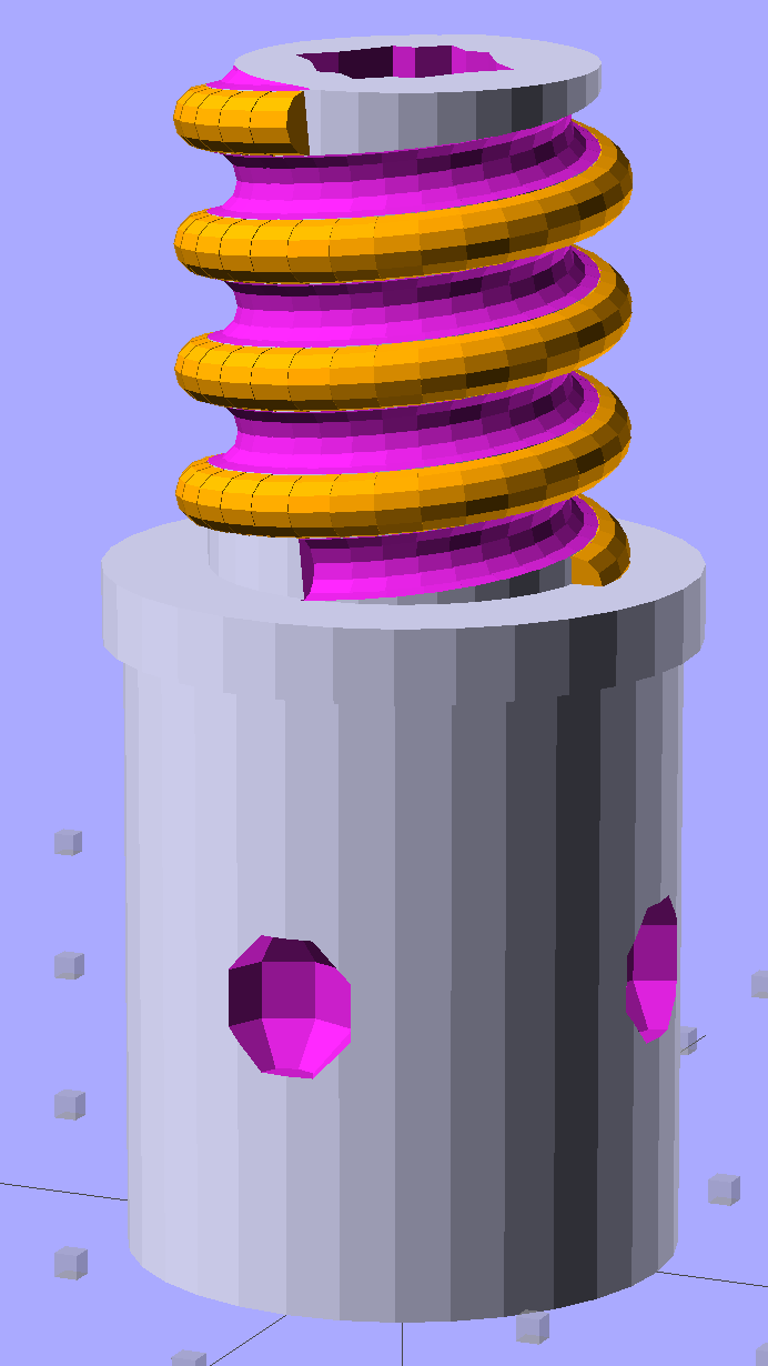
Although the current OpenSCAD could produce a solid model with the screw thread’s dedendum, I’d never actually printed one of them:
Broom Handle Screw – full thread – solid model
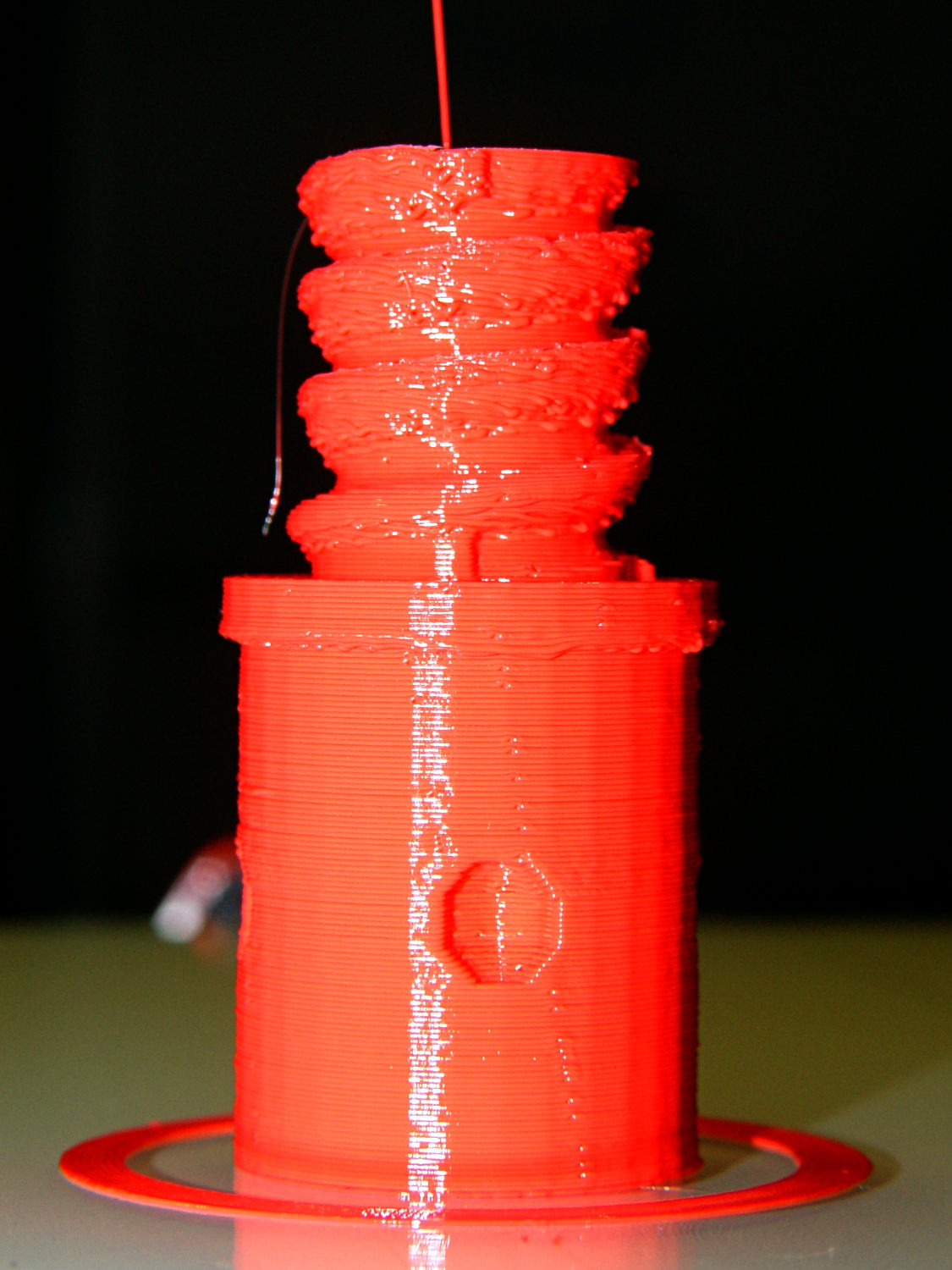
I need some fondlestuff illustrating how to handle overhangs, so I ran one standing vertically, which (pretty much as I expected) didn’t work well at all:
Broom Handle Screw – dedendum – vertical
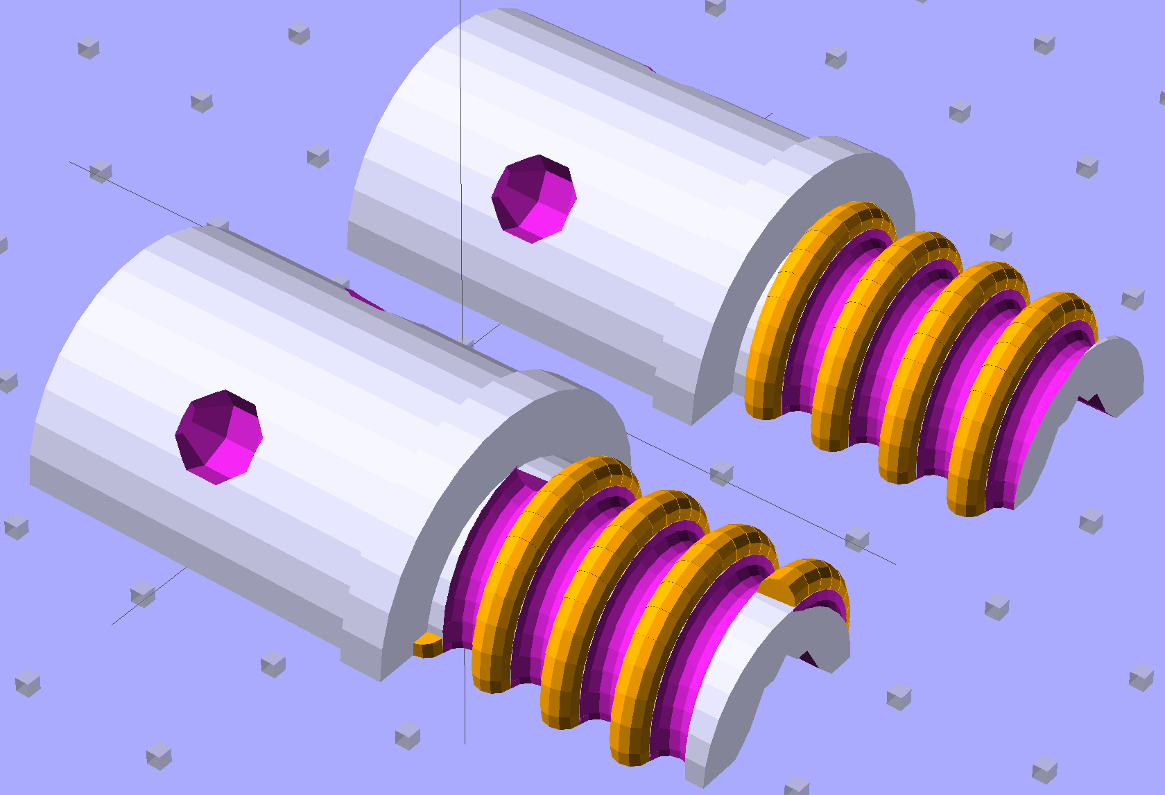
The trick is to split the model down the middle:
Broom Handle Screw – horizontal top
And put holes in each half for alignment pins:
Broom Handle Screw – horizontal bottom
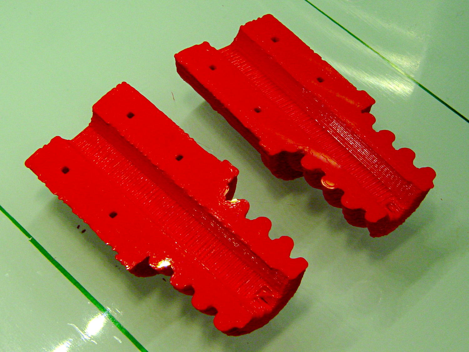
Then you can print it lying down:
Broom Handle Screw – horizontal – as-printed top
The internal overhang would probably call for some support material, particularly in the square recess at the end, but in this case it’s a lesson:
Glue some filament snippets into the holes, snap it together, and it looks just fine over there on the right:
Broom Handle Screw – orientation comparison
Doesn’t matter how many I print, it still doesn’t make any economic sense as a broom repair…
The OpenSCAD source code now has a Layout variable to control the orientation and, not as shown in the model, the alignment pins have glue gutters in the first layer:
// Broom Handle Screw End Plug
// Ed Nisley KE4ZNU October 2013

Layout = "Horizontal";		// Vertical Horizontal Pin

UseDedendum = true;			// true to create full thread form

//- Extrusion parameters must match reality!

ThreadThick = 0.25;
ThreadWidth = 0.40;

HoleWindage = 0.2;

Protrusion = 0.1;			// make holes end cleanly

//----------------------
// Dimensions

PostOD = 22.3;				// post inside metal handle
PostLength = 25.0;

FlangeOD = 24.0;			// stop flange
FlangeLength = 3.0;

PitchDia = 15.5;			// thread center diameter
ScrewLength = 20.0;

ThreadFormOD = 2.5;			// diameter of thread form
ThreadPitch = 5.0;
NumSegments = 32;			//  .. number of cylinder approximations per turn

BoltOD = 7.0;				// clears 1/4-20 bolt
BoltSquare = 6.5;			// across flats
BoltHeadThick = 3.0;

RecessDia = 6.0;			// recesss to secure post in handle

OALength = PostLength + FlangeLength + ScrewLength;

SplitOC = 1.25*FlangeOD;	// separation in Horizontal layout
PinOD = 1.75;				// alignment pin diameter = filament stub
PinLength = 7.0;			//  ... length

$fn=8*4;					// default cylinder sides

echo("Pitch dia: ",PitchDia);
echo("Root dia: ",PitchDia - ThreadFormOD);
echo("Crest dia: ",PitchDia + ThreadFormOD);

Pi = 3.14159265358979;

//----------------------
// Useful routines

// Wrap cylindrical thread segments around larger plug cylinder

module CylinderThread(Pitch,Length,PitchDia,ThreadOD,PerTurn) {

CylFudge = 1.02;				// force overlap

    RotIncr = 1/PerTurn;
    PitchRad = PitchDia/2;

    Turns = Length/Pitch;
    NumCyls = Turns*PerTurn;

    ZStep = Pitch / PerTurn;

    HelixAngle = atan(Pitch/(Pi*PitchDia));
    CylLength = CylFudge * (Pi*(PitchDia + ThreadOD) / PerTurn) / cos(HelixAngle);

	for (i = [0:NumCyls-1]) {
		assign(Angle = 360*i/PerTurn)
			translate([PitchRad*cos(Angle),PitchRad*sin(Angle),i*ZStep])
				rotate([90+HelixAngle,0,Angle])
					cylinder(r1=ThreadOD/2,
							r2=ThreadOD/(2*CylFudge),
							h=CylLength,
							center=true,$fn=12);
	}
}

// Build complete plug

module ScrewPlug() {
	difference() {
		union() {
			cylinder(r=PostOD/2,h=PostLength);
			cylinder(r=PitchDia/2,h=OALength);
			translate([0,0,PostLength])
				cylinder(r=FlangeOD/2,h=FlangeLength);
			color("Orange")
			translate([0,0,(PostLength + FlangeLength)])
				CylinderThread(ThreadPitch,(ScrewLength - ThreadFormOD/2),PitchDia,ThreadFormOD,NumSegments);
		}

		translate([0,0,-Protrusion])
			PolyCyl(BoltOD,(OALength + 2*Protrusion),6);

		translate([0,0,(OALength - BoltHeadThick)])
			PolyCyl(BoltSquare,(BoltHeadThick + Protrusion),4);

		if (UseDedendum)
			translate([0,0,(PostLength + FlangeLength + ThreadFormOD/2 - ThreadPitch/(2*NumSegments))])
				rotate(-90 - 360/(2*NumSegments))
				CylinderThread(ThreadPitch,ScrewLength,PitchDia,ThreadFormOD,NumSegments);

		for (i = [0:90:270]) {
			rotate(45 + i)					// 45 works better with Horizontal layout
				translate([PostOD/2,0,PostLength/2])
					sphere(r=RecessDia/2,$fn=8);
		}
	}
}

// Locating pin hole with glue recess

module LocatingPin() {

	translate([0,0,-ThreadThick])
		PolyCyl((PinOD + 2*ThreadWidth),2*ThreadThick,4);
	translate([0,0,-(PinLength/2 + ThreadThick)])
		PolyCyl(PinOD,(PinLength + 2*ThreadThick),4);

}

module PolyCyl(Dia,Height,ForceSides=0) {			// based on nophead's polyholes

  Sides = (ForceSides != 0) ? ForceSides : (ceil(Dia) + 2);

  FixDia = Dia / cos(180/Sides);

  cylinder(r=(FixDia + HoleWindage)/2,
           h=Height,
	   $fn=Sides);
}

module ShowPegGrid(Space = 10.0,Size = 1.0) {

  Range = floor(50 / Space);

	for (x=[-Range:Range])
	  for (y=[-Range:Range])
		translate([x*Space,y*Space,Size/2])
		  %cube(Size,center=true);

}

//-------------------
// Build it...

ShowPegGrid();

if (Layout == "Vertical")
	ScrewPlug();

if (Layout == "Pin")
	LocatingPin();

if (Layout == "Horizontal")
	for (i=[-1,1])
		difference() {
			translate([i*SplitOC/2,PostLength/2,0])
				rotate([90,180*(i + 1)/2,0])
					ScrewPlug();

			translate([0,0,-FlangeOD/2])
				cube([2*OALength,2*OALength,FlangeOD],center=true);

			for (j=[-1,1], pin=[-1,1])
				assign(PinX = i*SplitOC/2 + pin*(PostOD + BoltOD)/4,
					   PinY = j*PostLength/4) {
					translate([PinX,PinY,0])
						rotate(45)
							LocatingPin();
					echo("i j pin: ",i,j,pin);
					echo("X Y: ",PinX,PinY);
				}
		}
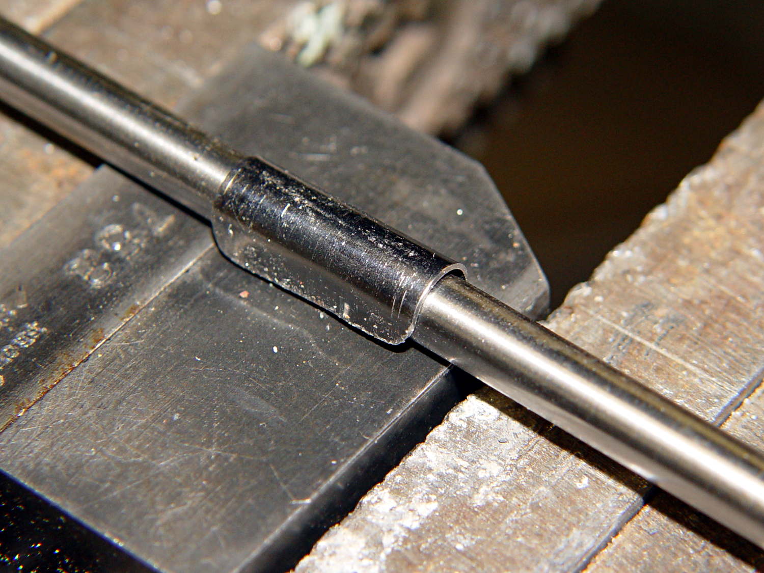
A few trips with the M2 convinced me that the cable to the relocated Z-min switch along the front of the X gantry needed a clip on each end and should not run under the gantry. This time I used the full width of the steel strap and bashed a neater curve around a length of drill rod:
M2 Z-min Cable Clip – forming
The new clips look a bit better with straight edges:
M2 Z-min Cable Clips – old vs new
The top view shows the new clips and cable location:
M2 Z-min Switch – top view
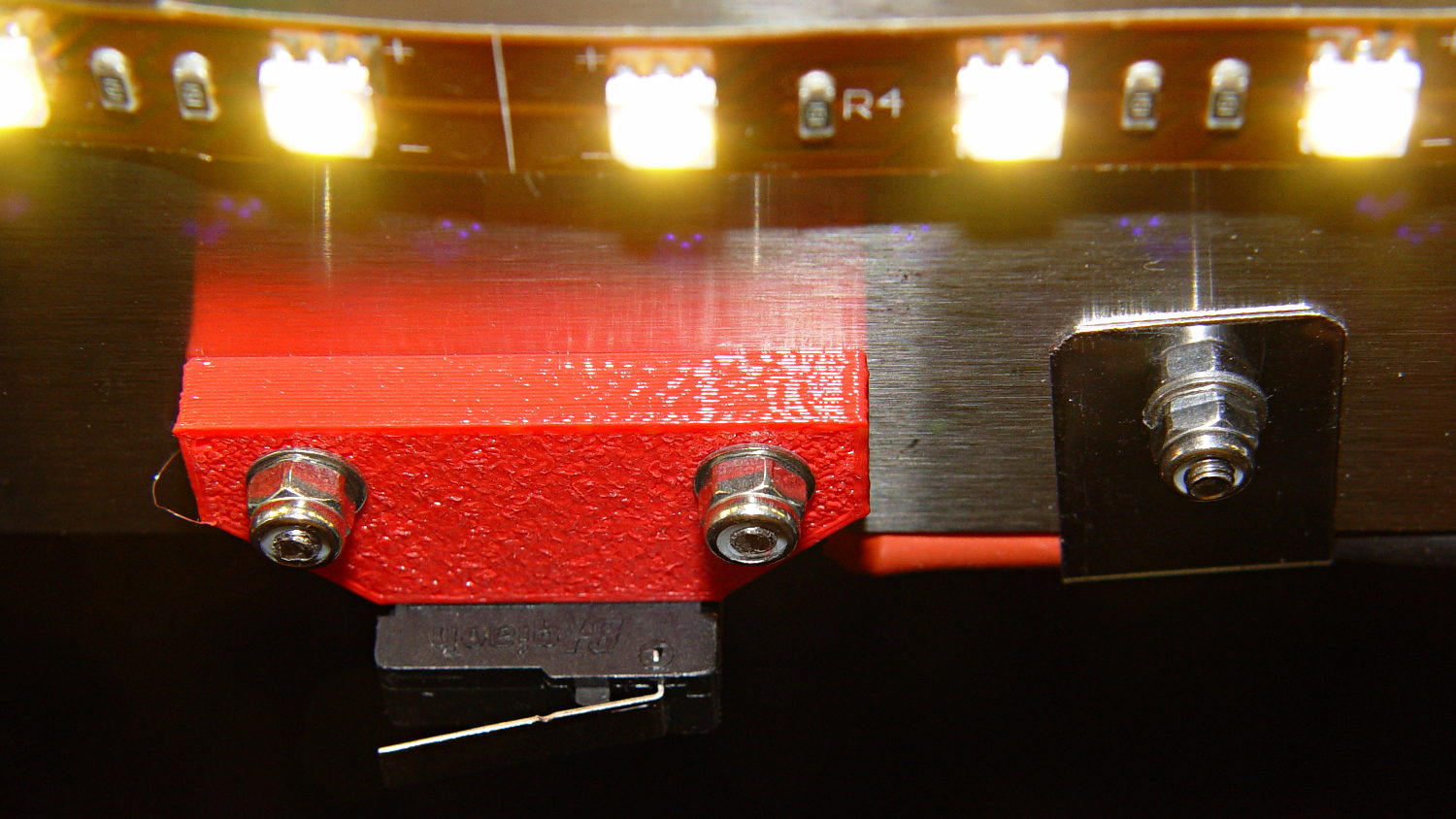
While I was at it, I trimmed the edges off the switch mounting block. Rather than figure out the trig required to hack off the corners, I applied linear_extrude() to a polygon() defined by some obvious points, then poked the same holes in the block:
Z-min Front Mount Switch Block – chamfer – solid model
It pretty much vanishes in the top view, but here’s a view from the +Y end of the platform:
M2 Z-min Switch – bottom view
Despite all that maneuvering, the G92 Z-4.55 touchoff value remained the same!
If you’ve forgotten why all this makes sense, it’s a first pass at detecting the actual build platform position. The stock M2 uses that switch to detect the top of a screw attached to the Z-axis stage, which means it can’t sense the actual platform. The Z-min switch I added to the Thing-O-Matic convinced me that was the only way to fly; given the TOM’s plywood-and-acrylic frame, it was essentially mandatory.
Mounting the switch on the extruder would allow probing the entire platform, which would allow on-the-fly correction for both average height and (non-)flatness, but that’s a whole ‘nother project.
The OpenSCAD source code:
// Block to mount M2 Z-min switch on X gantry
// Ed Nisley KE4ZNU - Oct 2013

//- Extrusion parameters - must match reality!

ThreadThick = 0.25;
ThreadWidth = 0.40;

function IntegerMultiple(Size,Unit) = Unit * ceil(Size / Unit);

Protrusion = 0.1;

HoleWindage = 0.2;

//- Sizes

SwitchLength = 20.0;					// switch size across front of block

SwitchScrewOD = 2.05;					// microswitch screw tapping
SwitchScrewOC = 9.5;					//  ... on-center spacing

GantryScrewOD = 3.0;					// X rail screw clearance
GantryScrewOC = 25.0;					//  ... on-center spacing along X
GantryScrewOffset = 12.0;				//  ... Y offset from gantry front

BlockSize = [1.5*GantryScrewOC,17.0,5.0];			// XYZ dimensions as mounted
HalfBlock = BlockSize/2;

SwitchScrewLength = BlockSize[1] - 5*ThreadWidth;	// net length of switch screws
echo("Max switch screw length: ",SwitchScrewLength + 5.0);		// ... allow switch thickness

ChamferAngle = atan((BlockSize[0] - SwitchLength)/(BlockSize[1]/2));
echo("Chamfer Angle: ",ChamferAngle);

//- Adjust hole diameter to make the size come out right

module PolyCyl(Dia,Height,ForceSides=0) {			// based on nophead's polyholes

  Sides = (ForceSides != 0) ? ForceSides : (ceil(Dia) + 2);

  FixDia = Dia / cos(180/Sides);

  cylinder(r=(FixDia + HoleWindage)/2,h=Height,$fn=Sides);
}

//- Put peg grid on build surface

module ShowPegGrid(Space = 10.0,Size = 1.0) {

  RangeX = floor(100 / Space);
  RangeY = floor(125 / Space);

	for (x=[-RangeX:RangeX])
	  for (y=[-RangeY:RangeY])
		translate([x*Space,y*Space,Size/2])
		  %cube(Size,center=true);

}

//- Define basic block shape

module BaseBlock() {
	translate([0,-GantryScrewOffset,0])
		linear_extrude(height=BlockSize[2])
		polygon(points=[[-HalfBlock[0],BlockSize[1]],
						[HalfBlock[0],BlockSize[1]],
						[HalfBlock[0],HalfBlock[1]],
						[SwitchLength/2,0],
						[-SwitchLength/2,0],
						[-HalfBlock[0],HalfBlock[1]]
						]);
}

//- Build it

ShowPegGrid();

difference() {
	BaseBlock();
	for (i=[-1,1]) {
		translate([i*GantryScrewOC/2,0,-Protrusion])
			rotate(-90)
				PolyCyl(GantryScrewOD,(BlockSize[2] + 2*Protrusion));
		translate([i*SwitchScrewOC/2,-(GantryScrewOffset + Protrusion),BlockSize[2]/2])
			rotate([-90,0,0])
				rotate(90)
					PolyCyl(SwitchScrewOD,(SwitchScrewLength + Protrusion));
	}
}
Nothing too challenging and, as nobody else ever sees this side of the lid, not very pretty:
Brita Pitcher – reinforced lid screws
I probably should have added a brass reinforcement strip around the cracked plastic mounts, but JB Weld epoxy should be strong enough for this job all by itself. Assuming, that is, it can maintain a grip on the plastic; I’m hoping the various fractures will lock it in place.
The whole point of the new guide tube block is to see if a larger ID tube will reduce the force required to pull the filament through it; long after Dan suggested simply using a larger tube, I got around to picking up a lifetime supply of 1/4 inch OD polyethylene tubing: 25 feet for $3. The ID is about 0.17 inch = 4.3 mm, large enough to let the 1.75 mm filament move smoothly, and the inside clearance provides a few millimeters of free motion so that retraction moves don’t require pushing the guide tube around.
The new filament guide + wire cover anchors the spool end of the tube:
M2 Larger Filament Guide – overview
On the other end, I blobbed a piece of 1/4 inch ID tubing to anchor the guide tube. It’s nicer than the twist of cardboard I used before, but nothing to get excited about:
As I hoped, the larger guide tube reduces the force required to pull the filament into the extruder under 1 pound. Most of that force comes from persuading the filament spool to drag-rotate around the plastic support arm, so some simple improvements should help there, as well. I foresee some bearings in its future.
Fine tuning of the tubing length is also in order, but that’ll require more printing sessions.
With the reverse-engineered wire cover model in hand, a bit of tinkering extends one side into a relentlessly rectangular block with a hole for the filament guide tube:
M2 Wire Cover Filament Guide – overview
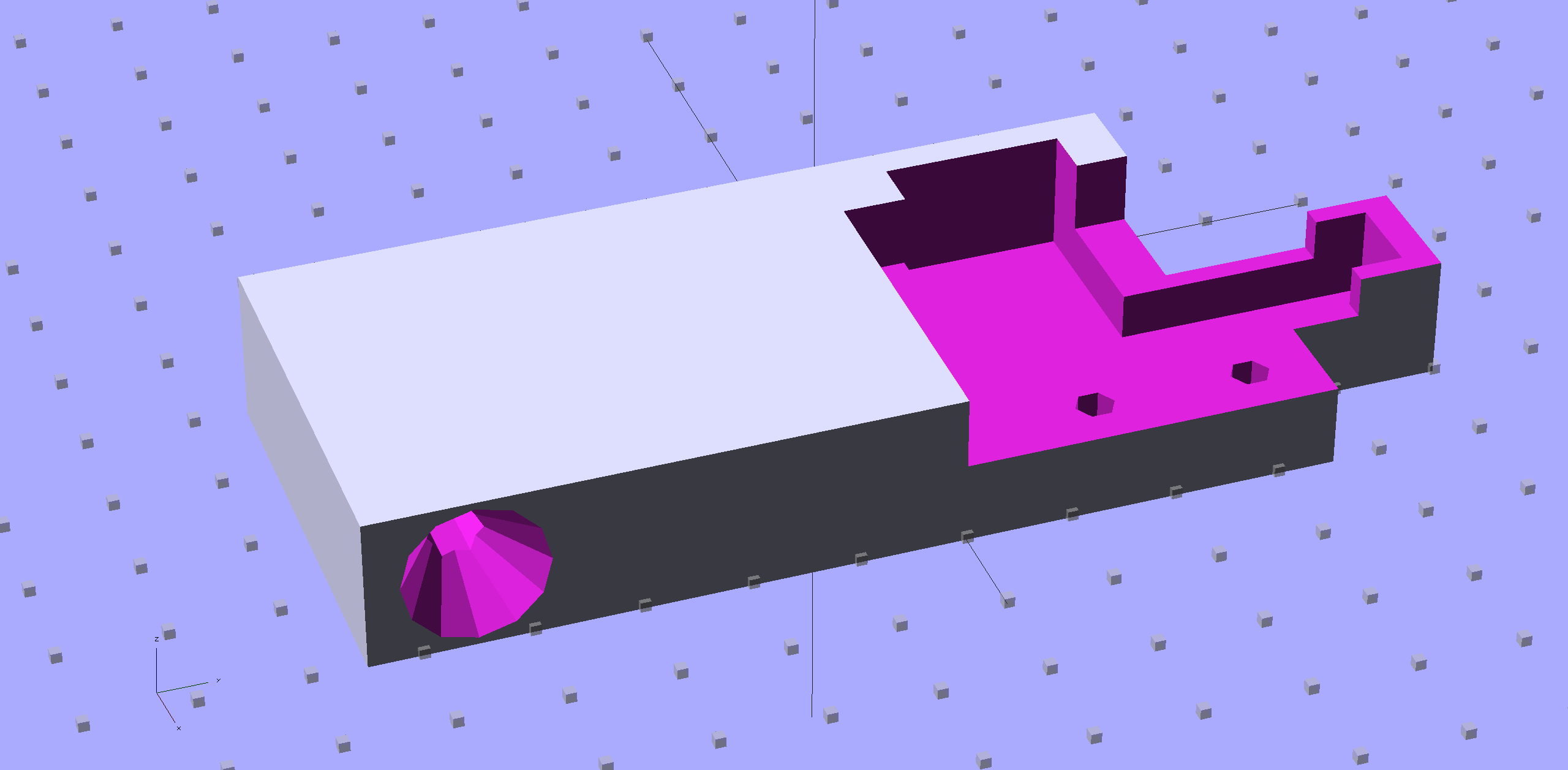
Because the block sits somewhat to the rear of the spool, I added a conical entrance to help ease the filament around the corner into the tube. The hole fits the larger 1/4 inch tube that I’m trying out, with a stop equal to the tube’s 0.17 inch ID just before the conical section, as shown in this cross-section view:
M2 Wire Cover Filament Guide – guide tube section
It fits just about the way you’d expect:
M2 Larger Filament Guide – rear view
The perspective makes the guide tube look more angled than it really is; most of that curve is toward the front, so it’s considerably foreshortened in this view.
The metal bar with the cross pin sticking up in front is a bar clamp that holds an oak strip across the back of the bench to keep the M2 from walking away.
The OpenSCAD source code:
// Improved M2 filament guide and X-min switch wire guide
// Ed Nisley KE4ZNU - Oct 2013

Layout = "Build";				// Build Section

//- Useful Stuff

function IntegerMultiple(Size,Unit) = Unit * ceil(Size / Unit);

Protrusion = 0.1;

HoleWindage = 0.2;

//- Sizes

PlateMinThick = 8.0;				// basic thickness excluding wire guides
PlateLength = 55.0;					// from side of frame beyond top wire guide

TopGuideLength = 7.0;				// protrusion from plate

PlateThick = PlateMinThick + TopGuideLength;

echo(str("Total thickness: ",PlateThick));

GuideTubeOD = 6.3;					// max diameter!
GuideTubeID = 4.3;					// max diameter!
GuideTubeOffset = 45.0;				// centerline from edge of frame

//- Adjust hole diameter to make the size come out right

module PolyCyl(Dia,Height,ForceSides=0) {			// based on nophead's polyholes

  Sides = (ForceSides != 0) ? ForceSides : (ceil(Dia) + 2);

  FixDia = Dia / cos(180/Sides);

  cylinder(r=(FixDia + HoleWindage)/2,h=Height,$fn=Sides);
}

//- Put peg grid on build surface

module ShowPegGrid(Space = 10.0,Size = 1.0) {

  RangeX = floor(100 / Space);
  RangeY = floor(125 / Space);

	for (x=[-RangeX:RangeX])
	  for (y=[-RangeY:RangeY])
		translate([x*Space,y*Space,Size/2])
		  %cube(Size,center=true);

}

//- Define basic block shape
//  Mostly reverse engineered from
//    https://github.com/MakerGear/M2/blob/master/Printed%20Parts/STL/M2%20X%20Endstop%20Wire%20Cover%20with%20Filament%20Guide.stl
//	Hence all the magic numbers...

module BaseBlock() {

SideGuideLength = 4.0;				// protrusion = even with frame interior
ChannelDepth = 4.5;					// wiring channel
FrameOffset = 28;

	translate([18,28,0]) {			// align neatly for later processing

		if (true)
			color("Green",0.2)
				translate([-18,22,15])
					rotate([-90,0,-90])
						import("file:///mnt/bulkdata/Project%20Files/Thing-O-Matic/M2%20Parts/Filament%20Guide/M2+X+Endstop+Wire+Cover+with+Filament+Guide.stl",
								convexity=10);

		difference() {
			linear_extrude(height=PlateThick,convexity=5)		// main block
				polygon(points=[[0,0],[0,22],[12,22],[12,7.5],[22,7.5],
								[22,-(PlateLength + FrameOffset)],[-18,-(PlateLength + FrameOffset)],
								[-18,0]
						]);

			for (i=[-1,0])
				translate([17,((i*15.0)+ 1.05),-Protrusion])
					rotate(180/6) {
						PolyCyl(3.1,(PlateMinThick + 2*Protrusion),6);		// screw holes
						PolyCyl(5.7,(3.0 + Protrusion),6);					//  ... countersink
					}

			translate([0,0,(PlateMinThick - ChannelDepth)])		// wire channel
				linear_extrude(height=15,convexity=5)
					polygon(points=[[2,-5],[2,19],[10,19],[10,-22],[-15,-22],[-15,-5]
							]);

			translate([-10,14,PlateMinThick])				// M2 frame
				rotate(-90)
					cube([42,35,10],center=false);

			translate([-5,5,(PlateMinThick + SideGuideLength)])	// shorten side guide
				cube([20,20,10],center="false");
		}
	}
}

//- Complete object

module GuideCover() {

	difference() {
		BaseBlock();

		translate([50,-GuideTubeOffset,PlateThick/2])
			rotate([0,-90,0])
				rotate(180/6)
					PolyCyl(GuideTubeID,60,6);

		translate([25,-GuideTubeOffset,PlateThick/2])
			rotate([0,-90,0])
				rotate(180/6)
					PolyCyl(GuideTubeOD,60,6);

		translate([41,-GuideTubeOffset,PlateThick/2])
			rotate([0,-90,0])
				rotate(180/6)
					cylinder(r1= 0.5*PlateThick,r2=GuideTubeID/2,h=8,$fn=12);
	}
}

//- Build it

ShowPegGrid();

if (Layout == "Section")
	difference() {
		GuideCover();
		translate([2*100/3,-GuideTubeOffset,-PlateThick])
			rotate(180)
				cube([100,PlateLength,3*PlateThick]);
	}

if (Layout == "Build")
	GuideCover();