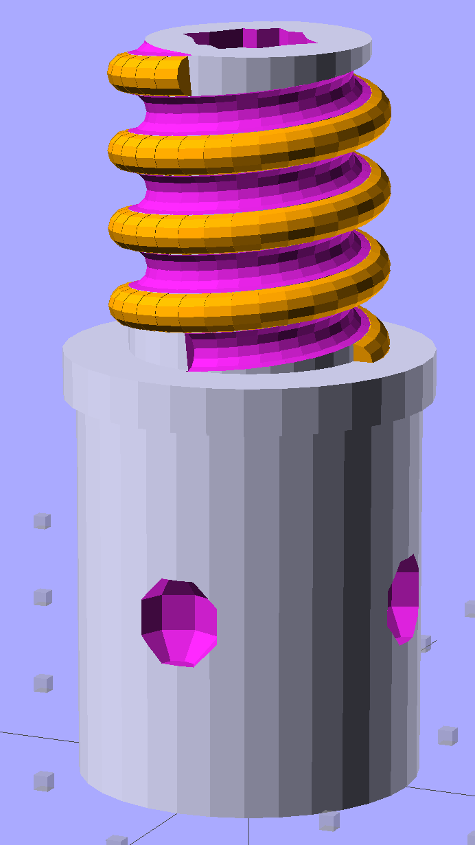
Although the current OpenSCAD could produce a solid model with the screw thread’s dedendum, I’d never actually printed one of them:
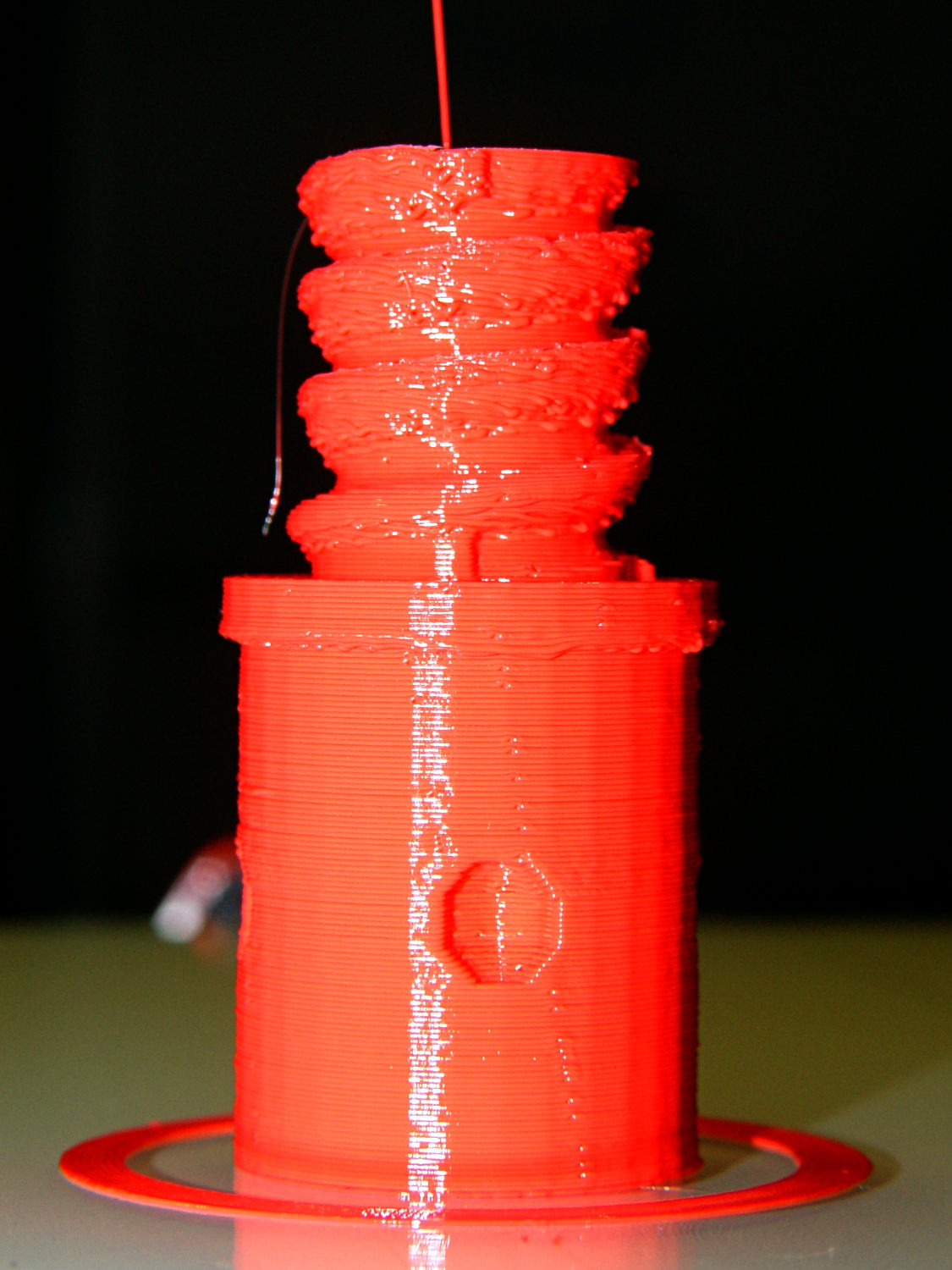
I need some fondlestuff illustrating how to handle overhangs, so I ran one standing vertically, which (pretty much as I expected) didn’t work well at all:
The trick is to split the model down the middle:
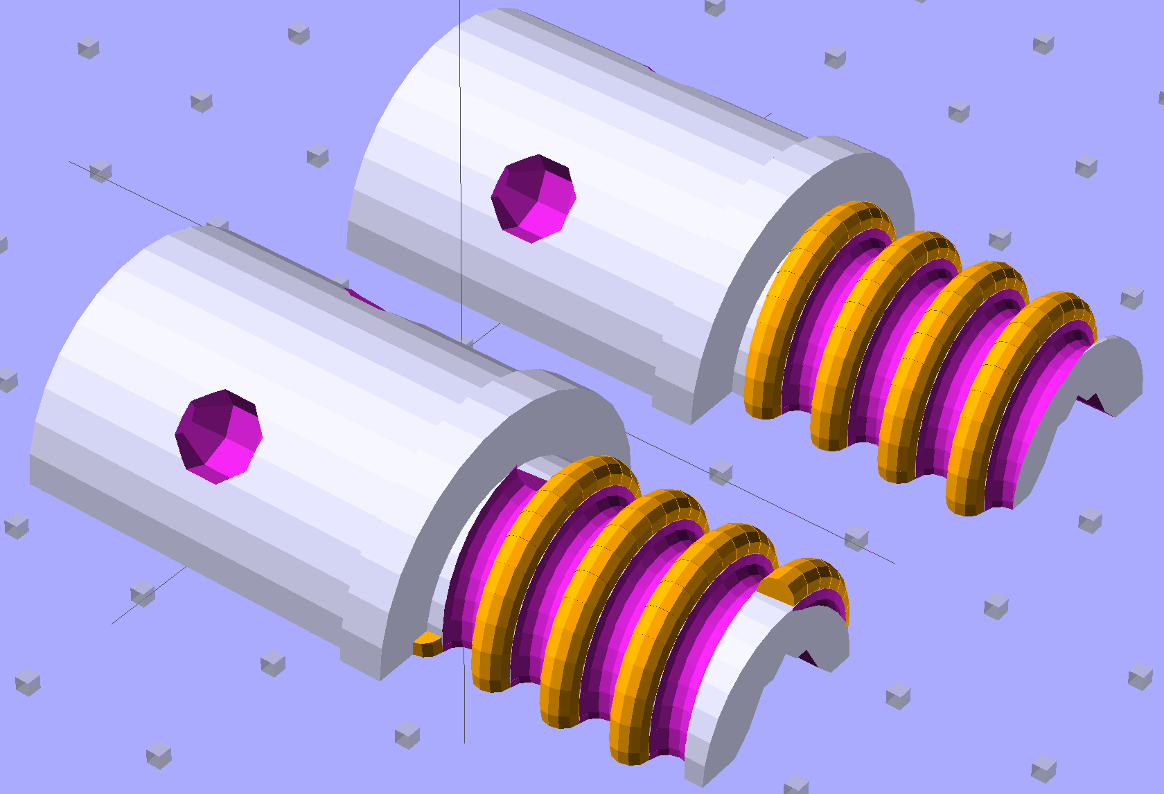
And put holes in each half for alignment pins:

Then you can print it lying down:

The internal overhang would probably call for some support material, particularly in the square recess at the end, but in this case it’s a lesson:
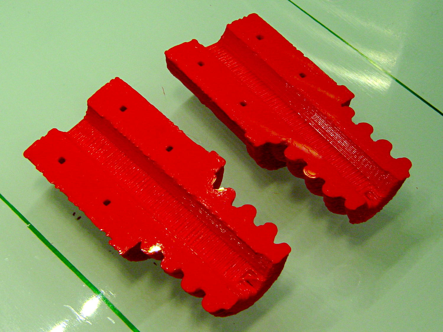
Glue some filament snippets into the holes, snap it together, and it looks just fine over there on the right:

Doesn’t matter how many I print, it still doesn’t make any economic sense as a broom repair…
The OpenSCAD source code now has a Layout variable to control the orientation and, not as shown in the model, the alignment pins have glue gutters in the first layer:
// Broom Handle Screw End Plug
// Ed Nisley KE4ZNU October 2013

Layout = "Horizontal";		// Vertical Horizontal Pin

UseDedendum = true;			// true to create full thread form

//- Extrusion parameters must match reality!

ThreadThick = 0.25;
ThreadWidth = 0.40;

HoleWindage = 0.2;

Protrusion = 0.1;			// make holes end cleanly

//----------------------
// Dimensions

PostOD = 22.3;				// post inside metal handle
PostLength = 25.0;

FlangeOD = 24.0;			// stop flange
FlangeLength = 3.0;

PitchDia = 15.5;			// thread center diameter
ScrewLength = 20.0;

ThreadFormOD = 2.5;			// diameter of thread form
ThreadPitch = 5.0;
NumSegments = 32;			//  .. number of cylinder approximations per turn

BoltOD = 7.0;				// clears 1/4-20 bolt
BoltSquare = 6.5;			// across flats
BoltHeadThick = 3.0;

RecessDia = 6.0;			// recesss to secure post in handle

OALength = PostLength + FlangeLength + ScrewLength;

SplitOC = 1.25*FlangeOD;	// separation in Horizontal layout
PinOD = 1.75;				// alignment pin diameter = filament stub
PinLength = 7.0;			//  ... length

$fn=8*4;					// default cylinder sides

echo("Pitch dia: ",PitchDia);
echo("Root dia: ",PitchDia - ThreadFormOD);
echo("Crest dia: ",PitchDia + ThreadFormOD);

Pi = 3.14159265358979;

//----------------------
// Useful routines

// Wrap cylindrical thread segments around larger plug cylinder

module CylinderThread(Pitch,Length,PitchDia,ThreadOD,PerTurn) {

CylFudge = 1.02;				// force overlap

    RotIncr = 1/PerTurn;
    PitchRad = PitchDia/2;

    Turns = Length/Pitch;
    NumCyls = Turns*PerTurn;

    ZStep = Pitch / PerTurn;

    HelixAngle = atan(Pitch/(Pi*PitchDia));
    CylLength = CylFudge * (Pi*(PitchDia + ThreadOD) / PerTurn) / cos(HelixAngle);

	for (i = [0:NumCyls-1]) {
		assign(Angle = 360*i/PerTurn)
			translate([PitchRad*cos(Angle),PitchRad*sin(Angle),i*ZStep])
				rotate([90+HelixAngle,0,Angle])
					cylinder(r1=ThreadOD/2,
							r2=ThreadOD/(2*CylFudge),
							h=CylLength,
							center=true,$fn=12);
	}
}

// Build complete plug

module ScrewPlug() {
	difference() {
		union() {
			cylinder(r=PostOD/2,h=PostLength);
			cylinder(r=PitchDia/2,h=OALength);
			translate([0,0,PostLength])
				cylinder(r=FlangeOD/2,h=FlangeLength);
			color("Orange")
			translate([0,0,(PostLength + FlangeLength)])
				CylinderThread(ThreadPitch,(ScrewLength - ThreadFormOD/2),PitchDia,ThreadFormOD,NumSegments);
		}

		translate([0,0,-Protrusion])
			PolyCyl(BoltOD,(OALength + 2*Protrusion),6);

		translate([0,0,(OALength - BoltHeadThick)])
			PolyCyl(BoltSquare,(BoltHeadThick + Protrusion),4);

		if (UseDedendum)
			translate([0,0,(PostLength + FlangeLength + ThreadFormOD/2 - ThreadPitch/(2*NumSegments))])
				rotate(-90 - 360/(2*NumSegments))
				CylinderThread(ThreadPitch,ScrewLength,PitchDia,ThreadFormOD,NumSegments);

		for (i = [0:90:270]) {
			rotate(45 + i)					// 45 works better with Horizontal layout
				translate([PostOD/2,0,PostLength/2])
					sphere(r=RecessDia/2,$fn=8);
		}
	}
}

// Locating pin hole with glue recess

module LocatingPin() {

	translate([0,0,-ThreadThick])
		PolyCyl((PinOD + 2*ThreadWidth),2*ThreadThick,4);
	translate([0,0,-(PinLength/2 + ThreadThick)])
		PolyCyl(PinOD,(PinLength + 2*ThreadThick),4);

}

module PolyCyl(Dia,Height,ForceSides=0) {			// based on nophead's polyholes

  Sides = (ForceSides != 0) ? ForceSides : (ceil(Dia) + 2);

  FixDia = Dia / cos(180/Sides);

  cylinder(r=(FixDia + HoleWindage)/2,
           h=Height,
	   $fn=Sides);
}

module ShowPegGrid(Space = 10.0,Size = 1.0) {

  Range = floor(50 / Space);

	for (x=[-Range:Range])
	  for (y=[-Range:Range])
		translate([x*Space,y*Space,Size/2])
		  %cube(Size,center=true);

}

//-------------------
// Build it...

ShowPegGrid();

if (Layout == "Vertical")
	ScrewPlug();

if (Layout == "Pin")
	LocatingPin();

if (Layout == "Horizontal")
	for (i=[-1,1])
		difference() {
			translate([i*SplitOC/2,PostLength/2,0])
				rotate([90,180*(i + 1)/2,0])
					ScrewPlug();

			translate([0,0,-FlangeOD/2])
				cube([2*OALength,2*OALength,FlangeOD],center=true);

			for (j=[-1,1], pin=[-1,1])
				assign(PinX = i*SplitOC/2 + pin*(PostOD + BoltOD)/4,
					   PinY = j*PostLength/4) {
					translate([PinX,PinY,0])
						rotate(45)
							LocatingPin();
					echo("i j pin: ",i,j,pin);
					echo("X Y: ",PinX,PinY);
				}
		}

Comments
2 responses to “Broom Handle Screw With Dedendum: Effect of Printing Orientation”
Is there a strength issue associated with delamination that dictates how you orient a model for printing?
The stresses on the things I print are so low that I’ve never had one fail in service. Beating on some sacrificial victims shows that they separate between the layers (pretty much as you’d expect), so it’s Good Practice to orient the layers so they’re in compression and the lengthwise strands take the tension.
Sometimes, doing both at once is impossible, but I’d say splitting the adapter, printing it in two halves, and then gluing it together would be better than the upright version. But that’s why I ran a bolt down the middle: it keeps the whole cylinder in compression and lets a steel rod handle the bending loads.
Without the bolt, I’d expect the upright adapter to snap between two layers in the exposed flange between the handle and the thread. The split adapter would probably fare better, but I’d still use the bolt…