The Smell of Molten Projects in the Morning

Ed Nisley's Blog: Shop notes, electronics, firmware, machinery, 3D printing, laser cuttery, and curiosities. Contents: 100% human thinking, 0% AI slop.

Tag: CNC

Making parts with mathematics

  • Fu Mask Cutting Templates

    Fu Mask Cutting Templates

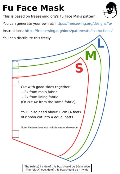
    A local hospital contacted Mary’s quilting group to sew up cloth covers to prolong the life of their medical-grade N95 masks. Their recommended pattern, the Fu Face Mask from the FreeSewing group, comes in three sizes:
    Freesewing - Fu Mask
    Freesewing – Fu Mask

    N.B.: Use their original PDF, because a JPG picture probably won’t come out at the right size.

    Also N.B.: Used by itself, this is not a medical-grade filter mask.

    The patterns do not include the usual 1/4 inch seam allowance around the outside, so I cranked out 3D printed plastic cutting templates.

    If you’re not interested in 3D printing, 2D print the PDF file on cardboard, sketch a seam allowance, and cut it out, as quilters have been doing since slightly after home printers happened.

    The plan of attack:

    • Convert mask outlines into a bitmap image (GIMP)
    • Create Bezier curves by tracing outlines (Inkscape)
    • Save curves as SVG files
    • Convert SVG into solid model (OpenSCAD)
    • Add stiffening ribs &c
    • Save as STL solid model
    • Slice into G-Code file (Slic3r)
    • Fire the M2!

    So, we begin …

    Import the PDF into The GIMP, delete the text & suchlike, convert to monochrome, and save the pattern outlines as a PNG file:

    Fu Facemask - outlines
    Fu Facemask – outlines

    It turns out Inkscape can directly import the PDF, but it valiantly tries to convert all the text and the incidental graphic elements, none of which will be useful in this situation. It’s easier to delete them in The GIMP and make a bank shot off a PNG file.

    Update: Scruss’s comment provides a much simpler workflow!

    Import the PNG into Inkscape and trace one outline with the Bezier curve tool:

    Fu Mask - Inkscape Bezier trace
    Fu Mask – Inkscape Bezier trace

    If you squint really carefully, you’ll see Bezier control handles sticking out of the nodes. I laid three nodes along the top arc and four along the right side, but do what’cha like; the Insert key or Shift+I inserts and Delete removes nodes. It’s easier to center a node in the middle of the PNG line with snapping turned off: Shift+drag while mousing or globally with #.

    You could unleash the bitmap auto-tracer, but it generates a bazillion uselessly tiny Bezier curves.

    When you’re happy, select and copy the path with Ctrl+C, paste it into a shiny new Inkscape document (Ctrl+N) with Ctrl-V, save it with a catchy file name like Fu Mask - Small - nominal.svg, and close that document to return to the document with the PNG outlines and the original path.

    Select the original path again, create a dynamic offset with Ctrl+J, open the XML editor with Ctrl+Shift+X (which automagically selects the proper SVG element), and change the inkscape:radius value from 0 to 6.35 (mm, which everyone should use) to get a 1/4 inch seam allowance:

    Fu Mask - Inkscape XML Editor - Offset radius
    Fu Mask – Inkscape XML Editor – Offset radius

    The path will puff out with curved corners:

    Fu Mask - Inkscape offset
    Fu Mask – Inkscape offset

    Copy into a new document, save as Fu Mask - Small - seam allowance.svg, and close.

    Repeat that process for each of the three mask sizes to create three pairs of SVG files: the nominal mask outline and the corresponding seam allowance outline for each size.

    The OpenSCAD program imports the SVG files, removes the nominal outline from within the seam allowance to leave the outline, adds stiffening ribs, and stamps an ID letter on both sides of the central button:

    Fu Mask Cutting Template - Small - solid model
    Fu Mask Cutting Template – Small – solid model

    Choose one of the three sizes with the OpenSCAD customizer, save the resulting model as an STL file, repeat for the three sizes, and you’re done.

    This process can convert any outline paths in SVG files into cutting templates, so, should the Fu Mask not suit your fancy, Use The Source.

    For convenience, the STL files are on Thingiverse.

    From the comments, a Washington hospital uses a similar pattern: their PDF with assembly instructions.

    The OpenSCAD source code as a GitHub Gist:

    // Fu Mask cutting templates
    // Ed Nisley – KE4ZNU – 2020-03
    // Mask patterns from:
    // https://freesewing.org/blog/facemask-frenzy/
    // More info on my blog:
    // https://softsolder.com/2020/03/29/fu-mask-cutting-templates/
    /* [Mask Size] */
    Name = "Small"; // [Small, Medium, Large, Test]
    /* [Hidden] */
    Templates = [ // center ID letter and file name
    ["S","Small"],
    ["M","Medium"],
    ["L","Large"],
    ["T","Test"], // for whatever you like
    ];
    T_ID = 0; // Template indexes
    T_NAME = 1;
    BarThick = 4.0; // template thickness
    HubOD = 20.0; // center button diameter
    // These should match slicer values
    ThreadThick = 0.25;
    ThreadWidth = 0.40;
    Protrusion = 0.1; // make clean holes
    //— Build it
    t = Templates[search([Name],Templates,1,1)[0]]; // find template index
    Dir = "./";
    FnOuter = str(Dir,"Fu Facemask – ",t[T_NAME]," – seam allowance.svg");
    FnInner = str(Dir,"Fu Facemask – ",t[T_NAME]," – nominal.svg");
    difference() {
    linear_extrude(BarThick,convexity=5) {
    intersection() {
    import(FnOuter,center=true);
    union() {
    square([200.0,5.0],center=true); // horizontal bar
    square([5.0,200.0],center=true); // vertical bar
    }
    }
    circle(d=HubOD); // central button
    difference() { // cutting template!
    import(FnOuter,center=true);
    import(FnInner,center=true);
    }
    }
    translate([0,0,BarThick – ThreadThick]) // top ID recess
    cylinder(d=HubOD – 6*ThreadWidth,h=ThreadThick + Protrusion);
    translate([0,0,-Protrusion]) // bottom ID recess
    cylinder(d=HubOD – 6*ThreadWidth,h=ThreadThick + Protrusion);
    }
    translate([0,0,2*BarThick/3]) // top ID
    linear_extrude(height=BarThick/3,convexity=2)
    text(text=t[T_ID],size=10,
    font="Arial:style:Bold",halign="center",valign="center");
    mirror([1,0,0]) // bottom ID
    linear_extrude(height=BarThick/3,convexity=2)
    text(text=t[T_ID],size=10,
    font="Arial:style:Bold",halign="center",valign="center");

    Verily, there’s nothing like a good new problem to take your mind off all your old problems …

  • Drag Knife Calibration: Downforce and Speed

    Drag Knife Calibration: Downforce and Speed

    The drag knife faceplant suggested I must pay a bit more attention to fundamentals, so, with a 60° drag knife blade sticking out a reasonable amount, the next step is to see what effect the cutting “depth” (a.k.a. downforce) and speed have on the outcome.

    A smidge of GCMC code later:

    Drag Knife Cal - depth - overview - Camotics sim
    Drag Knife Cal – depth – overview – Camotics sim

    It’s not obvious, but each pattern steps downward by 0.5 mm from left to right. With the spring force equal to 375 g + 57 g/mm, the downforce ranges from 400 to 520 g over the five patterns.

    Laminated scrap, meet drag knife:

    Drag Knife Cal - Depth - as cut
    Drag Knife Cal – Depth – as cut

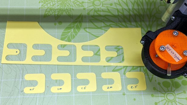
    Pulling up on the surrounding scrap left the patterns on the sticky mat:

    Drag Knife Cal - Depth - extracted
    Drag Knife Cal – Depth – extracted

    Which suggested any cutting force would work just fine.

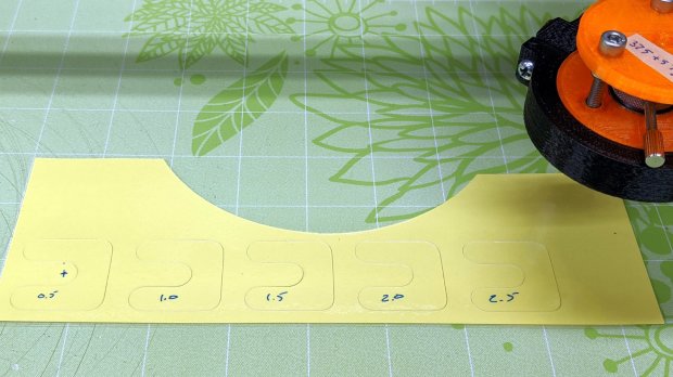
    Flushed with success, I cut some speed variations at the minimum depth of Z=-0.5 mm = 400 g:

    Drag Knife Cal - Speed - 0.5 mm - as cut
    Drag Knife Cal – Speed – 0.5 mm – as cut

    The blade cut through the top laminating film, the paper, and some sections of the bottom film, but mostly just scored the latter.

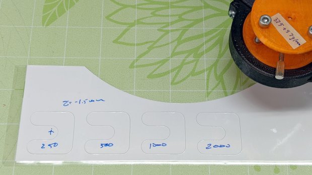
    Repeating at Z=-1.5 mm = 460 g didn’t look much different:

    Drag Knife Cal - Speed - 1.5 mm - as cut
    Drag Knife Cal – Speed – 1.5 mm – as cut

    However, the knife completely cut all the patterns:

    Drag Knife Cal - Speed - 1.5 mm - extracted
    Drag Knife Cal – Speed – 1.5 mm – extracted

    As far as I can tell, the cutting speed doesn’t make much difference, although the test pattern is (deliberately) smooth & flowy like the Tek CC deck outlines. I’d been using 1000 mm/min and 2000 mm/min seems scary-fast, so 1500 mm/min may be a good compromise.

    The GCMC source code as a GitHub Gist:

    // Calibrate Drag Knife – speed & feed
    // Ed Nisley – KE4ZNU
    // 2020-03 values for MPCNC
    //—–
    // Dimensions
    CutIncr = -0.5mm;
    BottomCutZ = -2.5mm;
    SpeedRatio = 2.0;
    MaxSpeed = 2000mm;
    MinSpeed = MaxSpeed / 8;
    StripWidth = 10mm;
    CornerRadius = StripWidth/2;
    PatternSize = StripWidth * [3,3];
    PatternSpace = 1.25;
    SafeZ = 10.0mm; // above all obstructions
    TravelZ = 2.0mm; // within engraving / milling area
    FALSE = 0;
    TRUE = !FALSE;
    if (!isdefined("TestSelect")) {
    TestSelect = "Depth";
    }
    comment("Test Selection: ",TestSelect);
    //—–
    // One complete pattern
    // Centered at ctr, ctr.z=cut depth
    function Pattern(ctr) {
    local d1 = CornerRadius; // useful relative distances
    local d2 = 2*d1;
    local d3 = 3*d1;
    local d4 = 4*d1;
    goto([-,-,TravelZ]); // set up for entry move
    goto(head(ctr,2) + [-d2,d3]);
    move([ctr.x + d2,-,ctr.z]); // enter to cut depth
    arc_cw_r([d1,-d1],d1);
    move_r([0,-d4]);
    arc_cw_r([-d1,-d1],d1);
    move_r([-d4,0]);
    arc_cw_r([0,d2],d1);
    move_r([d2,0]);
    arc_ccw_r([0,d2],d1);
    move_r([-d2,0]);
    arc_cw_r([0,d2],d1);
    move_r([d4,0]); // re-cut entire entry path
    goto([-,-,TravelZ]); // exit to surface
    // goto(head(ctr,2));
    }
    //—–
    // Start cutting!
    goto([-,-,SafeZ]);
    goto([0,0,-]);
    goto([-,-,TravelZ]);
    if (TestSelect == "Depth") {
    comment("Depth variations");
    s = MaxSpeed / 2;
    feedrate(s);
    c = [0,0,-]; // initial center at origin
    for (c.z = CutIncr; c.z >= BottomCutZ; c.z += CutIncr) {
    comment("At: ",c," speed:",s);
    Pattern(c);
    c.x += PatternSpace * PatternSize.x;
    }
    }
    if (TestSelect == "Speed") {
    comment("Speed variations");
    c = [0,0,-2mm]; // initial center at origin
    for (s = MinSpeed; s <= MaxSpeed; s *= SpeedRatio) {
    comment("At: ",c," speed: ",s);
    feedrate(s);
    Pattern(c);
    c.x += PatternSpace * PatternSize.x;
    }
    }
    goto([-,-,SafeZ]);
    goto([0,0,-]);

  • Drag Knife Blade Extension

    Drag Knife Blade Extension

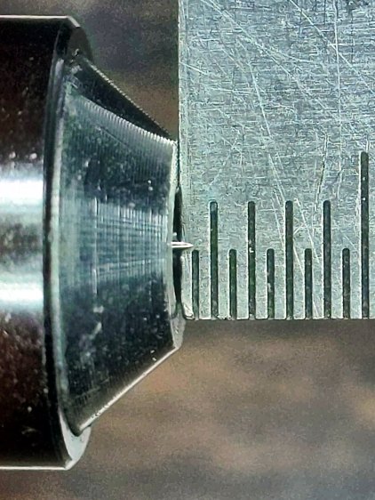
    The battered corner of my bench scale shows it’s been knocking around for quite a while, but the drag knife blade tip seems pretty close to the first 0.5 mm division:

    Drag Knife Blade - 0.5 mm
    Drag Knife Blade – 0.5 mm

    The blade extends from the LM12UU holder for the MPCNC.

    Scribbling the blade across a scrap of laminated yellow card stock (about 0.4 mm thick) showed it didn’t cut all the way through the bottom plastic layer, even with the spring mashed flat.

    So I screwed it out to 0.7 mm:

    Drag Knife Blade - 0.7 mm
    Drag Knife Blade – 0.7 mm

    The scale isn’t quite parallel to the blade axis and maybe it’s sticking out 0.8 mm; setting a drag knife’s blade extension obviously isn’t an exact science.

    In any event, another scribble slashed all the way through the laminated deck without gashing the sacrificial cardboard atop my desk, which seems good enough.

  • Round Soaker Hose Splint

    Round Soaker Hose Splint

    One of two new round rubber soaker hoses arrived with a slight crimp, enough to suggest it would crumble at an inopportune moment. Rather than return the hose for something that’s not an obvious failure, I clamped the crimp:

    Round Soaker Hose Splice - top
    Round Soaker Hose Splice – top

    Unlike the clamps for the punctured flat soaker hoses, this one doesn’t need to withstand much pressure and hold back a major leak, so I made the pieces a bit thicker and dispensed with the aluminum backing plates:

    Round Soaker Hose Splice - bottom
    Round Soaker Hose Splice – bottom

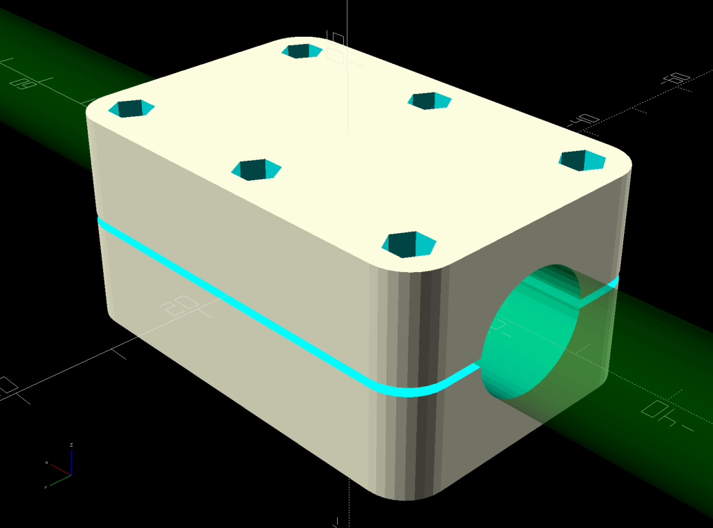
    The solid model is basically the same as for the flat hoses, with a slightly oval cylinder replacing the three channels:

    Round Soaker Hose Splice - OpenSCAD model
    Round Soaker Hose Splice – OpenSCAD model

    The OpenSCAD source code as a GitHub Gist:

    // Rubber Soaker Hose Splice
    // Ed Nisley KE4ZNU 2020-03
    Layout = "Build"; // [Hose,Block,Show,Build]
    TestFit = false; // true to build test fit slice from center
    //- Extrusion parameters must match reality!
    /* [Hidden] */
    ThreadThick = 0.25;
    ThreadWidth = 0.40;
    HoleWindage = 0.2;
    Protrusion = 0.1; // make holes end cleanly
    inch = 25.4;
    function IntegerMultiple(Size,Unit) = Unit * ceil(Size / Unit);
    ID = 0;
    OD = 1;
    LENGTH = 2;
    //———-
    // Dimensions
    // Hose lies along X axis
    Hose = [200,14.5,13.6]; // X = longer than anything else
    // 8-32 stainless screws
    Screw = [4.1,8.0,3.0]; // OD = head LENGTH = head thickness
    Washer = [4.4,9.5,1.0];
    Nut = [4.1,9.7,6.0];
    Block = [50.0,Hose.y + 2*Washer[OD],4.0 + 1.5*Hose.z]; // overall splice block size
    echo(str("Block: ",Block));
    Kerf = 1.0; // cut through middle to apply compression
    CornerRadius = Washer[OD]/2;
    NumScrews = 3; // screws along each side of cable
    ScrewOC = [(Block.x – 2*CornerRadius) / (NumScrews – 1),
    Block.y – 2*CornerRadius,
    2*Block.z // ensure complete holes
    ];
    echo(str("Screw OC: x=",ScrewOC.x," y=",ScrewOC.y));
    //———————-
    // Useful routines
    module PolyCyl(Dia,Height,ForceSides=0) { // based on nophead's polyholes
    Sides = (ForceSides != 0) ? ForceSides : (ceil(Dia) + 2);
    FixDia = Dia / cos(180/Sides);
    cylinder(d=(FixDia + HoleWindage),h=Height,$fn=Sides);
    }
    // Hose shape
    // This includes magic numbers measured from reality
    module HoseProfile() {
    NumSides = 12*4;
    rotate([0,-90,0])
    translate([0,0,-Hose.x/2])
    resize([Hose.z,Hose.y,0])
    cylinder(d=Hose.z,h=Hose.x,$fn=NumSides);
    }
    // Outside shape of splice Block
    // Z centered on hose rim circles, not overall thickness through center ridge
    module SpliceBlock() {
    difference() {
    hull()
    for (i=[-1,1], j=[-1,1]) // rounded block
    translate([i*(Block.x/2 – CornerRadius),j*(Block.y/2 – CornerRadius),-Block.z/2])
    cylinder(r=CornerRadius,h=Block.z,$fn=4*8);
    for (i = [0:NumScrews – 1], j=[-1,1]) // screw holes
    translate([-(Block.x/2 – CornerRadius) + i*ScrewOC.x,
    j*ScrewOC.y/2,
    -(Block.z/2 + Protrusion)])
    PolyCyl(Screw[ID],Block.z + 2*Protrusion,6);
    cube([2*Block.x,2*Block.y,Kerf],center=true); // slice through center
    }
    }
    // Splice block less hose
    module ShapedBlock() {
    difference() {
    SpliceBlock();
    HoseProfile();
    }
    }
    //———-
    // Build them
    if (Layout == "Hose")
    HoseProfile();
    if (Layout == "Block")
    SpliceBlock();
    if (Layout == "Show") {
    difference() {
    SpliceBlock();
    HoseProfile();
    }
    color("Green",0.25)
    HoseProfile();
    }
    if (Layout == "Build") {
    SliceOffset = TestFit && !NumScrews%2 ? ScrewOC.x/2 : 0;
    intersection() {
    translate([SliceOffset,0,Block.z/4])
    if (TestFit)
    cube([ScrewOC.x/2,4*Block.y,Block.z/2],center=true);
    else
    cube([4*Block.x,4*Block.y,Block.z/2],center=true);
    union() {
    translate([0,0.6*Block.y,Block.z/2])
    ShapedBlock();
    translate([0,-0.6*Block.y,Block.z/2])
    rotate([0,180,0])
    ShapedBlock();
    }
    }
    }

  • CNC Kitchen Sink Strainer

    CNC Kitchen Sink Strainer

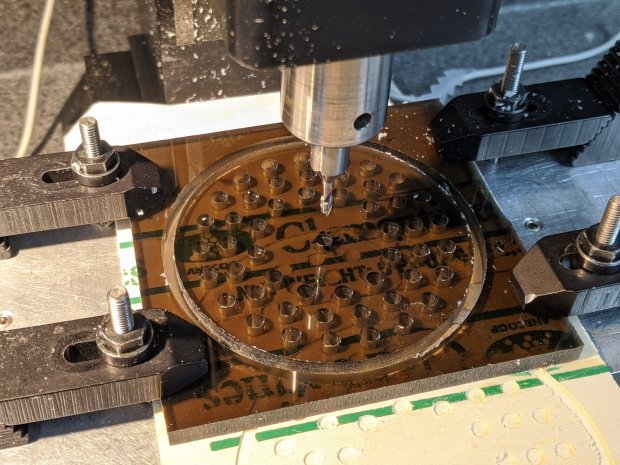
    Our Young Engineer recently rented a house, now knows why our sinks have CNC-machined strainers, and asked for something better than the disgusting stainless mesh strainer in the kitchen sink.

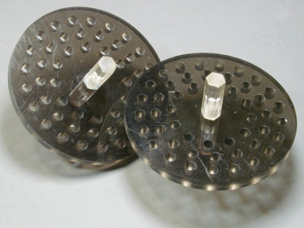
    Being a doting father, I turned out a pair to get a pretty one:

    CNC Sink Strainer - overview
    CNC Sink Strainer – overview

    They’re made from the same scrap smoked acrylic as the ones in our sinks:

    CNC Sink Strainer
    CNC Sink Strainer

    They’re definitely upscale from the (not watertight!) 3D printed version I built for a Digital Machinist column to explain OpenSCAD modeling:

    Strainer plate fill
    Strainer plate fill

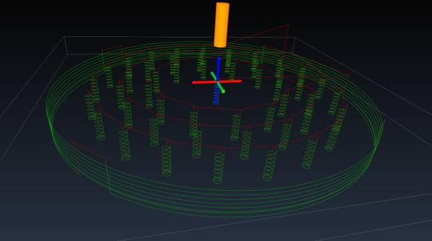
    This time around, though, I rewrote the subtractive design in GCMC, with helical milling for all the holes to eliminate the need to change tools:

    Sink Strainer - tool path simulation - CAMotics
    Sink Strainer – tool path simulation – CAMotics

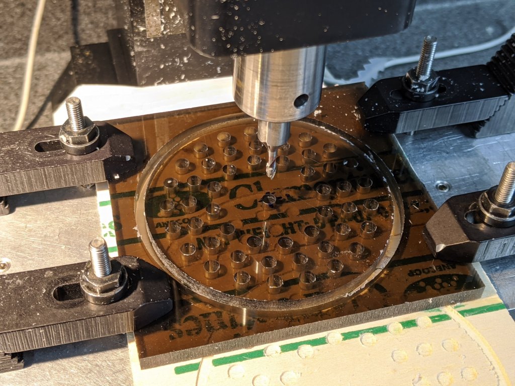
    They’re done on the Sherline, because it has real clamps:

    CNC Sink Strainer - on Sherline
    CNC Sink Strainer – on Sherline

    Four tabs eliminated the need to reclamp the stock before cutting the perimeter, but I should have ramped, not plunged, through the final cut between the tabs:

    CNC Sink Strainer - tab surface fracture
    CNC Sink Strainer – tab surface fracture

    The handles come from the same chunk of hex acrylic as before, eyeballed to length, tapped 8-32, and secured with acrylic adhesive.

    The GCMC source code as a GitHub Gist:

    // Drill & mill sink drain strainer
    // Ed Nisley KE4ZNU — Digital Machinist 15.2 Spring 2020
    // polycarbonate or acrylic sheet
    // External clamps at corners
    // Origin at center of sheet
    //—–
    // Dimensions
    DiskOD = 80.0mm; // usual kitchen drain = 3-1/4 inch
    DiskRad = DiskOD/2;
    PlateThick = 6.0mm; // stock thickness
    MillOD = 3.170mm; // measured end mill OD
    HoleDia = 4.75mm; // 3/16 inch drain holes
    ScrewOD = 0.18in; // knob screw clearance
    NumRings = 3; // rings of drain holes
    RingSpace = 1.5 * HoleDia; // .. between rings
    MaxZCut = 0.25 * MillOD; // max cut depth
    MillSpeed = 1000mm; // horizontal feedrate
    NumTabs = 4;
    TabTilt = 45deg;
    TabLength = 5.0mm;
    TabThick = 0.5mm;
    SafeZ = 10.0mm; // above all obstructions
    TravelZ = 1.0mm; // within engraving / milling area
    MillZ = -(PlateThick + 0.5mm); // through disk into spoil board
    TwoPi = 2*pi();
    //—–
    // Mill one hole
    function MillHole(ctr,radius,turns) {
    goto([-,-,TravelZ]);
    goto(head(ctr,2) + [radius,-,-]);
    goto([-,-,0]); // kiss surface
    circle_cw(ctr,turns); // helix downward
    circle_cw(head(ctr,2)); // remove last ramp
    goto(ctr); // get elbow room
    goto([-,-,TravelZ]);
    }
    //—–
    // Start cutting!
    goto([-,-,SafeZ]);
    goto([0,0,-]);
    goto([-,-,TravelZ]);
    feedrate(MillSpeed);
    // Mill center screw hole
    comment("– Center hole");
    ctr = [0,0,MillZ];
    MillHole(ctr,(ScrewOD – MillOD) / 2,ceil(abs(ctr.z) / MaxZCut));
    // Mill hole rings
    comment("– Drain hole rings");
    repeat (NumRings; ri) {
    comment("Ring: ",ri);
    rr = DiskRad – ri*RingSpace; // ring radius
    comment(" radius: ",rr);
    nh = to_int(floor(TwoPi*rr / (2*HoleDia))); // number of holes
    comment(" holes: ",nh);
    repeat(nh; h) {
    a = (h – 1) * TwoPi / nh; // angle of hole
    ctr = [rr*cos(a),rr*sin(a),MillZ]; // center point at ending Z
    MillHole(ctr,(HoleDia – MillOD)/2,ceil(abs(ctr.z) / MaxZCut));
    }
    }
    // Mill perimeter
    comment("– Perimeter");
    r = DiskRad + MillOD/2;
    goto([r,0,-]);
    goto([-,-,0]);
    ctr = [0,0,-(PlateThick – TabThick)];
    circle_ccw(ctr,ceil(abs(ctr.z) / MaxZCut)); // ramp downward
    circle_ccw(ctr,1); // remove last ramp
    goto([-,-,TravelZ]);
    comment("– Tabs");
    ta = 360deg / NumTabs; // between tabs
    tsa = to_rad(TwoPi*((TabLength + MillOD) / (TwoPi * r))); // subtended tab angle
    repeat (NumTabs; i) {
    comment(" # ",i);
    a = TabTilt + (i – 1)*ta; // tab center angle
    p0 = [r*cos(a + tsa/2),r*sin(a + tsa/2),MillZ]; // entry on ccw side
    p1 = [r*cos(a + ta – tsa/2),r*sin(a + ta – tsa/2),MillZ]; // exit at next tab
    if (0) {
    comment(" angle: ",a);
    comment(" entry: ",p0);
    comment(" exit: ",p1);
    }
    goto(head(p0,2)); // to entry point
    move(p0); // plunge through
    arc_ccw(p1,r);
    goto([-,-,TravelZ]);
    }
    goto([-,-,SafeZ]);
    goto([0,0,-]);

    All in all, a pleasant diversion from contemporary events …

  • GRBL Error 33: Arc Coordinates vs. Decimal Places

    GRBL Error 33: Arc Coordinates vs. Decimal Places

    The LinuxCNC G2/G3 arc command doc has this to say about numerical precision:

    When programming arcs an error due to rounding can result from using a precision of less than 4 decimal places (0.0000) for inch and less than 3 decimal places (0.000) for millimeters.

    So I normally set GCMC to produce three decimal digits, because its default of eight digits seems excessive for my usual millimeter measurements, and assume whatever G-Code sender I use won’t chop digits off the end in passing. Mistakenly setting bCNC to round at two decimal places showed what happens with fewer digits, as bCNC’s default is four decimal digits.

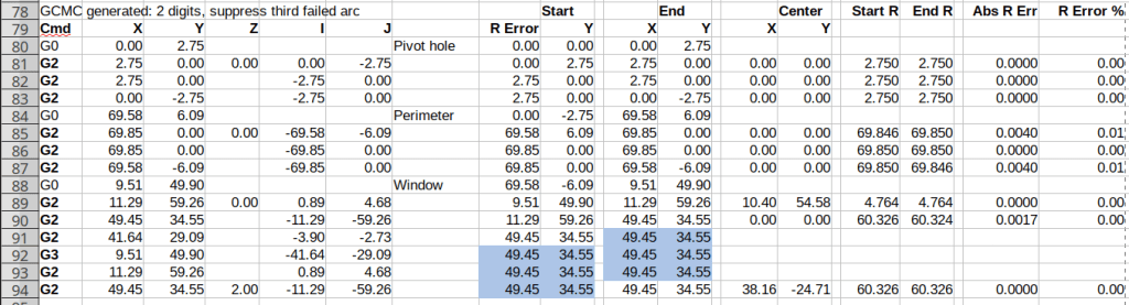
    A closer look at the coordinates in the lower right part of the spreadsheets (from yesterday) shows the limited accuracy with two decimal digits:

    Spreadsheet - GCMC 2 digit - full path - detail
    Spreadsheet – GCMC 2 digit – full path – detail

    The red blocks mark the first failing arc, where the relative error falls out of tolerance. If GRBL were less fussy (which it should not be), then the next arcs would proceed as shown.

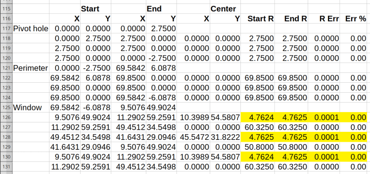
    Rounding to three decimal digits pushes the errors into to the third place, with the yellow highlight marking the worst errors:

    Spreadsheet - GCMC 3 digit - detail
    Spreadsheet – GCMC 3 digit – detail

    As you should expect, the smallest arcs have the largest relative errors, although they’re now well within GRBL’s (and LinuxCNC’s, for that matter) limits.

    Rounding to four decimal digits makes the errors vanishingly small:

    Spreadsheet - GCMC 4 digit - detail
    Spreadsheet – GCMC 4 digit – detail

    So, by and large, don’t scrimp on the decimal digits … but we knew that already.

    I’d been setting GRBL to produce three decimal places, but now I’m using four. Adding a few characters to each G-Code command reduces the number of commands fitting into GRBL’s buffer space, but bCNC normally keeps it around 90% full, so the path planner should remain perfectly happy.

  • GRBL Error 33: G-Code Arc Tolerances

    GRBL Error 33: G-Code Arc Tolerances

    After figuring out how two-place decimal fractions caused this blooper, I had to poke into the debris field surrounding the crash:

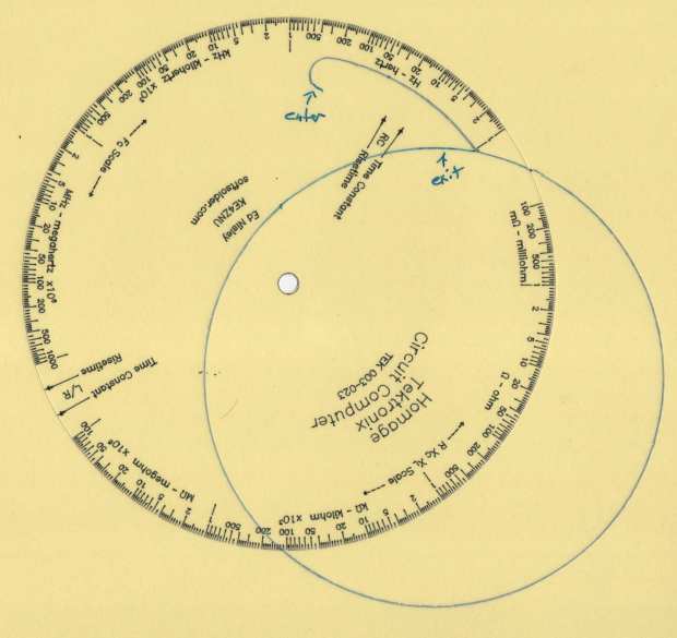
    Tek CC - top deck - failed arcs
    Tek CC – top deck – failed arcs

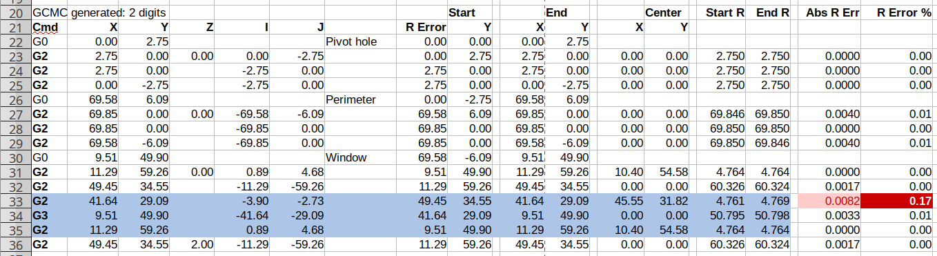
    The bCNC Terminal trace stops at the first failure, so I set GCMC to produce two-place fractions (“Number of decimals less than 3 severely limits accuracy”), then rammed the NGC file’s G-Code into a spreadsheet:

    Spreadsheet - GCMC 2 digit - full path
    Spreadsheet – GCMC 2 digit – full path

    The last two columns (perhaps you must open the image in a new tab to see the whole thing) compute the GRBL error values: the absolute difference between the two radii and that difference as a fraction of the radius. The R Error header under Start should be X, of course; I’ll regenerate the images for the DM column.

    The reduced accuracy of the two-digit fractions triggers the error marked by the red cells, where the radii differ by 0.0082 mm (>0.005) and the relative error is 0.17% (>0.1%).

    Suppressing the first failed arc by passing the same starting point to the next arc simulates the second failure:

    Spreadsheet - GCMC 2 digit - suppress first failed arc
    Spreadsheet – GCMC 2 digit – suppress first failed arc

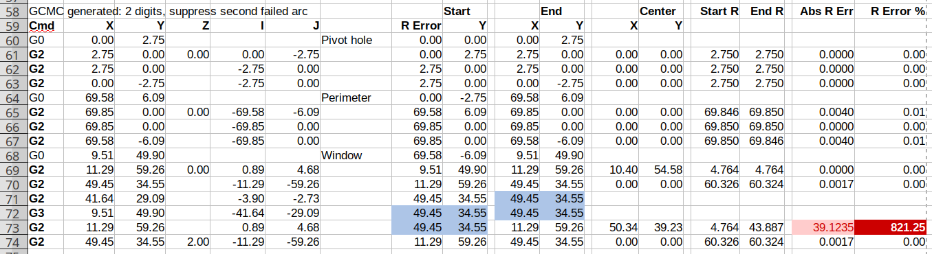
    Similarly, the third arc from the same point fails:

    Spreadsheet - GCMC 2 digit - suppress second failed arc
    Spreadsheet – GCMC 2 digit – suppress second failed arc

    The fourth arc becomes a full circle and produces the circular gash across the deck:

    Spreadsheet - GCMC 2 digit - suppress third failed arc
    Spreadsheet – GCMC 2 digit – suppress third failed arc

    Two digits definitely aren’t enough!