The Smell of Molten Projects in the Morning

Ed Nisley's Blog: Shop notes, electronics, firmware, machinery, 3D printing, laser cuttery, and curiosities. Contents: 100% human thinking, 0% AI slop.

Tag: CNC

Making parts with mathematics

  • Shuttles Board Game: Replacement Pegs

    Shuttles Board Game: Replacement Pegs

    For reasons not relevant here, I made replacement pegs for the Shuttles board game:
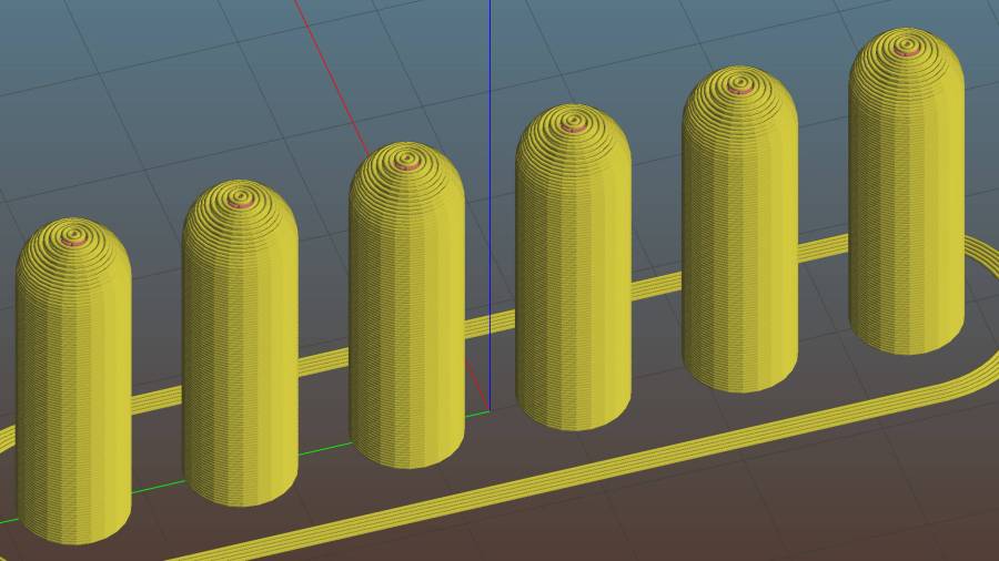
    Shuttles Game - solid model - Slic3r
    Shuttles Game – solid model – Slic3r

    Not the most challenging solid model I’ve ever conjured from the vasty digital deep, but 3D printing is really good for stuff like this.

    The OEM pegs have a hollow center, most likely to simplify stripping them from the injection mold, which I dutifully duplicated:

    Shuttles Game pegs - hollow - solid model
    Shuttles Game pegs – hollow – solid model

    It turns out the additional perimeter length inside the pegs requires 50% more printing time, far offsetting the reduced 10% infill. Given that each solid set takes just under an hour, I decided to lose half an hour of verisimilitude.

    I plunked a nice round cap atop the OEM peg’s flat end, but stopped short of printing & installing a round plug for the butt end.

    While the 3D printer’s hot, ya may as well make a bunch:
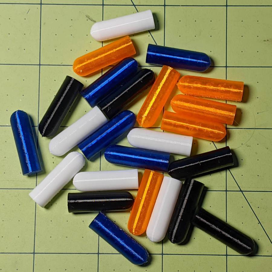
    Shuttles game pegs
    Shuttles game pegs

    Game on …

    The OpenSCAD source code as a GitHub Gist:

    Update: They’re a bit too large, so the Gist now produces tapered pegs.

    // Shuttles game pegs
    // Ed Nisley KE4ZNU – July 2020
    /* [Layout Options] */
    Layout = "Peg"; // [Build, Peg]
    Hollow = false;
    //——-
    //- Extrusion parameters must match reality!
    /* [Hidden] */
    ThreadThick = 0.25;
    ThreadWidth = 0.40;
    HoleWindage = 0.2;
    Protrusion = 0.1; // make holes end cleanly
    ID = 0;
    OD = 1;
    LENGTH = 2;
    //——-
    // Dimensions
    /* [Dimensions] */
    Peg = [4.0,7.5,26.0]; // overall length, including the rounded Cap
    Taper = 1.0;
    CapRadius = Peg[OD]/2;
    PegBaseLength = Peg[LENGTH] – CapRadius;
    NumPegs = [1,6]; // lay out in array
    ArrayCenter = [NumPegs[0] – 1,NumPegs[1] – 1] / 2;
    NumSides = 6*4;
    //——-
    module PolyCyl(Dia,Height,ForceSides=0) { // based on nophead's polyholes
    Sides = (ForceSides != 0) ? ForceSides : (ceil(Dia) + 2);
    FixDia = Dia / cos(180/Sides);
    cylinder(r=FixDia/2 + HoleWindage,h=Height,$fn=Sides);
    }
    //——-
    // One peg
    module Peg() {
    union() {
    translate([0,0,PegBaseLength])
    difference() {
    sphere(d=Peg[OD],$fn=NumSides);
    translate([0,0,-Peg[OD]/2])
    cube([2*Peg[OD],2*Peg[OD],Peg[OD]],center=true);
    }
    difference() {
    cylinder(d1=Peg[OD] – Taper,d2=Peg[OD],h=PegBaseLength,$fn=NumSides);
    if (Hollow)
    translate([0,0,-Protrusion])
    PolyCyl(Peg[ID],PegBaseLength+Protrusion,NumSides);
    }
    }
    }
    //——-
    // Build it!
    if (Layout == "Peg")
    Peg();
    if (Layout == "Build")
    for (i=[0:NumPegs[0] – 1], j=[0:NumPegs[1] – 1])
    translate([(i – ArrayCenter.x)*1.5*Peg[OD],(j – ArrayCenter.y)*1.5*Peg[OD],0])
    Peg();

  • Garden Soaker Hose Repairs In Use

    Garden Soaker Hose Repairs In Use

    Just for completeness, here’s what the various soaker hose clamps look like in the garden, as solid models only let you visualize the ideal situation:

    Soaker Hose Connector Clamp - Show view
    Soaker Hose Connector Clamp – Show view

    This one prevents a puddle in the path to the right:

    Soaker hose repairs in situ - clamp
    Soaker hose repairs in situ – clamp

    Bending the hoses around the end of a bed puts them on edge, with this clamp suppressing a shin-soaking spray to the left:

    Soaker hose repairs in situ - end-on clamp
    Soaker hose repairs in situ – end-on clamp

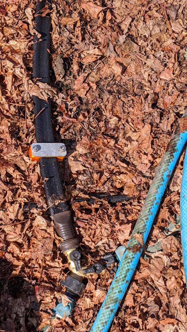
    The clamp at the connector closes a leak around the crimped brass fitting, with the other two preventing gouges from direct sprays into the path along the bottom of the picture:

    Soaker hose repairs in situ - clamps and connector fix
    Soaker hose repairs in situ – clamps and connector fix

    All in all, a definite UI improvement!

    As far as I can tell, we have the only soaker hose repairs & spritz stoppers in existence. Hooray for 3D printing!

  • Maximum 3D Printing Speed

    Maximum 3D Printing Speed

    With everybody 3D printing masks these days, the question of “how fast can you print” came up on the Makergear forum.

    Here’s my opinion:

    The fundamental limit comes from the heater’s ability to bring cold plastic up to extrusion temperature inside the 20 mm hot zone.

    Using airscape’s example, the extruded thread is 0.5 mm thick × 0.8 mm wide = 0.4 mm², so laying down that thread at 50 mm/s means the extruder is heating plastic at 20 mm³/s and is “pushing it with PLA”.

    In round numbers, normal printing speeds with a normal nozzle and normal plastics runs around 10 mm³/s, so a practical upper limit is probably around 15 mm³/s.

    As far as thread size goes, the diameter of the flat area around the nozzle orifice sets the maximum thread width, because the nozzle must compress the thread against the previous layer. If the thread is wider than the nozzle, the gooey plastic curls up around the sides of the nozzle and doesn’t bond well. The rule of thumb is to round up the orifice diameter to the next convenient number:

    • 0.35 mm nozzle → 0.4 mm thread
    • 0.75 mm nozzle → 0.8 mm thread

    The maximum thread (= layer) thickness should be about 60% of the thread width, which is why a 0.8 mm wide thread calls for a 0.5 mm layer thickness.

    Assuming the extruder can heat 15 mm³/s of plastic, the maximum printing speed will be 15 mm³/s / 0.4 mm² = 37.5 mm/s: comfortably under airscape’s “pushing it” 50 mm/s.

    A visualization may be helpful:

    Extrusion Dimensions
    Extrusion Dimensions

    Aaaaand, as always, calibrate the Extrusion Multiplier for whatever conditions you’re using to ensure the slicer and the hardware agree on how much plastic is coming out of the nozzle.

  • Tek Circuit Computer: Cursor Hairline Filling

    Tek Circuit Computer: Cursor Hairline Filling

    Some cleanup and a fresh layer of double-sided tape gives the cursor milling fixture plenty of adhesion:

    Tek CC - Cursor blank on fixture
    Tek CC – Cursor blank on fixture

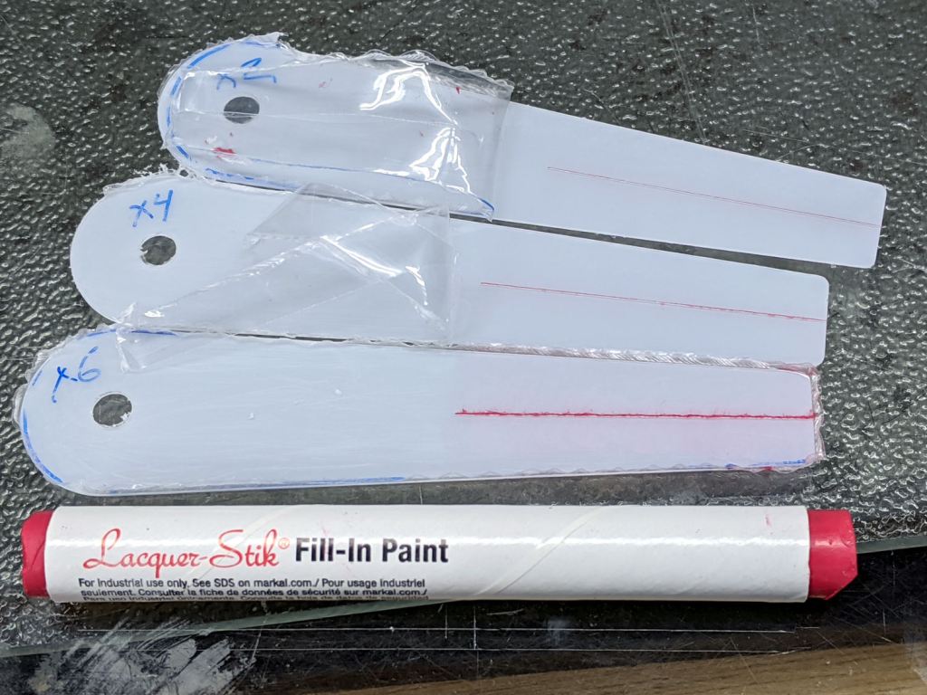
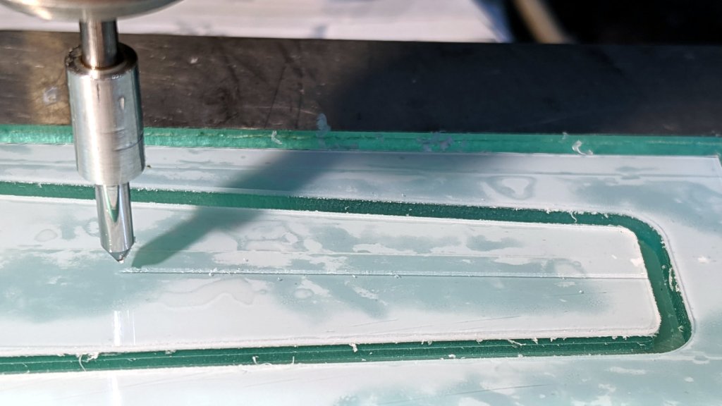
    This time, I diamond-scribed three PETG cursors through the transparent protective film, with two / four / six passes:

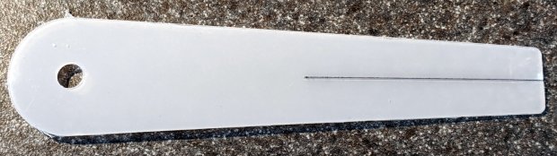
    Tek CC - Cursor hairline filling
    Tek CC – Cursor hairline filling

    It’s not a Purple Crayon, but it suffices for my simple needs.

    Scribbling a (soft!) lacquer crayon over transparent plastic still scuffs the pristine surface around the engraved line, so I tried scribbling the six-pass cursor before peeling the film, as shown above. Unfortunately, the film shreds left around the line either prevent a clean fill or pull the paint out of the ditch as the film peels back:

    Tek CC - Cursor lacquer fill
    Tek CC – Cursor lacquer fill

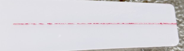
    Peeling the film and scribbling ever-so-gently left a more complete line, but, if you look very closely (perhaps opening the image in a new tab for more dots), you can see the scuffs left by the scribbles on either side of the line:

    Tek CC - Cursor 2 4 6 scribes
    Tek CC – Cursor 2 4 6 scribes

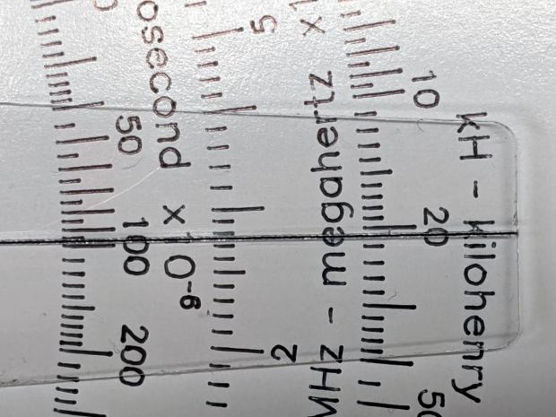
    When seen from the other side against laminated decks, though, the scuffs pretty much vanish:

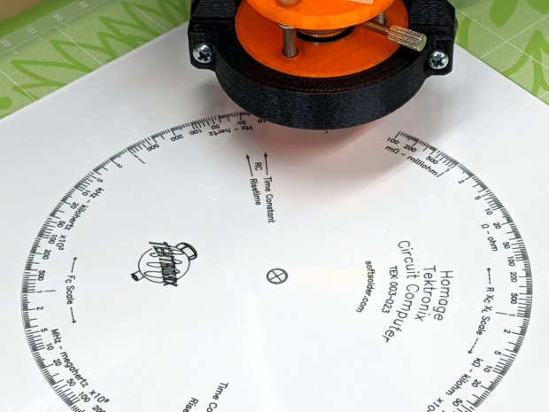
    Tek CC - Classic Tek Logo vectorized - red hairline
    Tek CC – Classic Tek Logo vectorized – red hairline

    The red hairline isn’t historically accurate, but I like the way it looks.

    Give me some (heavyweight matte) paper and a (lacquer) crayon, put me in a basement (shop), and I’ll be happy for days …

  • Vectorized Classic Tektronix Logo

    Vectorized Classic Tektronix Logo

    The Tektronix Circuit Computer sports the most ancient of many Tektronix logos:

    Tek CC Logo - scanned
    Tek CC Logo – scanned

    It’s a bitty thing, with the CRT about 0.7 inch long, scanned directly from my original Tek CC.

    Import the PNG image into FreeCAD at 0.2 mm below the XY plane, resize it upward a smidge so the CRT is maybe 0.8 inch long, then trace “wires” all over it:

    Tek Logo - FreeCAD tracing - overlay
    Tek Logo – FreeCAD tracing – overlay

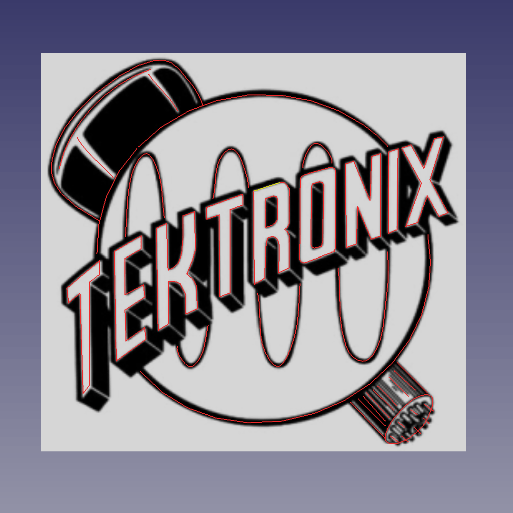
    Given FreeCAD’s default gradient background, the wires definitely don’t stand out by themselves:

    Tek Logo - FreeCAD tracing - vectors
    Tek Logo – FreeCAD tracing – vectors

    Several iterations later, the vectorized logo sits at the correct angle and distance from the origin at the center:

    Tek Logo - FreeCAD tracing - rotated
    Tek Logo – FreeCAD tracing – rotated

    The cheerful colors correspond to various “groups” and make it easier to find errant vectors.

    Rather than figure out how to coerce FreeCAD into converting wires into proper G-Code, export the vectors into a DXF file and slam it into DXF2GCODE:

    Tek Logo - DXF2GCODE vectors
    Tek Logo – DXF2GCODE vectors

    Export as G-Code, iterate around the whole loop a few times to wring out the obvious mistakes, indulge in vigorous yak shaving, eventually decide it’s Good Enough™ for the moment.

    Protip: set DFX2GCODE to put “0” digits before the decimal point to eliminate spaces between the coordinate axes and the numeric values which should not matter in the least, but which confuse NCViewer into ignoring the entire file.

    Tinker the script running the GCMC source code to prepend the logo G-Code to the main file and it all comes out in one run:

    Tek CC - with vectorized logo - cutting
    Tek CC – with vectorized logo – cutting

    That’s the top deck, laminated in plastic, affixed to a Cricut sticky mat on the MPCNC platform, ready for drag-knife cutting.

    Assembled with a snappy red hairline:

    Tek CC - Classic Tek Logo vectorized - red hairline
    Tek CC – Classic Tek Logo vectorized – red hairline

    Isn’t it just the cutest thing you’ve seen in a while?

    It needs more work, but it’s pretty close to right.

  • Tek Circuit Computer: Cursor Fixture Adhesion

    Tek Circuit Computer: Cursor Fixture Adhesion

    After removing debris, flattening the top surface, and generally paying more attention to detail, the PETG sheet has much better adhesion to the fixture:

    Tek CC - Milled cursor - cleaned fixture
    Tek CC – Milled cursor – cleaned fixture

    This time, I traced the inside of a drag-knife cut cursor to extract the blank from the stock and, yes, used new double-sided tape under the lower white protective film on the PETG.

    Fewer air bubbles means better adhesion:

    Tek CC - Milled cursor - fixture adhesion
    Tek CC – Milled cursor – fixture adhesion

    Spinning the 1/8 inch end mill at about 5000 RPM produced finer swarf at the Sherline’s maximum 609 mm/min = 24 inch/min pace, with less uplift. I suspect Moah RPMs! would be even better, constrained by melting the plastic into heartache & confusion.

    Scribe the hairline with the diamond tool, ease the finished cursor off the fixture, scribble Sharpie into the scratch, and wipe

    Tek CC - Milled cursor - second try
    Tek CC – Milled cursor – second try

    It’s Pretty Good™ when seen against an un-laminated bottom deck drawn with a Pilot V5RT pen:

    Tek CC - Milled cursor - unlaminated bottom deck
    Tek CC – Milled cursor – unlaminated bottom deck

    The diamond point tears a slightly gritty path through the PETG, which then looks a bit more granular than a real hairline. I’ve been using four passes for emphasis; perhaps fewer would be better.

  • Tek Circuit Computer: Cursor Milling

    Tek Circuit Computer: Cursor Milling

    The white separating film on the double-sided tape makes the cursor milling fixture look presentable:

    Tek CC - Cursor milling fixture - 2-side tape applied
    Tek CC – Cursor milling fixture – 2-side tape applied

    Some deft X-acto knife work exposed the trench around what will be the cursor’s perimeter, in the hope of keeping tape stickiness out of the milling cutter.

    Peeling off the white film and sticking a PETG cursor blank to the tape reveals I didn’t do a particularly good job of cleaning the rubble from the trench edges:

    Tek CC - Milled cursor - bad tape application
    Tek CC – Milled cursor – bad tape application

    These PETG sheets arrive with a transparent film on one side and a white film on the other. The picture shows the white film on the bottom of the PETG sheet, with the dark areas corresponding to places where the film sticks to the tape and the tape sticks to the fixture. The lighter areas show an air gap in (at least) one of those interfaces; given the amount of clutter, I think it’s mostly between the tape and the fixture.

    I milled the cursor with a 1/8 inch = 3.175 mm cutter:

    Tek CC - Milled cursor - outline
    Tek CC – Milled cursor – outline

    The ball of swarf around the cutter wasn’t as threatening as it appears, because it had very little adhesive holding it together. The rows of swarf surrounding the PETG show why putting the tape all over the fixture isn’t a particularly good idea. ‘Nuff said.

    Engraving the hairline with the diamond drag bit was entirely uneventful:

    Tek CC - Milled cursor - hairline scribe
    Tek CC – Milled cursor – hairline scribe

    Four passes at Z=-2 mm = 300 g downforce put a delicate scratch across the surface. Run a fat black Sharpie along the hairline, wipe off the excess with denatured alcohol, and peel the white film from the other side:

    Tek CC - Milled cursor - first try
    Tek CC – Milled cursor – first try

    It’s sitting atop the doodle giving the dimensions, such as they are, for the milling fixture.

    The hairline came out so fine it makes the Pilot V5RT ballpoint pen lines look downright chunky:

    Tek CC - Yellow Cardstock - Pilot V5RT - Milled Cursor
    Tek CC – Yellow Cardstock – Pilot V5RT – Milled Cursor

    Seen over the engraving test piece with scraped Testors paint, however, things look just the way they should:

    Tek CC - Engraved - Testors Paint - Milled Cursor
    Tek CC – Engraved – Testors Paint – Milled Cursor

    In a techie kind of way, of course, which is the only way that matters on Planet Slipstick …