The Smell of Molten Projects in the Morning

Ed Nisley's Blog: Shop notes, electronics, firmware, machinery, 3D printing, laser cuttery, and curiosities. Contents: 100% human thinking, 0% AI slop.

Tag: CNC

Making parts with mathematics

  • Makergear M2: Z-minimum Switch

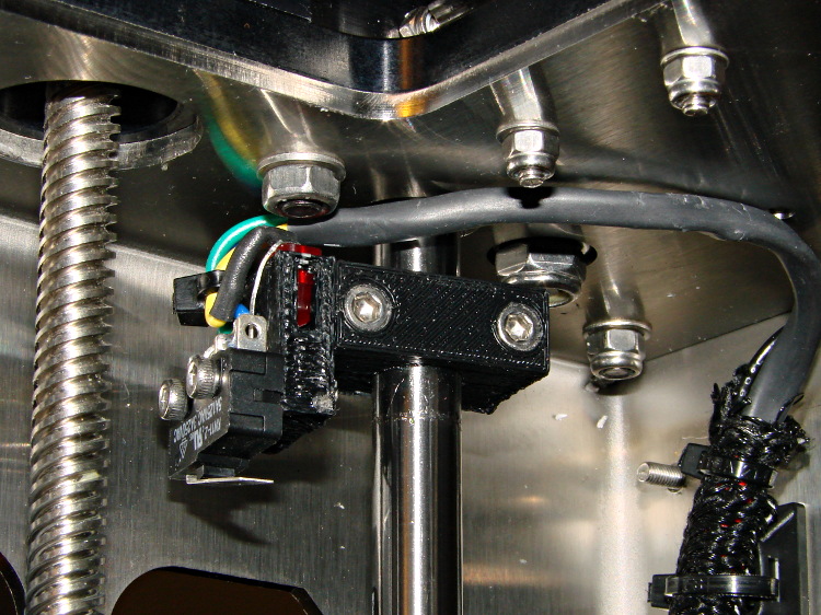
    The best orientation for the Z-minimum switch seems to be slightly angled back:

    M2 - Z min limit switch
    M2 – Z min limit switch

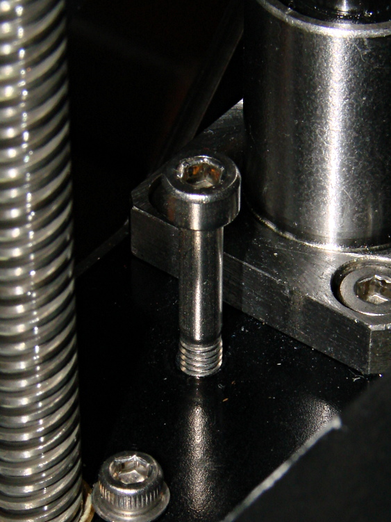
    I used an M4x0.7 socket head cap screw for the height adjustment, with a Nylock nut below the stage:

    M2 - Z min limit screw
    M2 – Z min limit screw

    The assembly instructions show a hex head screw, but the item numbers don’t match the BOM listings. The SHCS lets me hold it firmly in position with the ball-end driver provided in the M2 tool kit while adjusting it:

    • 1/4 turn (the handle is square-ish) = 0.7/4 = 0.175 mm
    • 1/6 turn (the shaft is hex) = 0.12 mm
    • 1/12 turn (you can do it!) = 0.06mm
    • less than that is probably fooling yourself.

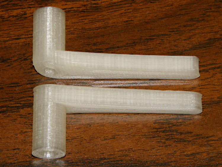
    I printed a pair of tomlombardi’s  7 mm wrenches, which work well for adjusting the Nylock nut underneath the Z axis stage:

    M2 - 7 mm wrenches
    M2 – 7 mm wrenches

    The left end of the top wrench didn’t adhere to the glass plate, but the business end of the wrench came out OK.

    I adjusted the screw to trip the switch with the nozzle 1.0 mm above the platform, then feed that offset in using a G92 Z1.0 instruction in my customized Start G-Code.

    However, the most accurate way to set the switch height involves measuring the as-printed thickness of the skirt extrusion around the object. The average value should be 0.25 mm (for my current slic3r settings, anyhow) and all sides should be equally thick: adjust the screw to change the average and adjust the platform screws to remove any tilt. You’ll quickly accumulate a pile of skirt threads, but they make good tchotchkes when you give a presentation on your new toy:

    M2 skirt extrusions
    M2 skirt extrusions

    You could fiddle with the G92 value to make the average thickness come out right, but I favor making the machine as accurate as possible, so that the software begins from a known-good mechanical setting.

  • Makergear M2: Pronterface Configuration

    I use Kliment’s Pronterface for printer control: simplicity with enough knobs.

    The .pronsolerc file:

    set port /dev/ttyACM0
    set baudrate 115200
    set build_dimensions 200x240x195-100-120+0
    set temperature_abs 200
    set last_bed_temperature 70.0
    set last_temperature 155.0
    set xy_feedrate 30000
    set z_feedrate 2500
    set e_feedrate 300
    set last_file_path /mnt/bulkdata/Project Files/Thing-O-Matic/Calibration
    set temperature_pla 165
    set preview_grid_step1 10
    set preview_grid_step2 20.0
    set preview_extrusion_width 0.4
    set bedtemp_pla 70


    Line 3 sizes the preview and offsets the XY=0 origin to the center of the plot.

    The 200 mm X axis dimension is slightly larger than the actual 195 mm buildable area on the platform, but if the object gets that close to the maximum size, this isn’t the place to discover it.

    The 240 mm Y axis dimension is slightly shorter than the actual 250 mm buildable area and slightly larger than the distance between the snouts of the bulldog clips holding the glass plate to the heater. In this case, the object can slightly exceed the preview size if it fits between the clips.

    Lines 12 and 13 produce a relatively coarse grid that’s both meaningful and easy on the eyes, with the XY dimensions in Line 3 producing a major grid line crossing at the origin where it should be:

    M2 Pronterface - screen shot
    M2 Pronterface – screen shot
  • Makergear M2: Post and Hole Calibration Test Objects

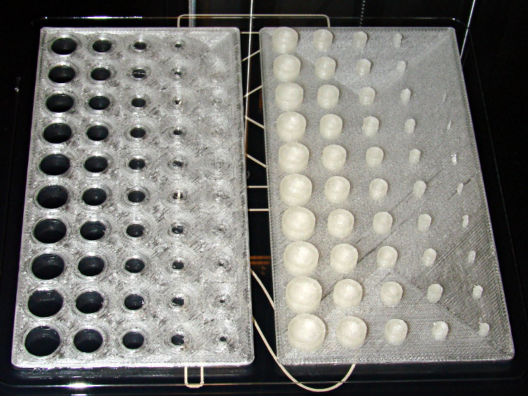
    Despite the profusion of surface-finish and print quality test objects, I really care about the dimensions of a 3D printed object, because I tend to build widgets rather than art objects. These two objects, from walter’s Hole and Column Test Print, produce calibrated holes and columns from 0.20 mm to 10.00 mm in diameter, incrementing by 0.20 mm, that should slip neatly together:

    M2 - walter hole-column test
    M2 – walter hole-column test

    Of course, they didn’t, but they came surprisingly close for a first attempt.

    The 0.20 and 0.40 posts simply aren’t there, because they’re too small to print with a 0.35 mm diameter nozzle. The 0.60 through 1.40 mm posts were present, albeit fugly, and posts larger than that looked increasingly better.

    Although all the holes were present, in the sense that you could see a disturbance in the top and bottom infill pattern, the first visibly open hole appeared at the 0.80 mm spot… and it was immeasurably small. Some holes had misplaced perimeter strands stretching across the openings, which is probably due to excessive speed from my fiddling around with the numbers.

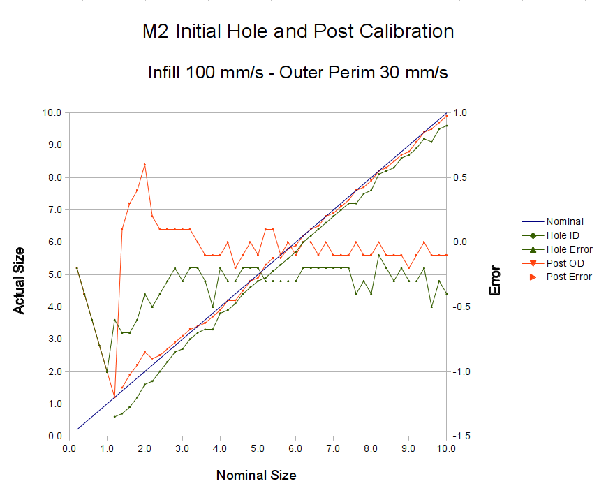
    Measuring them with a digital caliper, with no effort at finding the best orientation, then slapping the data into a Libreoffice spreadsheet, produces an interesting graph:

    M2 - Initial Hole and Post Diameter Calibration
    M2 – Initial Hole and Post Diameter Calibration

    Above about 3 mm diameter: posts are 0.1 mm too small and holes are 0.3 mm too small. Around 2 mm, posts are too big and holes are way too small. What’s important: above maybe 2.5 mm, the error is essentially constant and does not scale with diameter, so a simple Finagle Constant (or two) can solve (most of) the problem.

    Some experiments involving slic3r’s small-perimeter speed seem in order; it was 25 mm/s for these pieces.

    More care in measurement would produce better answers, but the real question is whether you can produce holes and columns with known sizes; the answer (as expected) remains “with some care”. That’s not surprising; I expect to have an M2 + PLA version of the small hole diameter Finagle Constant that I’ve been using with Skeinforge + Thing-O-Matic; the correction will certainly fall in the same ballpark.

    The slic3r configuration:

    ; generated by Slic3r 0.9.8 on 2013-04-01 at 16:20:49
    
    ; layer_height = 0.25
    ; perimeters = 1
    ; top_solid_layers = 3
    ; bottom_solid_layers = 3
    ; fill_density = 0.10
    ; perimeter_speed = 100
    ; infill_speed = 300
    ; travel_speed = 500
    ; scale = 1
    ; nozzle_diameter = 0.35
    ; filament_diameter = 1.70
    ; extrusion_multiplier = 0.9
    ; perimeters extrusion width = 0.40mm
    ; infill extrusion width = 0.40mm
    ; first layer extrusion width = 0.39mm
    

    The source code comes from the Thingiverse customizer as bare G-Code, so there’s not much point in reproducing it here.

  • Makergear M2: Fundamental Test Object

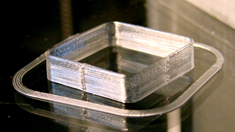
    Building these things seems to be the simplest and best way to figure out whether you have all the pieces flying in formation:

    Thinwall box - first success
    Thinwall box – first success

    I took that picture after cracking them off the glass plate, then putting them back: the box really does line up with the skirt while printing. There’s another object visible in the background; that little box really was the first completely successful object.

    It’s adapted from Coasterman’s classic calibration set, redone in OpenSCAD so it’s easy to modify. A pair of Minkowski sums produce two shapes that ensure the wall remains exactly one thread wide all the way around the perimeter.

    [Update: The revised version works better.]

    When your printer can print one of these, then you can move on to more complex objects, secure in the knowledge that you’ve established:

    • Proper bed leveling and height setting: measure the skirt thickness
    • Both the layer thickness and width match your settings
    • Extrusion temperature: not too hot, not too cold
    • Printing speed / acceleration for all layers
    • First layer adhesion to platform
    • Minimum layer time to prevent melting / slumping
    • Filament diameter
    • Extrusion “packing density” multiplier: the fundamental fudge factor
    • Accurate steps/mm for all axes to get exact XYZ dimensions
    • Mechanical stability and rigidity

    Basically, this object leaves no place for errors to hide. It doesn’t check infill, the various perimeter speeds, solid layers, and suchlike, but all the fundamentals must be correct or you’ll see painfully obvious flaws.

    For example, there’s a bit of a zipper at the layer changes. It’s better than the Thing-O-Matic ever was, but it improved as I twiddled the Retraction settings on later objects.

    No, the first few didn’t work quite that well:

    M2 - Thinwall box with previous attempts
    M2 – Thinwall box with previous attempts

    For what it’s worth, the last problem turned out to be a loose setscrew in the X axis motor pulley that produced a layer shift that closely resembled a stepper motor losing steps. All of the setscrews now sport a dab of low-strength Loctite, so that problem shouldn’t happen again.

    Yes, I did the happy dance…

    The slic3r header:

    ; generated by Slic3r 0.9.8 on 2013-03-26 at 11:01:10
    
    ; layer_height = 0.25
    ; perimeters = 1
    ; top_solid_layers = 3
    ; bottom_solid_layers = 3
    ; fill_density = 0.20
    ; perimeter_speed = 100
    ; infill_speed = 150
    ; travel_speed = 500
    ; scale = 1
    ; nozzle_diameter = 0.35
    ; filament_diameter = 1.70
    ; extrusion_multiplier = 0.9
    ; perimeters extrusion width = 0.40mm
    ; infill extrusion width = 0.40mm
    ; first layer extrusion width = 0.39mm
    

    The solid model has no surprises:

    Thinwall Open Box - solid model
    Thinwall Open Box – solid model

    The OpenSCAD source code:

    // Thin wall open box calibration piece
    // Adapted from Coasterman's Calibration set
    // Ed Nisley - KE4ZNU - Dec 2011
    // Adjust for Slic3r/M2 - March 2013
    
    //-------
    //- Extrusion parameters must match reality!
    //  None of the fill parameters matter
    
    ThreadThick = 0.25;
    ThreadWidth = 0.40;
    
    Protrusion = 0.1;           // make holes end cleanly
    
    function IntegerMultiple(Size,Unit) = Unit * ceil(Size / Unit);
    
    //-------
    // Dimensions
    
    Height = IntegerMultiple(5.0,ThreadThick);
    
    WallThick = ThreadWidth;
    
    CornerRadius = 2.0;
    CornerSides = 4*8;
    
    SideLen = 20.0 - 2*CornerRadius;
    
    Rotation = 45;
    
    //-------
    
    module ShowPegGrid(Space = 10.0,Size = 1.0) {
    
    Range = floor(50 / Space);
    
    for (x=[-Range:Range])
    for (y=[-Range:Range])
    translate([x*Space,y*Space,Size/2])
    %cube(Size,center=true);
    }
    
    //-------
    
    ShowPegGrid();
    
    rotate(Rotation)
    translate([0,0,Height/2])
    intersection() {
    difference() {
    minkowski() {
    cube([SideLen,SideLen,Height],center=true);
    cylinder(r=CornerRadius,h=Protrusion,$fn=CornerSides);
    }
    minkowski() {
    cube([(SideLen - 2*WallThick),(SideLen - 2*WallThick),2*Height],center=true);
    cylinder(r=CornerRadius,h=Protrusion,$fn=CornerSides);
    }
    }
    cube([2*SideLen,2*SideLen,Height],center=true);
    }
    

    [Update: You should use the code from the revised version.]

  • Makergear M2: Z Axis Numbers

    Now that I understand why the M2 Z axis stepper gets so hot, the question is: does it matter?

    The Z axis stage moves very smoothly along the two guide rails, so there’s little friction and no binding involved. I can’t weigh the thing without dismantling the whole printer, which isn’t going to happen right now, but some crude experiments indicate that 7 pounds = 3 kgf = 30 N isn’t too far from the truth.

    The 8 mm OD leadscrew has a 4-start thread at 3.25 turn/inch = 0.311 inch/turn = 0.13 turn/mm = 7.8 mm/turn.

    [Update: Thanks to Jetguy for pointing out the blindingly obvious fact that it’s really 8 mm/turn = 0.125 turn/mm and you can do the inch conversion yourself if you need it. That doesn’t materially affect the results, given that they have about one significant figure of accuracy to start with.]

    The firmware uses 1/16 microstepping at 400 step/mm = 3077 3200 step/turn.

    Using a pull scale to, yes, pull a string wound around the knob on the Z axis leadscrew shows about 1 pound raises the platform at a slow, constant speed. The polygonal knob is about 35 mm in diameter, so the torque works out to 11 ounce·inch = 80 mN·m. Presumably, holding the platform at a given position would require somewhat less torque, but I can’t measure that with any confidence.

    The motor has very little excess torque: a gentle touch can stall the Z axis motor as it raises the stage. I guesstimate the motor produces 150 mN·m, tops, during low-speed motion at 600 mA.

    Lowering the stage requires no effort at all: it falls under its own weight, prompting me to install those bumpers. The design doesn’t have much compliance, but it’s well-adjusted and works fine.

    Searching with the appropriate keywords produces a 17HD-B8X300-H motor from Kysan:

    • 12 V
    • 400 mA
    • 30 Ω
    • 42 mH
    • 2.6 kg·cm = 260 mN·m

    That’s a close-enough match to suggest my measurements are in the right ballpark. The extremely high resistance and inductance indicate this is the wrong motor for a high-performance microstepping application.

    The firmware has DEFAULT_MAX_ACCELERATION = 30 mm/s2 for the Z axis. It’s 9000 for X and Y, 10000 for the extruder. The extremely low Z acceleration says there’s something badly wrong with this setup.

    There is also a DEFAULT_ACCELERATION = 3000 for all axes. I don’t know how that interacts with the per-axis limit, but I’m certain the Z axis doesn’t come close to that value.

    I do not know how the firmware actually handles motor steps while ramping up and down, but I do intend to clamp a current probe around a motor wire and measure what goes on. Let us assume it works in the usual way all ideal components behave in physics labs.

    Assuming a constant 30 mm/s2 acceleration for the first half of a 0.25 mm Z axis move, the time should be:

    0.25 / 2 = (1/2) * 30 * t2
    t = 90 ms

    At the end of that ramp-up, the Z stage will be trundling along at:

    v2 = 2 * 30 * 0.25/2
    v = 2.8 mm/s

    The move requires exactly 50 steps = 0.25/2 mm * 400 step/mm.

    Assuming the same deceleration during the second half of the move, a 0.25 mm layer change requires about twice that long: 180 ms for 100 steps.

    Along the X axis, a 0.25/2 mm move requires 5.3 ms and reaches a peak speed of 47 mm/s. The total move requires 11 ms and 22.22 steps (= 0.25 mm * 88.88 step/mm, obviously rounded to 22).

    I think a difference of more than an order of magnitude matters, although some actual measurements are definitely appropriate.
  • Makergear M2: Z-axis Stepper Motor

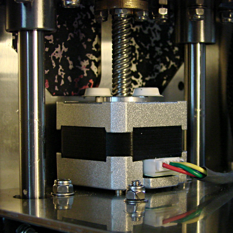
    Several users have observed that the stepper motor driving the M2’s Z axis leadscrew gets very hot. I measured about 140 °F = 60 °C on the as-built motor, so I loosened the screws and raised the motor slightly:

    M2 Z axis motor - raised
    M2 Z axis motor – raised

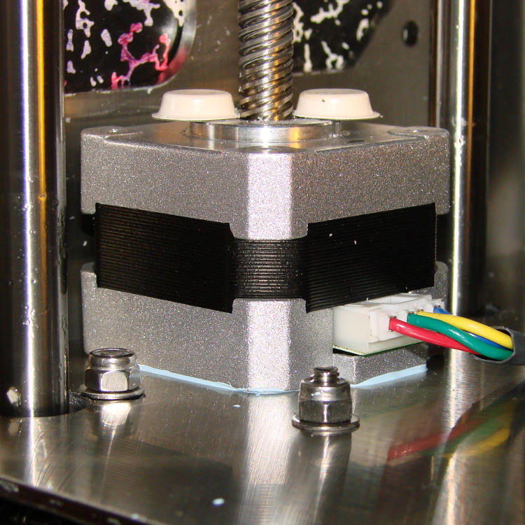
    I eased some heatsink compound underneath by putting dabs on a slip of paper and painting it on the bottom of the motor case, lowered the Z stage to the bottom of its travel, and tightened the mounting screws:

    M2 Z axis motor - added thermal compound
    M2 Z axis motor – added thermal compound

    That reduced the temperature to about 120 °F = 50 °C, which still seemed excessive for a short-stack motor mounted on a fairly large chunk of stainless steel. The motor also sounded quite rough during homing and long manual moves, sooo … something was wrong. I bet you know where this is going, right?

    Let’s start with the firmware side and determine what current the motor should be seeing.

    The M2 uses a slightly modified version of the Marlin firmware running on a RAMBo 1.1b board. The basic RAMBo doc gives these equations relating the peak winding current Imax to the constant W that defines it in the firmware:

    Vref = 0.8 * Imax
    W = 255 * (Vref / 1.66)

    Mashing those together produces this:

    W = 255 * (0.8 * Imax) / 1.66

    The default Z axis stepper current constant W (called Z_CURRENT in the Marlin source) is 135. The board in my M2 has R30 = 3.3 kΩ, which sets the maximum possible current to 2 A. Working the equation backwards, a Z_CURRENT = 135 will produce a peak winding current of 1.1 A.

    However, a nearby comment in the source code suggests this is should be about 0.75 A. The original RAMBo board had a maximum possible current of 1.5 A, but running those numbers doesn’t agree. Another comment suggests 185 corresponds to about 1 A, which isn’t right, either. There’s nothing new about stale comments not corresponding to the actual hardware; I’ve done that myself.

    With 1.1 A in hand, let’s unplug the cable and measure the winding resistance.

    Not much to my surprise, the motor has 28 Ω windings. The M2 uses a 19 V supply for the steppers, so the maximum motor current works out to 19 V/28 Ω  = 680 mA, but it must be less than that to allow the microstepping controller to manage the current.

    It seems that Makergear is connecting a high-resistance stepper intended for a simple H-bridge drive to a high-performance microstepping controller. For some background on why that combination doesn’t work, see my analysis of the original MBI Thing-O-Matic steppers.

    I thought we all agreed we weren’t going to do that any more. Maybe nobody sells a low-resistance motor-with-integral-leadscrew?

    Anyhow.

    The only thing to do in the short term is to reduce the peak current to a rational value around 600 mA:

    74 = 255 * (0.8 * 0.6) / 166

    I set it to a nice, round 75 and reloaded the firmware, which immediately made the motor hum, rather than growl, on long moves. The case temperature didn’t drop by very much, because the poor motor still dissipates about 11 W, not much less than the original 13 W. There’s only so much heat you can pull out of the case and these little motors are actually rated for maybe 5 W, tops.

    The motor’s overall performance didn’t change, which is good, because it didn’t have much performance to begin with. The X and Y motors can accelerate at 9000 mm/s2, but the Z motor limit is 30 mm/s2; it doesn’t really accelerate, it sort of gains momentum in a stately manner.

    Next: let’s see if it really matters.

  • Makergear M2 vs. LinuxCNC: Project Overview

    M2 - cushwa Owl - half scale
    M2 – cushwa Owl – half scale

    During the course of my Makerbot Thing-O-Matic experience, I concluded:

    • Enthusiasm may get a product out, but engineering makes it work
    • Plywood and plastic do not produce a stable 3D printer
    • Measurements matter
    • 8-bit microcontrollers belong in the dustbin of history

    With that in mind, I’ve long thought that LinuxCNC (formerly EMC2) would provide a much better basis for the control software required for a 3D printer than the current crop of Arduino-based microcontrollers. LinuxCNC provides:

    • Hard real time motion control with proven performance
    • A robust, well-defined hardware interface layer
    • Ladder-logic machine control
    • Isolated userspace programming
    • Access to a complete Linux distro’s wealth of programs / utilities
    • Access to an x86 PC’s wealth of hardware gadgetry

    Rather than (try to) force-fit new functions in an Arduino microcontroller, I decided it would be interesting to retrofit a DIY 3D printer with a LinuxCNC controller, improve the basic hardware control and sensing, instrument the extruder, then take measurements that might shed some light on DIY 3D printing’s current shortcomings.

    The overall plan looks like this:

    • Start with a Makergear M2
    • See what the stock hardware can do
    • Replace the RAMBo controller with LinuxCNC
    • See what the hardware can do with better drivers
    • Adapt the G-Code / M-Code processing to use more-or-less stock Marlin G-Code
    • Add useful controllers along the lines of the Joggy Thing
    • Improve the platform height / level sensing
    • Rebuild the extruder with temperature and force sensors
    • Start taking measurements!

    My reasons for choosing the Makergear M2 as the basis for this project should be obvious:

    • All metal: no plywood, no acrylic (albeit a plastic filament drive)
    • Decent stepper motors (with one notable exception)
    • Reasonable hot end design
    • Good reputation

    The first step of the overall plan included a meticulously documented M2 build that I figured would take a month or two, what with the usual snafus and gotchas that accompany building any complex mechanism. Quite by coincidence, a huge box arrived on my birthday (the Thing-O-Matic arrived on Christmas Eve, so perhaps this is a tradition), the day when I learned that Mad Phil had entered his final weeks of life.

    As the Yiddish proverb puts it: If you wish to hear G*d laugh, tell him of your plans.

    So I converted a box of parts into a functional M2 3D printer over the course of four intense days, alternating between our living room floor and a card table in Phil’s home office, showing him how things worked, getting his advice & suggestions, and swapping “Do you remember when?” stories. Another few days sufficed for software installation, configuration, and basic tuneup; I managed to show him some shiny plastic doodads just before he departed consensus reality; as nearly as I can tell, we both benefited from the distractions.

    Which means I don’t have many pictures or much documentation of the in-process tweakage that produced a functional printer. The next week or so of posts should cover the key points in enough detail to be useful.

    Not to spoil the plot or anything: a stock M2 works wonderfully well.

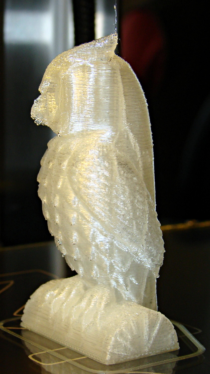
    Owl - half size - left
    Owl – half size – left

    For example, a half-scale cushwa owl printed in PLA at 165 °C with no bed cooling and these Slic3r parameters:

    • 500 mm/s move
    • 300 mm/s infill
    • 200 mm/s solid infill
    • 100 mm/s internal perimeter
    • 50 mm/s bottom layer
    • 30 mm/s external perimeter
    • 1 mm retract @ 300 mm/s

    The beak came out slightly droopy and each downward-pointing feather dangles a glittery drop. There’s room for improvement, but that’s pretty good a week after opening a box o’ parts…