The Smell of Molten Projects in the Morning

Ed Nisley's Blog: Shop notes, electronics, firmware, machinery, 3D printing, laser cuttery, and curiosities. Contents: 100% human thinking, 0% AI slop.

Tag: CNC

Making parts with mathematics

  • TC4Server: Eagle HAL Device

    Dan Newman’s TC4Server turns the TC4 thermocouple board into a USB HID input device that’s compatible with HAL’s hal_input module:

    TC4 on ProtoScrewShield on Leonardo
    TC4 on ProtoScrewShield on Leonardo

    For simplicity (i.e., to avoid writing a special driver), TC4Server misrepresents itself as a nine-axis joystick-like device suited for RC airplane control:

    halrun
    halcmd: loadusr -W hal_input +A Leonardo
    halcmd: show
    ... snippage ...
    Component Pins:
    Owner   Type  Dir         Value  Name
         5  s32   OUT          2941  input.0.abs-rudder-counts
         5  s32   IN           4095  input.0.abs-rudder-flat
         5  s32   IN            255  input.0.abs-rudder-fuzz
         5  bit   OUT          TRUE  input.0.abs-rudder-is-neg
         5  bit   OUT         FALSE  input.0.abs-rudder-is-pos
         5  float IN        32767.5  input.0.abs-rudder-offset
         5  float OUT    -0.9102464  input.0.abs-rudder-position
         5  float IN        32767.5  input.0.abs-rudder-scale
         5  s32   OUT          2947  input.0.abs-rx-counts
         5  s32   IN           4095  input.0.abs-rx-flat
         5  s32   IN            255  input.0.abs-rx-fuzz
         5  bit   OUT          TRUE  input.0.abs-rx-is-neg
         5  bit   OUT         FALSE  input.0.abs-rx-is-pos
         5  float IN        32767.5  input.0.abs-rx-offset
         5  float OUT    -0.9100633  input.0.abs-rx-position
         5  float IN        32767.5  input.0.abs-rx-scale
         5  s32   OUT         65535  input.0.abs-ry-counts
         5  s32   IN           4095  input.0.abs-ry-flat
         5  s32   IN            255  input.0.abs-ry-fuzz
         5  bit   OUT         FALSE  input.0.abs-ry-is-neg
         5  bit   OUT          TRUE  input.0.abs-ry-is-pos
         5  float IN        32767.5  input.0.abs-ry-offset
         5  float OUT             1  input.0.abs-ry-position
         5  float IN        32767.5  input.0.abs-ry-scale
         5  s32   OUT         65535  input.0.abs-rz-counts
         5  s32   IN           4095  input.0.abs-rz-flat
         5  s32   IN            255  input.0.abs-rz-fuzz
         5  bit   OUT         FALSE  input.0.abs-rz-is-neg
         5  bit   OUT          TRUE  input.0.abs-rz-is-pos
         5  float IN        32767.5  input.0.abs-rz-offset
         5  float OUT             1  input.0.abs-rz-position
         5  float IN        32767.5  input.0.abs-rz-scale
         5  s32   OUT         65535  input.0.abs-throttle-counts
         5  s32   IN           4095  input.0.abs-throttle-flat
         5  s32   IN            255  input.0.abs-throttle-fuzz
         5  bit   OUT         FALSE  input.0.abs-throttle-is-neg
         5  bit   OUT          TRUE  input.0.abs-throttle-is-pos
         5  float IN        32767.5  input.0.abs-throttle-offset
         5  float OUT             1  input.0.abs-throttle-position
         5  float IN        32767.5  input.0.abs-throttle-scale
         5  s32   OUT          2957  input.0.abs-wheel-counts
         5  s32   IN           4095  input.0.abs-wheel-flat
         5  s32   IN            255  input.0.abs-wheel-fuzz
         5  bit   OUT          TRUE  input.0.abs-wheel-is-neg
         5  bit   OUT         FALSE  input.0.abs-wheel-is-pos
         5  float IN        32767.5  input.0.abs-wheel-offset
         5  float OUT    -0.9097581  input.0.abs-wheel-position
         5  float IN        32767.5  input.0.abs-wheel-scale
         5  s32   OUT          2942  input.0.abs-x-counts
         5  s32   IN           4095  input.0.abs-x-flat
         5  s32   IN            255  input.0.abs-x-fuzz
         5  bit   OUT          TRUE  input.0.abs-x-is-neg
         5  bit   OUT         FALSE  input.0.abs-x-is-pos
         5  float IN        32767.5  input.0.abs-x-offset
         5  float OUT    -0.9102159  input.0.abs-x-position
         5  float IN        32767.5  input.0.abs-x-scale
         5  s32   OUT          2942  input.0.abs-y-counts
         5  s32   IN           4095  input.0.abs-y-flat
         5  s32   IN            255  input.0.abs-y-fuzz
         5  bit   OUT          TRUE  input.0.abs-y-is-neg
         5  bit   OUT         FALSE  input.0.abs-y-is-pos
         5  float IN        32767.5  input.0.abs-y-offset
         5  float OUT    -0.9102159  input.0.abs-y-position
         5  float IN        32767.5  input.0.abs-y-scale
         5  s32   OUT          2940  input.0.abs-z-counts
         5  s32   IN           4095  input.0.abs-z-flat
         5  s32   IN            255  input.0.abs-z-fuzz
         5  bit   OUT          TRUE  input.0.abs-z-is-neg
         5  bit   OUT         FALSE  input.0.abs-z-is-pos
         5  float IN        32767.5  input.0.abs-z-offset
         5  float OUT     -0.910277  input.0.abs-z-position
         5  float IN        32767.5  input.0.abs-z-scale
         5  s32   OUT          2941  input.1.abs-rudder-counts
         5  s32   IN           4095  input.1.abs-rudder-flat
         5  s32   IN            255  input.1.abs-rudder-fuzz
         5  bit   OUT          TRUE  input.1.abs-rudder-is-neg
         5  bit   OUT         FALSE  input.1.abs-rudder-is-pos
         5  float IN        32767.5  input.1.abs-rudder-offset
         5  float OUT    -0.9102464  input.1.abs-rudder-position
         5  float IN        32767.5  input.1.abs-rudder-scale
         5  s32   OUT          2947  input.1.abs-rx-counts
         5  s32   IN           4095  input.1.abs-rx-flat
         5  s32   IN            255  input.1.abs-rx-fuzz
         5  bit   OUT          TRUE  input.1.abs-rx-is-neg
         5  bit   OUT         FALSE  input.1.abs-rx-is-pos
         5  float IN        32767.5  input.1.abs-rx-offset
         5  float OUT    -0.9100633  input.1.abs-rx-position
         5  float IN        32767.5  input.1.abs-rx-scale
         5  s32   OUT         65535  input.1.abs-ry-counts
         5  s32   IN           4095  input.1.abs-ry-flat
         5  s32   IN            255  input.1.abs-ry-fuzz
         5  bit   OUT         FALSE  input.1.abs-ry-is-neg
         5  bit   OUT          TRUE  input.1.abs-ry-is-pos
         5  float IN        32767.5  input.1.abs-ry-offset
         5  float OUT             1  input.1.abs-ry-position
         5  float IN        32767.5  input.1.abs-ry-scale
         5  s32   OUT         65535  input.1.abs-rz-counts
         5  s32   IN           4095  input.1.abs-rz-flat
         5  s32   IN            255  input.1.abs-rz-fuzz
         5  bit   OUT         FALSE  input.1.abs-rz-is-neg
         5  bit   OUT          TRUE  input.1.abs-rz-is-pos
         5  float IN        32767.5  input.1.abs-rz-offset
         5  float OUT             1  input.1.abs-rz-position
         5  float IN        32767.5  input.1.abs-rz-scale
         5  s32   OUT         65535  input.1.abs-throttle-counts
         5  s32   IN           4095  input.1.abs-throttle-flat
         5  s32   IN            255  input.1.abs-throttle-fuzz
         5  bit   OUT         FALSE  input.1.abs-throttle-is-neg
         5  bit   OUT          TRUE  input.1.abs-throttle-is-pos
         5  float IN        32767.5  input.1.abs-throttle-offset
         5  float OUT             1  input.1.abs-throttle-position
         5  float IN        32767.5  input.1.abs-throttle-scale
         5  s32   OUT          2957  input.1.abs-wheel-counts
         5  s32   IN           4095  input.1.abs-wheel-flat
         5  s32   IN            255  input.1.abs-wheel-fuzz
         5  bit   OUT          TRUE  input.1.abs-wheel-is-neg
         5  bit   OUT         FALSE  input.1.abs-wheel-is-pos
         5  float IN        32767.5  input.1.abs-wheel-offset
         5  float OUT    -0.9097581  input.1.abs-wheel-position
         5  float IN        32767.5  input.1.abs-wheel-scale
         5  s32   OUT          2942  input.1.abs-x-counts
         5  s32   IN           4095  input.1.abs-x-flat
         5  s32   IN            255  input.1.abs-x-fuzz
         5  bit   OUT          TRUE  input.1.abs-x-is-neg
         5  bit   OUT         FALSE  input.1.abs-x-is-pos
         5  float IN        32767.5  input.1.abs-x-offset
         5  float OUT    -0.9102159  input.1.abs-x-position
         5  float IN        32767.5  input.1.abs-x-scale
         5  s32   OUT          2942  input.1.abs-y-counts
         5  s32   IN           4095  input.1.abs-y-flat
         5  s32   IN            255  input.1.abs-y-fuzz
         5  bit   OUT          TRUE  input.1.abs-y-is-neg
         5  bit   OUT         FALSE  input.1.abs-y-is-pos
         5  float IN        32767.5  input.1.abs-y-offset
         5  float OUT    -0.9102159  input.1.abs-y-position
         5  float IN        32767.5  input.1.abs-y-scale
         5  s32   OUT          2940  input.1.abs-z-counts
         5  s32   IN           4095  input.1.abs-z-flat
         5  s32   IN            255  input.1.abs-z-fuzz
         5  bit   OUT          TRUE  input.1.abs-z-is-neg
         5  bit   OUT         FALSE  input.1.abs-z-is-pos
         5  float IN        32767.5  input.1.abs-z-offset
         5  float OUT     -0.910277  input.1.abs-z-position
         5  float IN        32767.5  input.1.abs-z-scale
    
    ... snippage ...
    Parameters:
    Owner   Type  Dir         Value  Name
         5  s32   RO          65535  input.0.abs-rudder-max
         5  s32   RO              0  input.0.abs-rudder-min
         5  s32   RO          65535  input.0.abs-rx-max
         5  s32   RO              0  input.0.abs-rx-min
         5  s32   RO          65535  input.0.abs-ry-max
         5  s32   RO              0  input.0.abs-ry-min
         5  s32   RO          65535  input.0.abs-rz-max
         5  s32   RO              0  input.0.abs-rz-min
         5  s32   RO          65535  input.0.abs-throttle-max
         5  s32   RO              0  input.0.abs-throttle-min
         5  s32   RO          65535  input.0.abs-wheel-max
         5  s32   RO              0  input.0.abs-wheel-min
         5  s32   RO          65535  input.0.abs-x-max
         5  s32   RO              0  input.0.abs-x-min
         5  s32   RO          65535  input.0.abs-y-max
         5  s32   RO              0  input.0.abs-y-min
         5  s32   RO          65535  input.0.abs-z-max
         5  s32   RO              0  input.0.abs-z-min
         5  s32   RO          65535  input.1.abs-rudder-max
         5  s32   RO              0  input.1.abs-rudder-min
         5  s32   RO          65535  input.1.abs-rx-max
         5  s32   RO              0  input.1.abs-rx-min
         5  s32   RO          65535  input.1.abs-ry-max
         5  s32   RO              0  input.1.abs-ry-min
         5  s32   RO          65535  input.1.abs-rz-max
         5  s32   RO              0  input.1.abs-rz-min
         5  s32   RO          65535  input.1.abs-throttle-max
         5  s32   RO              0  input.1.abs-throttle-min
         5  s32   RO          65535  input.1.abs-wheel-max
         5  s32   RO              0  input.1.abs-wheel-min
         5  s32   RO          65535  input.1.abs-x-max
         5  s32   RO              0  input.1.abs-x-min
         5  s32   RO          65535  input.1.abs-y-max
         5  s32   RO              0  input.1.abs-y-min
         5  s32   RO          65535  input.1.abs-z-max
         5  s32   RO              0  input.1.abs-z-min
    ... snippage ...
    

    Dan’s program assigns the outputs thusly:

    • Wheel – ambient temperature as measured on TC4 board
    • X Y Z Rudder – thermocouples – channels 1 through 4
    • RX RY RZ  Throttle – thermistors – channels 5 through 8

    I created a huge Eagle device that encapsulates the whole thing. A simple demo schematic includes the constants that make the temperatures come out in °C:
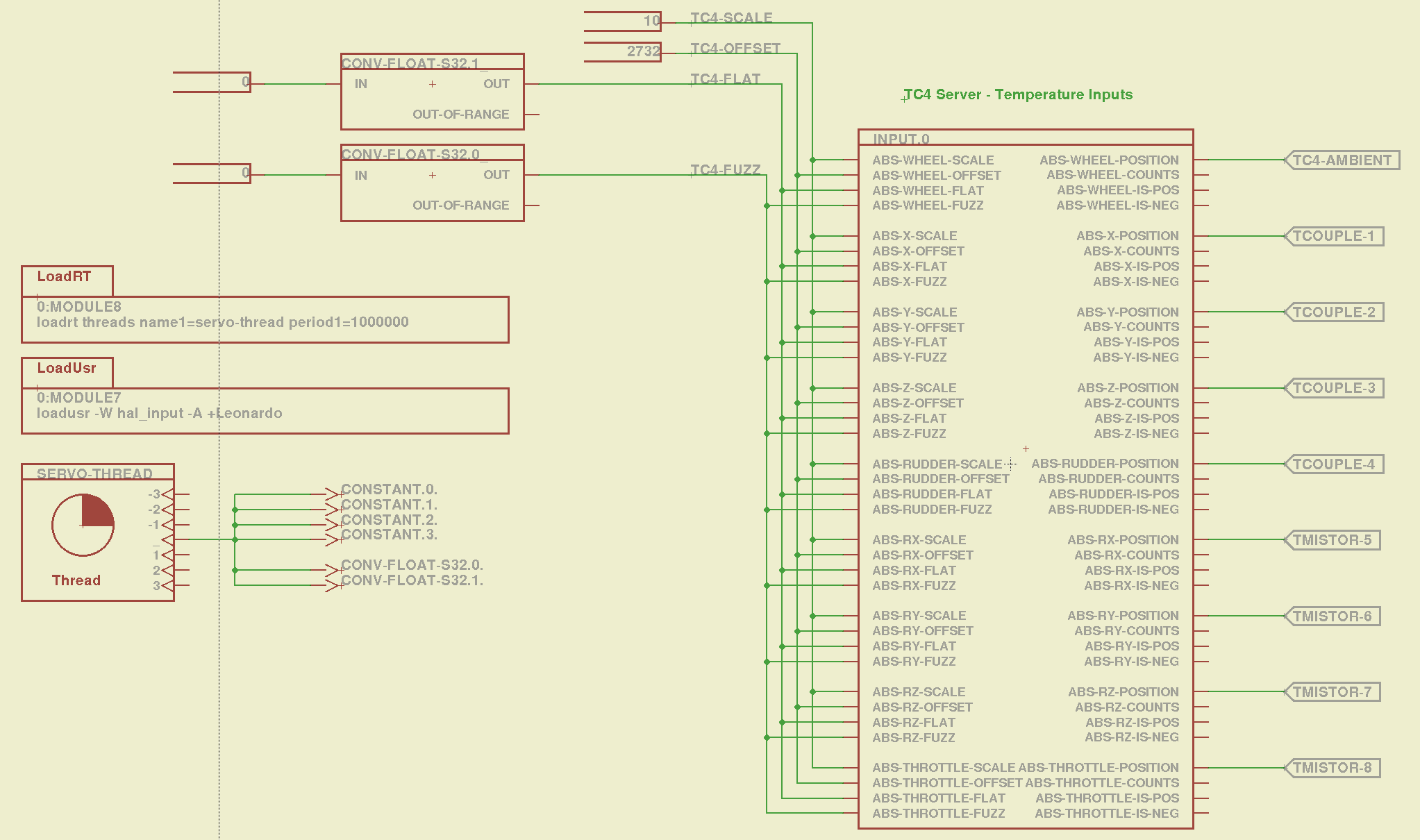
    TC4Server - Eagle Schematic
    TC4Server – Eagle Schematic

    That picture produces this HAL file:

    # HAL config file automatically generated by Eagle-CAD ULP:
    # [/mnt/bulkdata/Project Files/eagle/ulp/hal-write-2.5.ulp]
    # (C) Martin Schoeneck.de 2008
    # Charalampos Alexopoulos 2011
    # Mods Ed Nisley KE4ZNU 2010 2013
    # Path        [/mnt/bulkdata/Project Files/eagle/projects/LinuxCNC for M2/]
    # ProjectName [LinuxCNC M2 - TC4Server Test]
    # File name   [/mnt/bulkdata/Project Files/eagle/projects/LinuxCNC for M2/TC4Server.hal]
    # Created     [20:03:16 03-Jun-2013]
    
    ####################################################
    # Load realtime and userspace modules
    loadusr -W hal_input -A +Leonardo
    loadrt threads name1=servo-thread period1=1000000
    loadrt constant        count=4
    loadrt conv_float_s32        count=2
    
    ####################################################
    # Hook functions into threads
    addf constant.0        servo-thread
    addf constant.1        servo-thread
    addf constant.2        servo-thread
    addf constant.3        servo-thread
    addf conv-float-s32.0        servo-thread
    addf conv-float-s32.1        servo-thread
    
    ####################################################
    # Set parameters
    
    ####################################################
    # Set constants
    setp constant.0.value    10
    setp constant.1.value    2732
    setp constant.2.value    0
    setp constant.3.value    0
    
    ####################################################
    # Connect Modules with nets
    net n_2 constant.2.out conv-float-s32.1.in
    net n_3 constant.3.out conv-float-s32.0.in
    net tc4-ambient input.0.abs-wheel-position
    net tc4-flat input.0.abs-wheel-flat input.0.abs-x-flat input.0.abs-y-flat input.0.abs-z-flat input.0.abs-rudder-flat input.0.abs-rx-flat input.0.abs-ry-flat input.0.abs-rz-flat input.0.abs-throttle-flat conv-float-s32.1.out
    net tc4-fuzz input.0.abs-throttle-fuzz input.0.abs-rz-fuzz input.0.abs-ry-fuzz input.0.abs-rx-fuzz input.0.abs-rudder-fuzz input.0.abs-z-fuzz input.0.abs-y-fuzz input.0.abs-x-fuzz input.0.abs-wheel-fuzz conv-float-s32.0.out
    net tc4-offset input.0.abs-wheel-offset input.0.abs-x-offset input.0.abs-y-offset input.0.abs-z-offset input.0.abs-rudder-offset input.0.abs-rx-offset input.0.abs-ry-offset input.0.abs-rz-offset input.0.abs-throttle-offset constant.1.out
    net tc4-scale input.0.abs-wheel-scale input.0.abs-x-scale input.0.abs-y-scale input.0.abs-z-scale input.0.abs-rudder-scale input.0.abs-rx-scale input.0.abs-ry-scale input.0.abs-rz-scale input.0.abs-throttle-scale constant.0.out
    net tcouple-1 input.0.abs-x-position
    net tcouple-2 input.0.abs-y-position
    net tcouple-3 input.0.abs-z-position
    net tcouple-4 input.0.abs-rudder-position
    net tmistor-5 input.0.abs-rx-position
    net tmistor-6 input.0.abs-ry-position
    net tmistor-7 input.0.abs-rz-position
    net tmistor-8 input.0.abs-throttle-position
    

    Fire it up with halrun to see the temperatures (alphabetically by the pin name):

    halrun -I -f TC4Server.hal
    halcmd: start
    halcmd: show pin *position
    Component Pins:
    Owner   Type  Dir         Value  Name
         5  float OUT          20.9  input.0.abs-rudder-position ==> tcouple-4
         5  float OUT          21.5  input.0.abs-rx-position ==> tmistor-5
         5  float OUT        6280.3  input.0.abs-ry-position ==> tmistor-6
         5  float OUT        6280.3  input.0.abs-rz-position ==> tmistor-7
         5  float OUT        6280.3  input.0.abs-throttle-position ==> tmistor-8
         5  float OUT          22.5  input.0.abs-wheel-position ==> tc4-ambient
         5  float OUT            21  input.0.abs-x-position ==> tcouple-1
         5  float OUT            21  input.0.abs-y-position ==> tcouple-2
         5  float OUT          20.8  input.0.abs-z-position ==> tcouple-3
    

    The sensors do not correspond to the picture at the top: only the first thermocouple and first thermistor are connected ; the ADC returns bogus data for disconnected inputs, which means you must be careful about tightening the wires and checking the result. Dan’s firmware has the ability to disable unused sensors, in which case you get a huge value; when used for heater control, a sensor failing high means the heater will turn off, but, should you use this gadget in a freezer, you might want them to fail low (so modify the code for your own use).

    The ambient temperature reported for the board runs 1 or 2 °C higher than the actual ambient air temperature, probably because of all those components doing useful things up close to the sensor chip. That particular ambient temperature serves as the cold junction reference for the thermocouples; the other temperatures don’t change very much as the board warms up, so it’s all good.

    Remember to issue the start command in halrun, because otherwise nothing changes.

    Also remember that you must configure TC4Server with the thermistor characteristics before you use it as a hal_input device.

  • Search Engine Optimization: Which One Is Not Like The Other Ones?

    Now that Google encrypts your search terms (so they can sell the results to their customers), it’s harder to determine where folks come from. WordPress does report whatever search terms it can, though, and a recent search for plastic kitchen sink strainer caught my eye.

    Here’s what you get (or, at least, what I got on that day) by feeding those words into Google Image Search:

    Plastic Kitchen Sink Strainer - Image search results
    Plastic Kitchen Sink Strainer – Image search results

    Search engine optimization like that is to die for, eh?

    The related post described a cleanup operation that didn’t really achieve very much in the long run:

    Skimming the strainer
    Skimming the strainer

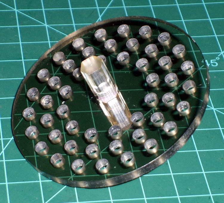
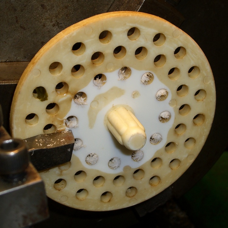
    Some years ago I machined a pair of smoke gray acrylic sink strainers (using LinuxCNC / EMC2 loops and trig functions) on the Sherline and wrote it up for my Digital Machinist column. They came out quite nicely:

    CNC Sink Strainer
    CNC Sink Strainer

    Then I did a 3D printed version on the Thing-O-Matic:

    Strainer plate fill
    Strainer plate fill

    Which produced a note about small features and another Digital Machinist column, of course.

    Subtractive machining is definitely the right hammer for some jobs…

  • UDEV Rules for M2’s HAL Devices

    Rather than have a bunch of separate rule files for each USB HID device I’ll be using with LinuxCNC on the M2, here they are in one lump:

    cat /etc/udev/rules.d/hal-input.rules
    # Rules to configure input device permissions for hal_input
    
    ATTRS{product}=="Nostromo SpeedPad2",GROUP="plugdev",MODE="0660"
    ATTRS{product}=="Arduino Leonardo",GROUP="plugdev",MODE="0660"
    ATTRS{product}=="Logitech Dual Action",GROUP="plugdev",MODE="0660"
    

    The strings are case-sensitive and must match exactly. That post (among others) describes the whole dance required to get all the information.

    Remember to add yourself to the plugdev group, too.

  • Marlin Firmware: Stepper Interrupt Timing

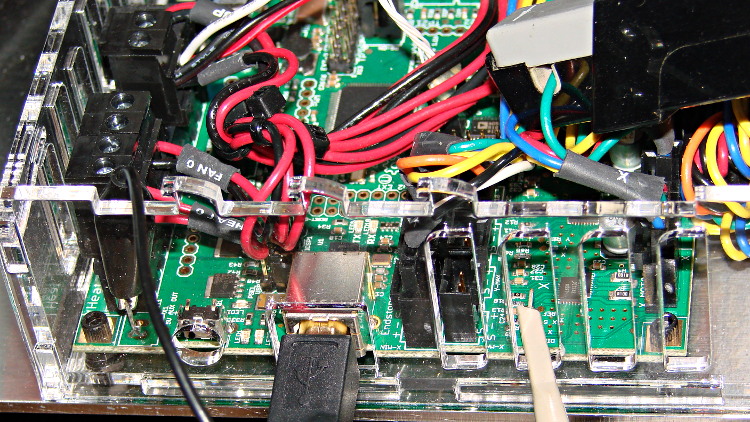
    Based on the discussion attached to the post on Z axis numbers, I wanted to take a look at the points where Marlin switches from one step per interrupt to two, then to four, just to see what the timing looks like. The RAMBo board has neatly labeled test points, to which I tack-soldered a pin for the scope probe poked through one of the ventilation slots, and an unused power connector on the left edge of the PCB that provided a ground point (admittedly, much too far away for good RF grounding, but it suffices for CMOS logic signals). The Tek Hall-effect current probe leaning in from the top right captures the current in one of the X axis windings:

    X axis Step and Current probes
    X axis Step and Current probes

    I’ve reset the Marlin constants based on first principles, per the notes on distance, speed, and acceleration, so they’re not representative of the as-shipped M2 firmware. Recapping the XY settings:

    • Distance: 88.89 step/mm
    • Speed: 450 mm/s = 27000 mm/min
    • Acceleration: 5000 mm/s2, with the overall limit at 10 m/s2

    The maximum interrupt frequency is about 10 kHz and the handler can issue zero, one, two, or four steps per axis per interrupt as required by the speed along each axis, up to a maximum of step rate of 40 kHz. There are complexities involved which I do not profess to understand.

    The maximum 10 kHz step rate for one-step-per-interrupt motion corresponds to a speed of:

    112.5 mm/s = (10000 step/s) / (88.89 step/mm)

    The maximum 40 kHz step rate produces, naturally enough, four times that speed:

    450 mm/s = (40000 step/s) / (88.89 step/mm)

    Assuming constant acceleration, the distance required to reach a given speed from a standing start or to decelerate from that speed to a complete stop is:
    x = v2 / (2 * a)

    The time required to reach that speed is:
    t = v/a

    Accelerating at 5000 mm/s2:

    • 112.5 mm/s = 6700 mm/min → 1.27 mm, 22.5 ms
    • 150 mm/s = 9000 mm/min → 2.25 mm, 30 ms
    • 450 mm/s = 27000 mm/min → 20.3 mm and 90 ms

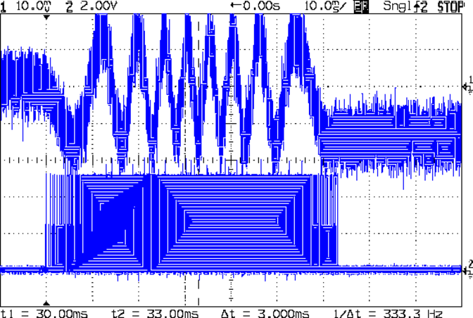
    An overview of a complete 6 mm move at 150 mm/s shows the acceleration and deceleration at each end, with a constant-speed section in the middle:

    X Axis 150 mm-s 6 mm - overview
    X Axis 150 mm-s 6 mm – overview

    The bizarre patterns in the traces come from hp2xx‘s desperate attempts to discern the meaning of the scope’s HPGL graphic data where the trace forms a solid block of color; take it as given that there’s no information in the pattern. I described the trace conversion process there.

    The upper trace shows the X axis motor winding current at a scale of 500 mA/div, with far more hash than one would expect. The RAMBo drivers evidently produce much more current noise than the brick drivers I intend to use.

    The lower trace is the X axis step signal produced by the Arduino microcontroller. You can barely make out the individual step signals at each end, but there’s not enough horizontal resolution to show them when the motor moves at a reasonable pace.

    In round numbers, the acceleration and deceleration should require about 30 ms each. The overall move takes 63 ms, so the constant-speed section in the middle must be about 3 ms long. That’s probably not right…

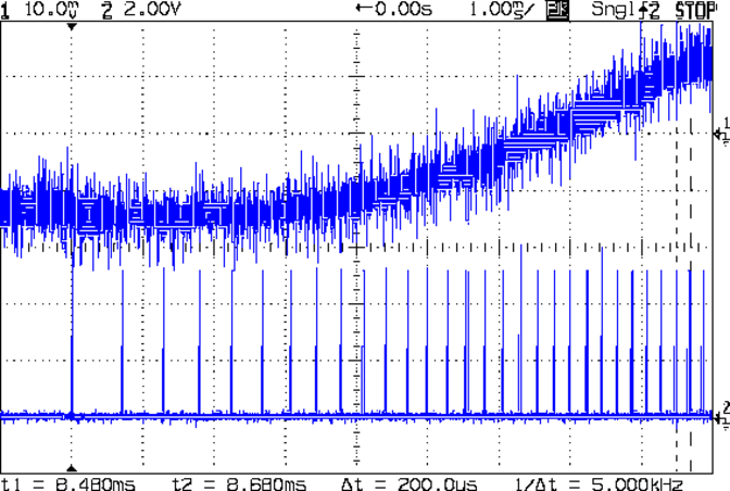
    Here’s a closer look at the step pulses as the motion starts from zero on the way to 150 mm/s:

    X Axis 150 mm-s 6 mm - 1 ms-div 0 ms dly
    X Axis 150 mm-s 6 mm – 1 ms-div 0 ms dly

    Over on the right, the 5 kHz step rate after 8.5 ms suggests a speed of 56 mm/s and counting 28 pulses says it moved 0.32 mm. Plugging those numbers into the equations:

    • a = v/t = 6600 mm/s2
    • a = (2 * x)/t2 = 8900 mm/s2

    It’s not clear (to me, anyway) whether:

    • The firmware accelerates faster than the alleged 5000 mm/s2 limit
    • It’s accelerating near the overall limit of 10000 mm/s2
    • The acceleration isn’t constant: starts high, then declines
    • The measurement accuracy doesn’t support any conclusions
    • I understand what’s happening

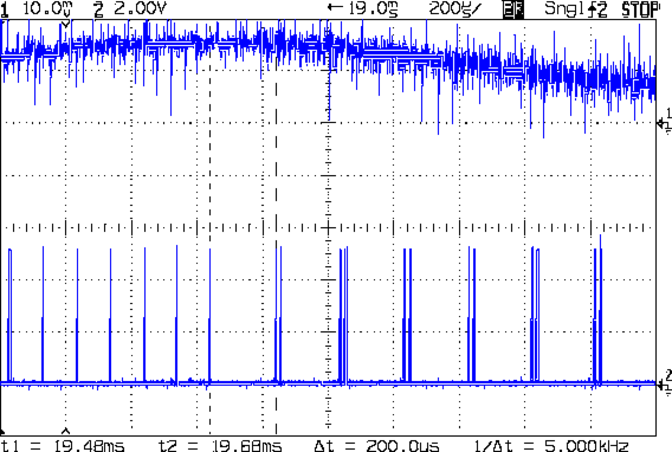
    In order to see the double- and quad-step outputs, here’s a 50 mm move at 450 mm/s, with a 19 ms delay to the point where the interrupt handler transitions from single-step to double-step output:

    X Axis 450 mm-s 50 mm - 200 us-div 19 ms dly
    X Axis 450 mm-s 50 mm – 200 us-div 19 ms dly

    The interrupt frequency drops from just under 10 kHz to a bit under 5 kHz, with the doubled pulses about 16 μs apart. At the transition, the axis speed is 112.5 mm/s, pretty much as predicted.

    If that’s the case, the overall acceleration to the transition works out to:

    5800 mm/s2 = (113 mm/s) / (19.5 ms)

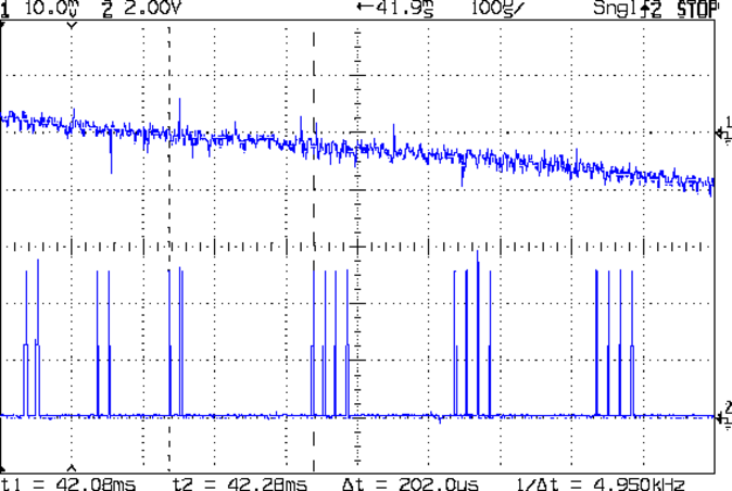
    Delaying the traces to 41.9 ms after the motion starts shows the double-to-quad step transition:

    X Axis 450 mm-s 50 mm - 100 us-div 41.9 ms dly
    X Axis 450 mm-s 50 mm – 100 us-div 41.9 ms dly

    Once again, the pulse frequency drops from 10 kHz down to 5 kHz. The speed is now 225 mm/s, half the maximum possible speed, which also makes sense: at top speed, the pulses will be essentially continuous at 40 kHz.

    The average acceleration from the start of the motion:

    5300 mm/s2 = (225 mm/s) / (42.1 ms)

    That implies the initial acceleration starts higher than the limit, but it evens out on the way to the commanded speed.

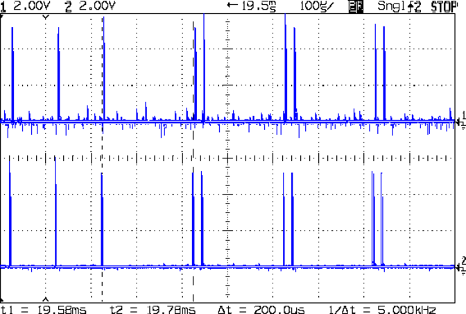
    Those scope shots come from moving only the X axis. Moving both the X and Y axes, with Trace 1 now showing the Y axis output, for 50 mm at 450 mm/s, produces similar results; the Y axis output lags the X axis by a few microseconds:

    XY 450 mm-s 50 mm - 100 us-div 19.5 ms dly
    XY 450 mm-s 50 mm – 100 us-div 19.5 ms dly

    Once again, that’s at the single- to double-step transition at 19+ ms. The overall timing doesn’t depend on how many axes are moving, as long as they can accelerate at the same pace; otherwise, the firmware must adjust the accelerations to make both axes track the intended path.

    None of this is too surprising.

    For a motor running at a constant speed just beyond the single-to-double step transition at 112.5 mm/s or the double-to-quad transition at 225 mm/s, the rotor motion should have a 5 kHz perturbation around its nominal position: it coasts for nearly the entire period, then a pair of steps kicks it toward the proper position. At those transitions, the rotor turns at:

    3.2 rev/s = (10000 step/s) / (3200 step/rev)
    6.4 rev/s = (20000 step/s) / (3200 step/rev)

    The perturbation should look like a 5 kHz oscillation (not exactly sinusoidal, maybe triangular?) superimposed on the nominal position, which is changing more-or-less parabolically as a function of time. I expect that the overall inertia damps it out pretty well, but I’d like to attach a rotary encoder to the motor shaft (or a linear encoder to the axis) to show the actual outcome, but I don’t have the machinery for that.

    In any event, LinuxCNC’s step outputs should behave better, which is why I’m doing this whole thing in the first place…

  • Arduino Leonardo + TC4 Thermocouple Shield + TC4 Server

    Because I want to measure several fairly high temperatures in and around the extruder with the LinuxCNC controller for the M2, I need a multi-channel thermocouple input. LinuxCNC’s hal_input interface module exposes the values produced by USB HID peripherals as HAL pins, which seems to be a nice way to add devices. A bit of searching revealed the TC4 Arduino Shield four-channel thermocouple + four-channel thermistor + assorted I/O board produced by the homeroasters.org folks as part of their DIY coffee roast controller.

    The gotcha: ordinary Arduino boards cannot (without extraordinary effort) become USB HID peripherals, as their USB interface works only as a serial data device. The solution: the new-ish Arduino Leonardo has an on-chip USB interface that can act as a USB HID peripheral as well as the usual serial device.

    Dan Newman, of Sailfish firmware fame, conjured up an a Arduino program (which, IMO, is far more complex than a mere sketch) that provides both a human-readable terminal interface and a LinuxCNC HAL-compatible USB HID interface using the Leonardo’s USB capabilities; the TC4Server project repository is on my GitHub account to keep it close to all the other stuff that should appear over the course of this project. His firmware builds on the libraries for the homeroaster’s tc4-shield Google Code project, but is intended for use with LinuxCNC, rather than as part of an Arduino controller.

    It’s worth noting that the Leonardo has a mere 32 kB of program storage, so the extensive help documentation built into the program helped prevent feature creep.

    Although I’m not yet using LinuxCNC with the M2, I can use TC4-Server’s serial terminal interface to read four channels of thermocouple data to help figure out what’s going on with the M2’s extruder thermistor. The TC4 shield has screw terminals for the thermocouples, but I also added a Proto ScrewShield board for thermistor resistors and easier connections:

    TC4 on ProtoScrewShield on Leonardo
    TC4 on ProtoScrewShield on Leonardo

    The TC4 Shield PCB layout assumes it’s being used with the original Arduino series of boards that bring the I2C (aka I2C, IIC, etc) SDA and SCL signals out on the A4 and A5 analog input pins, respectively. The newer Leonardo board brings SDA and SCL out in a separate header, so you must hotwire them across the board. The green and blue wires (stripped from a ribbon cable) accomplish that purpose: they’re plugged into the new Leonardo header through bent male header pins and clamped into the ScrewShield terminals. This assumes the Leonardo’s A4 and A5 pins remain as inputs, which is true for Dan’s firmware. If you actually need those pins for analog inputs, then you must remove the header pins that interconnect the boards and hotwire directly to the TC4 headers.

    The TC4 shield includes an on-board temperature sensor that serves as the thermocouple cold-junction compensation reference. In my simple tests, the board has about 1 °C of self-heating, so I also use it to report the ambient temperature.

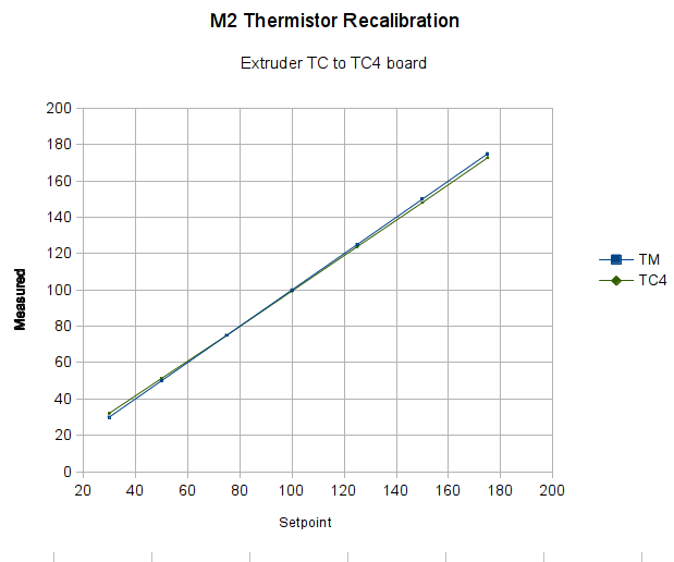
    With all that in hand, I connected the thermocouple epoxied to the M2’s nozzle to the TC4 and re-ran the previous test with the modified thermistor table:

    Rescaled extruder - thermocouple in TC4 board
    Rescaled extruder – thermocouple in TC4 board

    The TC4 shield produces the same result as the Fluke meter with the same thermocouple, so we know those results will be consistent.

    The modified thermistor table produces results that overlay thermocouple data. The questions come down to the accuracy of the thermocouple and whether bending the thermistor table actually represents an inherent property of the thermistor or just compensates for another problem.

    Part of my motivation for using thermocouples, rather than thermistors, is that thermocouples avoid the whole dance of matching a given thermistor with a set of properties. Given the uncertain provenance of most thermistors, I have no reason to believe any of them match their alleged datasheets…

  • M2 vs. Marlin: Step/mm Calculations

    After Dan Newman nudged me a bit in the comments to the Z axis calculations, I walked through the constants in Marlin’s Configuration.h file to see if they were all consistent. The earlier values sufficed to get going, but a bit of pondering suggested some tweaks.

    The motor microstepping mode determines the number of (micro)steps per motor (single)step:

    #define MICROSTEP16
    

    That single constant implies all motors must run in the same microstepping mode. Typical stepper motors have 200 full step/rev = 1.8°/step, so 1/16 microstepping means 3200 step/rev.

    However, each motor can have a different “gear” ratio that converts from motor rotation to linear distance, so you must measure or calculate the actual values.

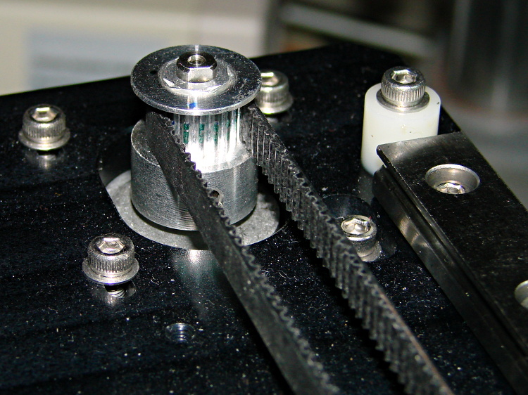
    For the X and Y axes, the motor pulleys have 18 teeth and the belt pitch is 2 mm/tooth, so one motor revolution drives the belt:

    36 mm = 18 teeth * 2 mm/tooth
    M2 - X axis motor pulley
    M2 – X axis motor pulley

    Each revolution requires 3200 steps, so the X and Y stages move at:

    88.888 step/mm = 3200 step / 36 mm

    Makergear uses 88.88 step/mm, rather than the rounded 88.89, but the difference across 250 mm amounts to 2.5 steps, so it doesn’t matter.

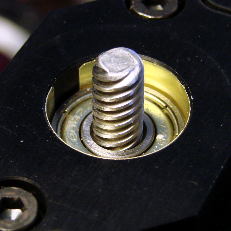
    For the Z axis, the four-start leadscrew moves the stage 8 mm, so:

    400 step/mm = 3200 step / 8 mm
    M2 Z axis bearing - shimstock bushing
    M2 Z axis bearing – shimstock bushing

    The situation with the extruder drive isn’t quite so clear, because the actual filament movement depends on the effective diameter of the drive pulley’s teeth engaging the filament. Mechanically, the extruder motor runs a 5:1 gearbox, so each drive pulley rotation requires 16000 (micro)steps.

    The filament drive pulley has 22 teeth and a 12.0 mm OD = 37.7 mm circumference:

    424.4 step/mm = 16000 step / 37.7 mm
    M2 - Filament Drive Gear
    M2 – Filament Drive Gear

    That’s measured at the tooth tip. If you think of the filament as being a belt, then you’d expect it to move precisely that distance… except that the teeth dig into the filament, so the effective diameter comes out a bit smaller and the step/mm value a bit higher.

    Makergear’s default 471.5 step/mm is, indeed, larger, but the ratio of the two values seems both oddly familiar and eerily exact:

    0.900 = 424.4 / 471.5

    The “packing density” Fudge Factor (yclept extrusion multiplier by slic3r) that accounts for the difference between the drive gear OD and the actual filament motion runs around 0.9, with passionate arguments justifying more specific values. It looks like Makergear baked that number into the firmware, so the nominal slic3r extrusion multiplier should be pretty close to 1.0.

    After a few quick measurements while getting the printer running, I settled on extrusion multiplier = 0.9, so the actual step/mm value in effect for the extruder works out to:

    424.4 = (471.5 step/mm) * 0.9

    Now, that would seem to imply that the filament skates along the top of teeth, but that’s not the case:

    M2 extruder - filament embossing
    M2 extruder – filament embossing

    So, for whatever reason, the effective diameter of the drive pulley matches its actual OD. That will surely vary with a number of imponderables, including the setting for the clamp screw holding the bearing against the filament and drive pulley.

    Being that type of guy, I favor baking the actual drive pulley OD into the firmware (because I can actually measure that value), then using the extrusion multiplier to account for the difference. I’ve heard cogent arguments to the contrary, but, for my purposes, the proper value for the extruder should 424.4 step/mm, with a corresponding extrusion multiplier change to 1.00 in slic3r’s configuration.

    I wouldn’t be surprised in the least to discover:

    • I’m multiplying where I should be dividing (or the other way around)
    • There’s a squaring / rooting operation hidden somewhere in there (area vs length)
    • Another obvious blunder has tripped me up

    Selah.

  • Logitech Dual Action Gamepads: Mac vs. PC

    Turns out that there’s no difference between the Mac and PC versions of the Logitech Dual Action Gamepad:

    Logitech Dual Action Gamepads - Mac vs PC
    Logitech Dual Action Gamepads – Mac vs PC

    I picked up a Mac version cheap from the usual eBay seller and discovered that LinuxCNC / HAL was perfectly happy. That wasn’t too surprising; they have the same model and part numbers. Most likely, the only difference was the CD and maybe the Quick Start Guide that I didn’t get in the opened retail box…

    So now I have either a hot backup for the Joggy Thing or one for a different box.

    Most likely, it was cheap because nobody wants a blue-and-black peripheral next to their shiny white Mac…