The Smell of Molten Projects in the Morning

Ed Nisley's Blog: Shop notes, electronics, firmware, machinery, 3D printing, laser cuttery, and curiosities. Contents: 100% human thinking, 0% AI slop.

Tag: CNC

Making parts with mathematics

  • Ubuntu 10.04LTS vs Foxconn D510 NIC: FAIL

    For some unknown reason, one of the very rare updates to the Ubuntu 10.04 LTS infrastructure (for LinuxCNC 2.5.3 on my Foxconn D510 box, driving the Sherline mill) stopped supporting the system board’s built-in NIC: networking stopped working. The only symptom was that the NIC didn’t respond and all the usual tricks were unproductive.

    After some fruitless searching, I took the easy way out:

    NIC added to Foxconn D510 PC
    NIC added to Foxconn D510 PC

    That’s the backside of an ancient NIC using the classic Tulip driver. It used to have a full-size bracket, which I chopped off, bent, and filed to suit, much as with that one in the D525.

    Fired it up, the kernel automagically picked the proper driver, and networking Just Worked again.

    There. Fixed that…

  • Thing-o-Matic 286 Conversion

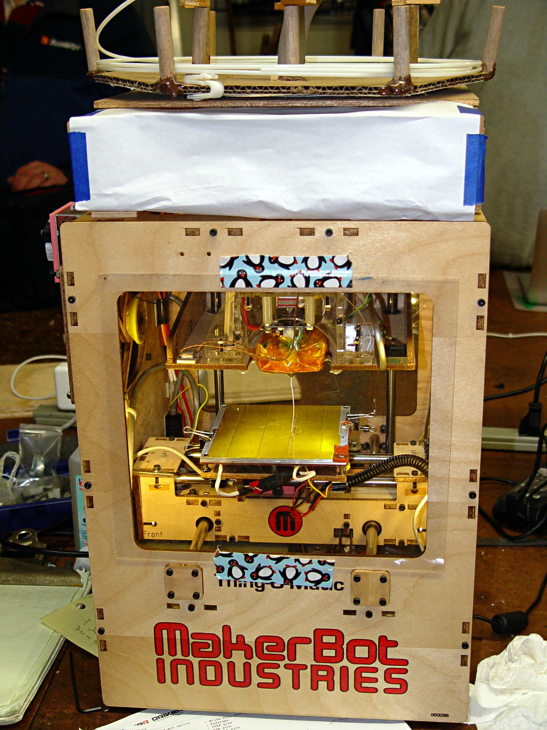
    A few months ago I fired the Thing-O-Matic, only to have it wake up dead. Not exactly dead, but spitting out checksum errors on simple G-Code files sent from Pronterface, which used to work just fine. Trying a bit of this-and-that to no avail, I proposed to The Mighty Thor that I could loan the carcass to Squidwrench, reanimate it with a less bizarre set of hardware and firmware than the much-hacked Makerbot menagerie under the hood, and use it as an exemplar in my 3D Printing classes.

    Fortunately, that particular Thing-O-Matic has the most well-documented hardware evah…

    Matt suggested an Azteeg X3 controller, because it has thermocouple inputs that match the existing sensor, Thor ordered one, and I tinkered up a first-pass version of Marlin that could read the inputs and twiddle the motors. The firmware is on Github, not that you’ll need it for anything you’re doing; more on that later.

    Here’s the Official Doc for the microstepping jumpers hidden under the driver boards:

    Azteeg X3 - microstep jumpers
    Azteeg X3 – microstep jumpers

    That’s XYZE = 16 16 8 4, respectively, with a spare slot (and spare driver, not installed) for the second extruder it’ll never have.

    A first pass at setting the motor currents

    The extruder’s Type K thermocouple connects to the TC1 port on the shield, exactly reversed from the way you see the test thermocouple there: the red lead is to the left, the yellow lead is to the right. If you get it backwards, the indicated temperature goes down when you touch the bead. The printer’s thermocouple has some backstory.

    The 10 kΩ thermistor bead connects to the BED port on the main board and isn’t polarized. The Heated Build Platform has a bit of backstory, too.

    The gutted TOM286 carcass with the MBI hardware off to the side:

    TOM286 - gutted electronics bay
    TOM286 – gutted electronics bay

    After a few sessions, it looked pretty cheerful again:

    TOM286 - reborn at Squidwrench
    TOM286 – reborn at Squidwrench

    The penguin duct tape adds a festive flair, don’t you agree?

    This is what you see when looking down through the acrylic baseplate:

    Azteeg X3 - inside TOM286
    Azteeg X3 – inside TOM286

    The blurry silver rectangle off to the left is an aluminum channel glommed to bottom of the acrylic baseplate with silicone snot to eliminate a nasty mechanical resonance.

    The thermal cutout circuitry isn’t wired in yet; the ATX power supply has its -Power-On pin hotwired to the adjacent ground pin for now. The X3 gets its power directly from the +12 V supply, so there doesn’t seem to be any way to power the X3 from the +5 V Standby ouput, deliver +12 V to the motors, and switch the supply through the X3’s ATX output pin.

    The heaters work fine, the motors turn properly, and the extruder feeds molten plastic; all the motor calibrations seem to be pretty close. The first test object was a total botch, of course, but the printer’s parts seem to work OK again.

    Next step: calibration!

  • Water Cooled Stepper Motors: Flow Calculation

    A discussion on the Makergear Google Group about a heated enclosure prompted me to run the numbers for cooling stepper motors with water, rather than fans and finned heatsinks.

    The general idea comes from my measurements of the air-cooled heatsink stuck to a stepper’s end cap. The metal-to-metal conductivity works surprisingly well and reduces the case temperature to slightly over ambient with decent airflow through the heatsink; epoxying a cold plate to the end cap should work just as well. A NEMA 17 stepper case is 42.3 mm square, so a standard 40 mm square CPU cooling plate will fit almost exactly.

    The question then becomes: how much water flow do you need to keep the motors cool?

    Some numbers:

    • Water’s heat capacity is 4.2 J/g·K
    • 1 J = 1 W·s, 1 W = 1 J/s
    • NEMA 17 motors dissipate about 5 W (13 W if you’re abusing them)
    • We’ll cool all four motors in parallel, for a total of 20 W
    • Allow a 5 K = 5 °C temperature rise in each cold plate

    Rub them all together:

    (20 J/s) / (5 K * (4.2 J/g·K)) = 0.95 g/s

    For water, 1 g = 1 cc, so the total flow is 1 cc/s = 3600 cc/h = 3.6 liter/h, which, here in the US, works out to a scant 1 gallon/hour. It’s tough getting a pump that small and cheap flowmeters run around 0.5 liter/m…

    If you don’t want a pump. put an aquarium up on a (sturdy) shelf and drain it through the cold plates. A cubic foot of water, all eight gallons and sixty-some-odd pounds of it, will last 8 hours, which should be enough for most printing projects.

    If you want reliability, drain the coolers into a sump with a float switch (high = on), put another float switch (high = off) on the aquarium, and have the pump top up the aquarium. If the pump fails, your steppers stay cool for the next 8 hours. Heating the water about 5 °C during 8 hours won’t require active cooling.

    Now, managing the hoses leading to the X axis stepper may be challenging, but a cable drag chain would control the rest of the wiring, too.

  • Browning Hi-Power Magazine Capacity Reduction Block: Steel Version

    The Shapeways stainless steel process produces nice results:

    Browning HP Mag Blocks - stainless and plastic - side
    Browning HP Mag Blocks – stainless and plastic – side

    It’s actually bronze-infused stainless steel powder, so it’s not exactly solid steel. The parts spend a day rattling around in a vibratory polisher that slightly rounds off their edges and smooths the surface, but (as with all 3D printed objects) you must learn to love the results; it’s certainly more photogenic than the black plastic version from my M2.

    The bottom view shows the hole I added to reduce the metallic volume; they charge a bit under $0.01/mm3, which encourages airy design:

    Browning HP Mag Blocks - stainless and plastic - bottom
    Browning HP Mag Blocks – stainless and plastic – bottom

    A cross-section view of the solid model shows the interior structure:

    Browning Hi-Power Magazine Block - steel - solid model - section
    Browning Hi-Power Magazine Block – steel – solid model – section

    The vent pipes are somewhat larger than in the plastic version and, obviously, I didn’t include the yellow support structures in the model I sent to Shapeways.

    Their specs give a minimum wall thickness of 3.0 mm, which I’m definitely pushing on some of the internal features. The pipes came out perfectly, as nearly as I can tell, although some polishing media did get wedged in the smaller hole. Air passes freely across the top, which is the important part.

    Although the specs list a ±2 mm (!) tolerance, a comment in a Shapeways forum said that applies to larger objects, with 0.2 mm being typical for smaller objects. The steel and plastic parts match within 0.2 mm of the nominal model dimensions, so that lower tolerance seems about right; I have no idea how consistent it is.

    Another comment recommended carbide tools for secondary operations and that’s definitely true; I wrecked a perfectly good HSS tap trying to thread the central hole. Fortunately, I made the block slightly smaller outside and slightly larger inside, specifically to avoid having a deep thread; I intend to ram a standard M3x0.5 SHCS into that hole and epoxy it in place without worrying about thread damage.

    A trial fit shows it captures the spring tab just like the plastic version did:

    Browning Hi-Power magazine - steel block trial fit
    Browning Hi-Power magazine – steel block trial fit

    I must contact my legislators again, as I’m pretty sure they’re not going to contact me.

    The OpenSCAD source code:

    // Browning Hi-Power Magazine Plug
    // Ed Nisley KE4ZNU December 2013
    
    Layout = "Show";			// Show Whole Split
    							//  Show = section view for demo, not for building
    							//  Whole = upright for steel or plastic
    							//  Split = laid flat for plastic show-n-tell assembly
    
    AlignPins = (Layout == "Split");					// pins only for plastic show-n-tell
    
    Support = true && (Layout != "Split");				// no support for split, optional otherwise
    
    //- Extrusion parameters must match reality!
    //  Print with 2 shells and 3 solid layers
    
    ThreadThick = 0.15;
    ThreadWidth = 0.40;
    
    HoleWindage = 0.2;
    
    Protrusion = 0.1;			// make holes end cleanly
    
    //----------------------
    // Dimensions
    
    Angle = 12.5;				// from vertical
    
    SpringID = 10.3;			// magazine spring curvature (measure with drill shank)
    SpringRadius = SpringID / 2;
    
    Length = 23.0;				// front-to-back perpendicular to magazine shaft
    Height = 18.0;				// bottom-to-top, parallel to magazine shaft
    							//  18 = 10 round max capacity
    
    RectLength = Length - SpringID;	// block length between end radii
    
    HornBaseOD = 8.0;			// fits between follower pegs to prevent shortening
    HornTipOD = 5.0;
    HornAddTip = (HornTipOD/2)*tan(Angle);
    HornAddBase = (HornBaseOD/2)*tan(Angle);
    HornAddLength = HornAddTip + HornAddBase + 2*Protrusion;
    HornLength = 12.0;			// should recompute ODs, but *eh*
    
    ScrewOD = 3.0 - 0.25;		// screw hole dia - minimal thread engagement
    ScrewLength = 13.0;
    ScrewOffset = -1.5;			//   ... from centerline
    							//  OEM = 0.0
    							//  generic A = -1.5
    
    NutOD = 5.6;				// hex nut dia across flats
    NutThick = 2.4;				//  ... generous allowance for nut
    NutTrapLength = 1.5*NutThick;		// allow for epoxy buildup
    NutOffset = 6.0;			//  ... base height from floor
    
    TrimHeight = 2.5;			// vertical clearance for spring clip on base plate
    							//   OEM = 2.5
    							//   generic A = 2.5
    
    TrimOffset = -9.5 + ScrewOffset;	// ... horizontal from centerline
    							//	 OEM = 0.0
    							//   generic A = 1.5
    
    SupportLength = 4.0;		// length of support struts under Trim
    SupportWidth = SpringID;	// ... width
    
    VentDia = 2.5;				// air vent from back of screw recess
    VentOffset = ScrewOffset - 6.0;
    
    RecessDia = 5.0;			// recess to reduce weight
    RecessLength = 0.66*Length;	//  ... internal length
    RecessOffset = 8.5;	//  ... offset from centerline
    
    PinOD = 1.72;				// alignment pins
    PinLength = 6.0;
    PinInset = 0.6*SpringRadius;	// from outside edges
    echo(str("Alignment pin length: ",PinLength));
    
    NumSides = 8*4;				// default cylinder sides
    
    Offset = 5.0/2;				// from centerline for build layout
    
    //----------------------
    // Useful routines
    
    function Delta(a,l) = l*tan(a);				// incremental length due to angle
    
    // Locating pin hole with glue recess
    //  Default length is two pin diameters on each side of the split
    
    module LocatingPin(Dia=PinOD,Len=0.0) {
    
    	PinLen = (Len != 0.0) ? Len : (4*Dia);
    
    	translate([0,0,-ThreadThick])
    		PolyCyl((Dia + 2*ThreadWidth),2*ThreadThick,4);
    
    	translate([0,0,-2*ThreadThick])
    		PolyCyl((Dia + 1*ThreadWidth),4*ThreadThick,4);
    
    	translate([0,0,-(Len/2 + ThreadThick)])
    		PolyCyl(Dia,(Len + 2*ThreadThick),4);
    
    }
    
    module PolyCyl(Dia,Height,ForceSides=0) {			// based on nophead's polyholes
    
      Sides = (ForceSides != 0) ? ForceSides : (ceil(Dia) + 2);
    
      FixDia = Dia / cos(180/Sides);
    
      cylinder(r=(FixDia + HoleWindage)/2,
               h=Height,
    	   $fn=Sides);
    }
    
    module ShowPegGrid(Space = 10.0,Size = 1.0) {
    
      Range = floor(50 / Space);
    
    	for (x=[-Range:Range])
    	  for (y=[-Range:Range])
    		translate([x*Space,y*Space,Size/2])
    		  %cube(Size,center=true);
    
    }
    
    //----------------------
    // The magazine block
    
    module Block(SectionSelect = 0) {
    
    CropHeight = Height*cos(Angle);				// block height perpendicular to base
    echo(str("Perpendicular height: ",CropHeight));
    
    	difference() {
    		union() {
    			intersection() {
    				rotate([Angle,0,0])
    					hull() {
    						for (i=[-1,1])
    							translate([0,i*RectLength/2,-((Length/2)*sin(Angle) + Protrusion)])						cylinder(r=SpringRadius,
    										h=(Height + 2*(Length/2)*sin(Angle) + 2*Protrusion),
    										$fn=NumSides);
    					}
    				translate([0,0,CropHeight/2])
    					cube([2*SpringID,3*Length,CropHeight],center=true);
    			}
    			translate([0,-Height*sin(Angle),Height*cos(Angle)])
    				resize([SpringID,0,0])
    					intersection() {
    						rotate([Angle,0,0])
    							translate([0,0,-(HornAddBase + Protrusion)])
    								cylinder(r1=HornBaseOD/2,
    										r2=HornTipOD/2,
    										h=(HornLength + HornAddLength + Protrusion),
    										$fn=NumSides);
    					cube([2*SpringID,Length,2*(HornLength*cos(Angle) + Protrusion)],center=true);
    				}
    		}
    
    		translate([0,ScrewOffset,-Protrusion])		// screw
    			rotate(180/6)
    				PolyCyl(ScrewOD,(ScrewLength + Protrusion),6);
    
    		translate([0,ScrewOffset,NutOffset])		// nut trap in center
    			rotate(180/6)
    				PolyCyl(NutOD,NutTrapLength,6);
    
    		translate([0,ScrewOffset,-Protrusion])		// nut clearance at base
    			rotate(180/6)
    				PolyCyl(NutOD,(1.1*NutThick + Protrusion),6);
    
    		translate([SpringID/2,TrimOffset,-Protrusion])
    			rotate(180)
    				cube([SpringID,Length,(TrimHeight + Protrusion)],center=false);
    
    		if (AlignPins)								// alignment pins
    			for (i=[-1,1])
    				rotate([Angle,0,0])
    				translate([0,
    							(i*((Length/2)*cos(Angle) - PinInset)),
    							(CropHeight/2 - i*2*PinInset)])
    					rotate([0,90,0]) rotate(45 - Angle)
    						LocatingPin(PinOD,PinLength);
    
    		translate([0,(ScrewOffset + 1.25*NutOD),ScrewLength])	// air vent
    			rotate([90,0,0]) rotate(180/8)
    				PolyCyl(VentDia,3*NutOD,8);
    		translate([0,VentOffset,-(VentDia/2)*tan(Angle)])
    			rotate([Angle,0,0]) rotate(180/8)
    				PolyCyl(VentDia,(RecessLength + (VentDia/2)*tan(Angle)),8);
    
    		translate([0,(RecessOffset + ScrewOffset),0])			// weight reduction recess
    			rotate([Angle,0,0]) rotate(180/8)
    				translate([0,0,-((RecessDia/2)*tan(Angle))])
    				PolyCyl(RecessDia,(RecessLength + (RecessDia/2)*tan(Angle)),8);
    
    		if (SectionSelect == 1)
    			translate([0*SpringID,-2*Length,-Protrusion])
    				cube([2*SpringID,4*Length,(Height + HornLength + 2*Protrusion)],center=false);
    		else if (SectionSelect == -1)
    			translate([-2*SpringID,-2*Length,-Protrusion])
    				cube([2*SpringID,4*Length,(Height + HornLength + 2*Protrusion)],center=false);
    	}
    
    SupportBars = floor((SupportWidth/2) / (4*ThreadWidth));
    
    	if (Support) {									// add support structures
    		for (i = [-SupportBars:SupportBars])
    			translate([i*4*ThreadWidth,
    					   (TrimOffset - SupportLength/2 - ThreadWidth),
    					   (TrimHeight - ThreadThick)/2])
    				color("Yellow")
    				cube([(2*ThreadWidth),SupportLength,(TrimHeight - ThreadThick)],center=true);
    
    		translate([0,(TrimOffset - SupportLength - ThreadWidth),(TrimHeight - ThreadThick)/2])
    			color("Yellow")
    			cube([SupportWidth,(2*ThreadWidth),(TrimHeight - ThreadThick)],center=true);
    
    		translate([0,ScrewOffset,0])
    			for (j=[0:5]) {
    			rotate(30 + 360*j/6)
    				translate([(NutOD/2 - ThreadWidth)/2,0,(1.1*NutThick - ThreadThick)/2])
    					color("Yellow")
    					cube([(NutOD/2 - ThreadWidth),
    						  (2*ThreadWidth),
    						  (1.1*NutThick - ThreadThick)],
    						  center=true);
            }
    	}
    
    }
    
    //-------------------
    // Build it...
    
    ShowPegGrid();
    
    if (Layout == "Show")
    	Block(1);
    
    if (Layout == "Whole")
    	Block(0);
    
    if (Layout ==  "Split") {
    	translate([(Offset + Length/2),Height/2,0])
    		rotate(90) rotate([0,-90,-Angle])
    			Block(-1);
    	translate([-(Offset + Length/2),Height/2,0])
    		rotate(-90) rotate([0,90,Angle])
    			Block(1);
    }
    
  • Planetary Gear Bearing: Now With Knurling!

    OK, I couldn’t resist. Tweaking a few lines of code wrapped a knurl around emmitt’s Gear Bearing for enhanced griptivity:

    Knurled vs original Planetary Gear Bearing
    Knurled vs original Planetary Gear Bearing

    That image has desaturated red to suppress the camera’s red burnout. It looks better in the realm of pure math:

    Planetary Gear Bearing - Kurled - solid model
    Planetary Gear Bearing – Kurled – solid model

    Reducing the tolerance parameter to 0.4 produced a surprisingly rigid, yet freely turning, bearing that required no cleanup: it popped off the plate ready to roll!

    The heavy lifting in the OpenSCAD source code remains emmitt’s work. I replaced the outer cylinder with a knurl and simplified his monogram to stand out better amid the diamonds. This is the affected section:

    ... snippage ...
    translate([0,0,T/2]){
    	difference(){
    //		cylinder(r=D/2,h=T,center=true,$fn=100);
    		render(convexity=10)
    		translate([0,0,-T/2])
    			knurl(k_cyl_hg=T,
    			k_cyl_od=D,
    			knurl_wd=5.0,
    			knurl_hg=5.0,
    			knurl_dp=0.5,
    			e_smooth=5.0/2);
    		herringbone(nr,pitch,P,DR,-tol,helix_angle,T+0.2);
    //		difference(){
    			translate([0,-(D/2+4.5),0])rotate([90,0,0])monogram(h=10);
    //			cylinder(r=D/2-0.25,h=T+2,center=true,$fn=100);
    //		}
    	}
    	rotate([0,0,(np+1)*180/ns+phi*(ns+np)*2/ns])
    	difference(){
    		mirror([0,1,0])
    			herringbone(ns,pitch,P,DR,tol,helix_angle,T);
    		cylinder(r=w/sqrt(3),h=T+1,center=true,$fn=6);
    	}
    	for(i=[1:m])rotate([0,0,i*360/m+phi])translate([pitchD/2*(ns+np)/nr,0,0])
    		rotate([0,0,i*ns/m*360/np-phi*(ns+np)/np-phi])
    			render(convexity=10)
    			herringbone(np,pitch,P,DR,tol,helix_angle,T);
    }
    

    I also added a few render(convexity=n) operations to improve the preview, but that’s just cosmetic.

  • Gauge Block Set Oiling

    Ray’s Rule of Precision:

    Measure with a micrometer. Mark with chalk. Cut with an axe.

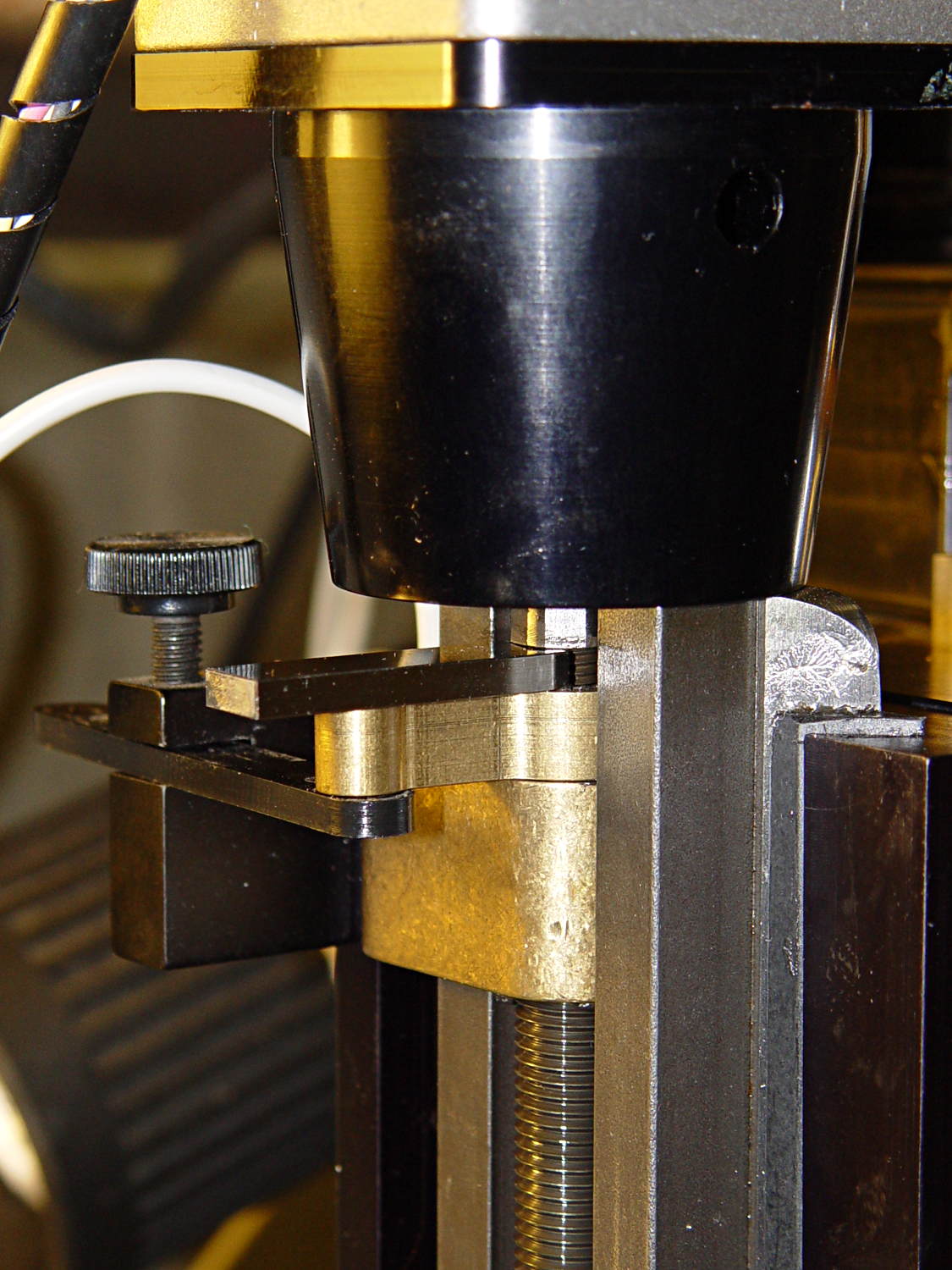
    While pondering the problem of having the Sherline’s Z-axis anti-backlash nut unscrew at the top of its travel, I excavated the gauge block set and measured the gap between it and the bearing preload nut:

    Sherline Z-axis leadscrew nut - gauge block
    Sherline Z-axis leadscrew nut – gauge block

    Turns out that it’s 0.1340 inches, determined by bracketing the sliver above that 0.1300 block with feeler gauges. I don’t believe that last zero, either, as the Basement Shop was about 10 °F below the block’s 68 °F calibration temperature.  [grin]

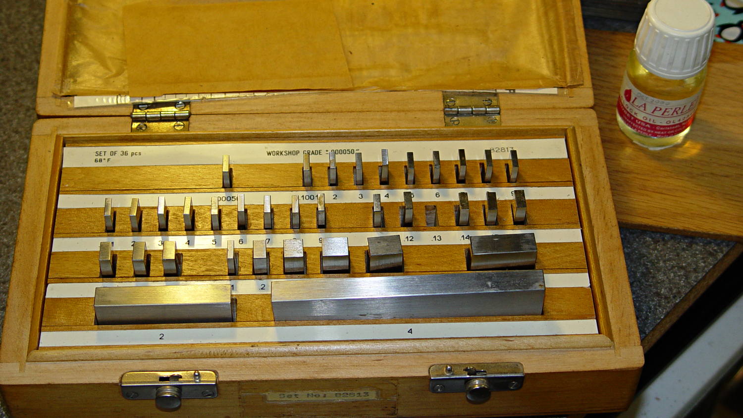
    The actual size of that gap makes absolutely no difference whatsoever, but fooling around with the gauge blocks gave me an excuse to renew my acquaintance with them and, en passant, massage some oil over their long-neglected bodies:

    Gauge block set
    Gauge block set

    I used La Perle Clock Oil, which isn’t Official Gauge Block Oil, but doesn’t go bad on the shelf. Verily, this bottle may be the last of its kind, as it’s no longer available from any of the usual sources; it appears I bought it back in 2000.

    The blocks are in good shape, probably because they don’t often see the light. FWIW, I have experimentally determined that my body oil doesn’t etch fingerprints into steel.

    The block set, which is similar to a current box o’ blocks from Enco, claims “Workshop Grade”, but the ±0.00050 inch = 1.27 μm tolerance shown in the top row of the labels is much worse than even grade B’s sub-micron tolerance. That newer box claims “Economy” accuracy with the same spec, so I suppose somebody kvetched about mis-using the terms.

    Ah, well, they’re far better than any measurements I’ve needed in a while and entirely suitable for verifying my other instruments.

  • Sherline CNC Mill Z-axis Overrun Prevention Block

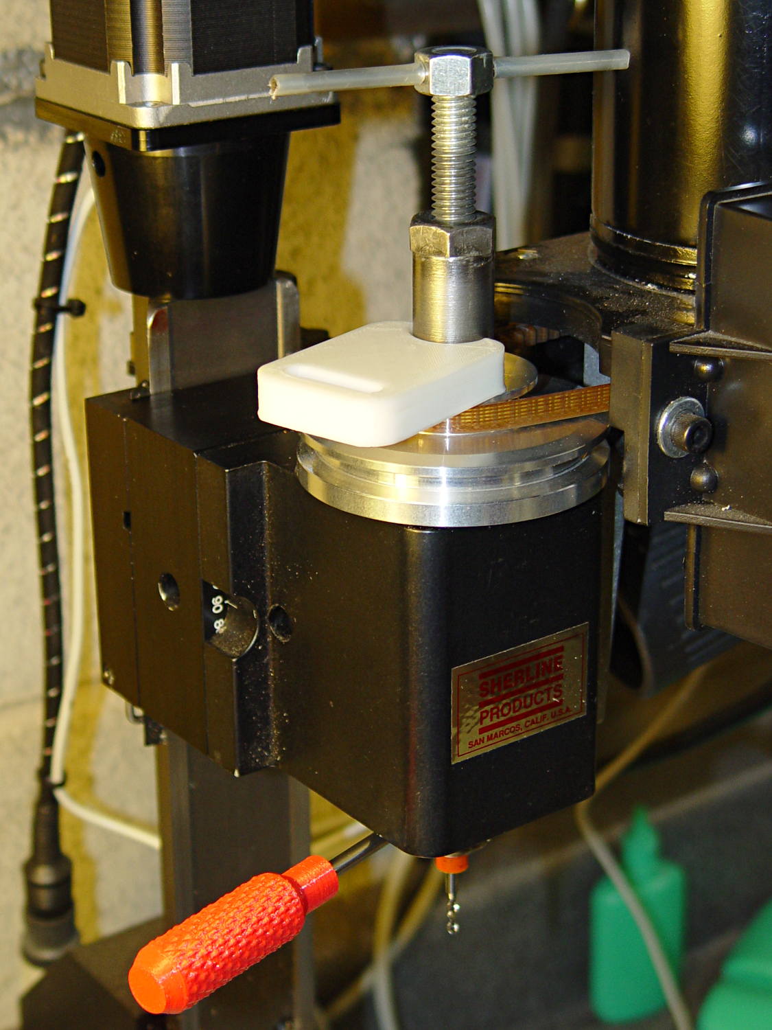
    The alert reader will already have noticed the absence of the Z-axis home switch in this picture from yesterday’s post:

    Sherline CNC mill - tommy bar and collet pusher
    Sherline CNC mill – tommy bar and collet pusher

    Turns out that I managed to crunch it, exactly as I expected: I’d added a block to the Z-axis stage that poked the home switch just slightly before the anti-backlash nut unscrewed from the top of the leadscrew, but the stage could continue moving another few millimeters.

    You can see the gap just above the brass anti-backlash nut:

    Sherline Z-axis leadscrew nut - top end
    Sherline Z-axis leadscrew nut – top end

    At that point, the nut has barely a single micro-smidgen of thread engaged; that last 0.1340 inch of travel (yeah, I measured it) isn’t usable.

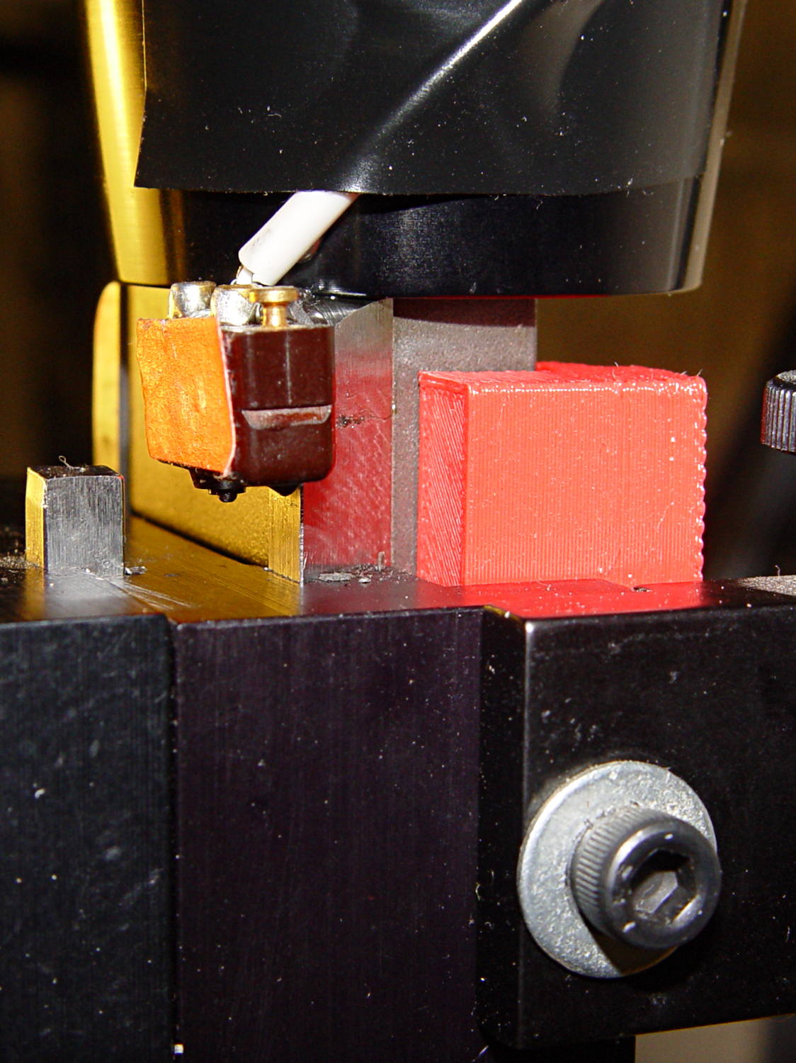
    Rather than put a collar around the end of the leadscrew, I opted for a brute-force block atop the Z-axis saddle nut that will slam into the bottom of the stepper motor mount just before the anti-backlash nut disengages:

    Sherline Z-axis Overrun Block - rear view
    Sherline Z-axis Overrun Block – rear view

    A strip of tapeless sticky (double-sided tape, minus the tape) holds the block in place on the saddle nut. It’s not subject to any particular stress: as long as it doesn’t fall off, it’s all good.

    I ran the stage upward until it stalled, then epoxied a new switch (with the old fluorescent tape) in place. This shows the result after backing the stage down a few millimeters:

    Sherline Z-axis Overrun Block - side view
    Sherline Z-axis Overrun Block – side view

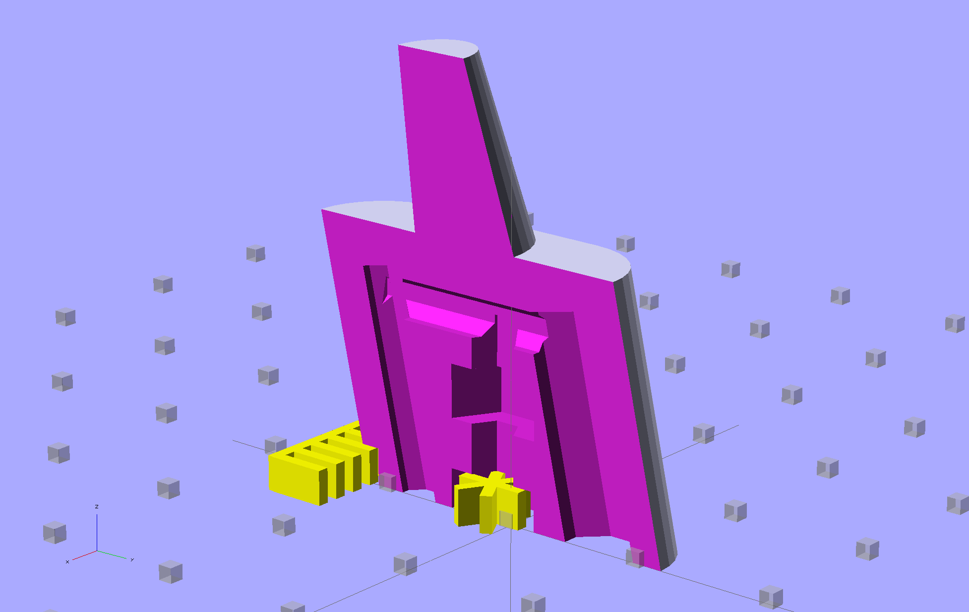
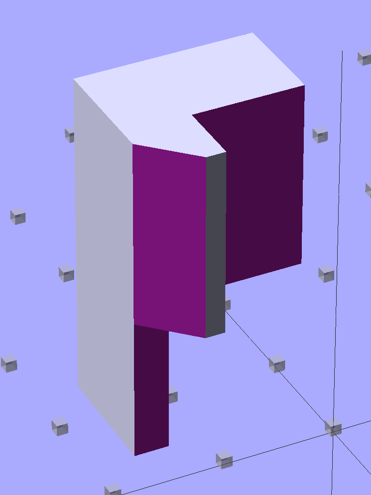
    The solid model shows off the bevel that provides a bit more room for anti-backlash nut adjustment, not that I ever adjust it that much:

    Sherline Z-Axis Overrun Prevention Block - solid model
    Sherline Z-Axis Overrun Prevention Block – solid model

    Obviously, it doesn’t print in that position, but it’s easier to design it in the natural orientation and flip it around for printing.

    The OpenSCAD source code:

    // Sherline Z-axis Overrun Prevention Block
    // Ed Nisley KE4ZNU December 2013
    
    Layout = "Show";			// Show Build
    
    //- Extrusion parameters must match reality!
    //  Print with 2 shells and 3 solid layers
    
    ThreadThick = 0.25;
    ThreadWidth = 0.40;
    
    HoleWindage = 0.2;
    
    Protrusion = 0.1;			// make holes end cleanly
    
    //----------------------
    // Dimensions
    
    BlockZ = 30.0;				// overall height
    ZLimit = 17.0;				// Z travel limit
    
    TongueX = 9.0;				// beside Z axis dovetail
    TongueY = 10.0;
    
    StubX = 6.0;				// behind Z axis pillar
    StubY = 3.0;
    
    BlockX = TongueX + StubX;	// overall X
    
    TabY = 3.0;					// behind brass bracket
    TabX = BlockX - sqrt(2)*TabY;
    TabZ = BlockZ - ZLimit;
    
    BlockY = TongueY + StubY + TabY;	// overall Y
    
    //----------------------
    // Useful routines
    
    module ShowPegGrid(Space = 10.0,Size = 1.0) {
    
      Range = floor(50 / Space);
    
    	for (x=[-Range:Range])
    	  for (y=[-Range:Range])
    		translate([x*Space,y*Space,Size/2])
    		  %cube(Size,center=true);
    
    }
    
    //- The Block
    
    module Block() {
    
    	difference() {
    		cube([BlockX,BlockY,BlockZ]);
    
    		translate([-Protrusion,-Protrusion,-Protrusion])	// remove column
    			cube([(StubX + Protrusion),(TongueY + Protrusion),2*BlockZ]);
    
    		translate([-BlockX/2,-Protrusion,-Protrusion])		// form tab
    			cube([2*BlockX,(TongueY + StubY),(TabZ + Protrusion)]);
    
    		translate([0,BlockY,(BlockZ/2 - 0*Protrusion)])
    			rotate(45)
    				cube([3*StubY,2*StubY,(BlockZ + 2*Protrusion)],center=true);
    
    		translate([0,0,-Protrusion])
    			cube([sqrt(2)*TabY,2*BlockY,(TabZ + Protrusion)]);
    	}
    }
    
    //-------------------
    // Build it...
    
    ShowPegGrid();
    
    if (Layout == "Show")
    	Block();
    
    if (Layout == "Build")
    	translate([-BlockZ/2,-BlockY/2,BlockX])
    	rotate([0,90,0])
    		Block();