The alert reader will already have noticed the absence of the Z-axis home switch in this picture from yesterday’s post:
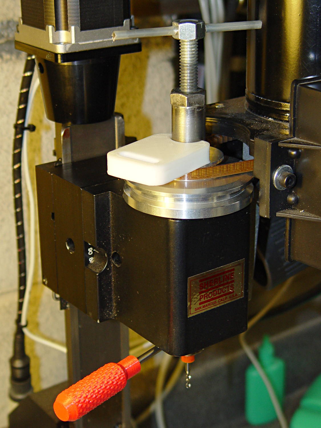
Turns out that I managed to crunch it, exactly as I expected: I’d added a block to the Z-axis stage that poked the home switch just slightly before the anti-backlash nut unscrewed from the top of the leadscrew, but the stage could continue moving another few millimeters.
You can see the gap just above the brass anti-backlash nut:

At that point, the nut has barely a single micro-smidgen of thread engaged; that last 0.1340 inch of travel (yeah, I measured it) isn’t usable.
Rather than put a collar around the end of the leadscrew, I opted for a brute-force block atop the Z-axis saddle nut that will slam into the bottom of the stepper motor mount just before the anti-backlash nut disengages:

A strip of tapeless sticky (double-sided tape, minus the tape) holds the block in place on the saddle nut. It’s not subject to any particular stress: as long as it doesn’t fall off, it’s all good.
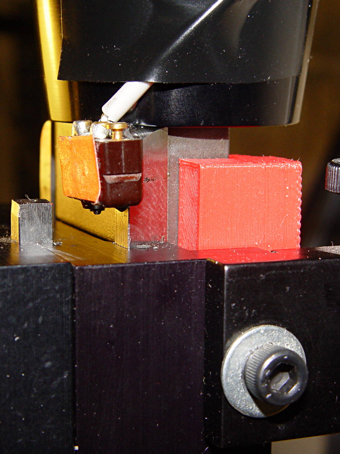
I ran the stage upward until it stalled, then epoxied a new switch (with the old fluorescent tape) in place. This shows the result after backing the stage down a few millimeters:
The solid model shows off the bevel that provides a bit more room for anti-backlash nut adjustment, not that I ever adjust it that much:
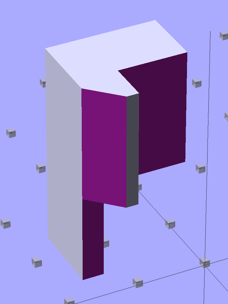
Obviously, it doesn’t print in that position, but it’s easier to design it in the natural orientation and flip it around for printing.
The OpenSCAD source code:
// Sherline Z-axis Overrun Prevention Block
// Ed Nisley KE4ZNU December 2013

Layout = "Show";			// Show Build

//- Extrusion parameters must match reality!
//  Print with 2 shells and 3 solid layers

ThreadThick = 0.25;
ThreadWidth = 0.40;

HoleWindage = 0.2;

Protrusion = 0.1;			// make holes end cleanly

//----------------------
// Dimensions

BlockZ = 30.0;				// overall height
ZLimit = 17.0;				// Z travel limit

TongueX = 9.0;				// beside Z axis dovetail
TongueY = 10.0;

StubX = 6.0;				// behind Z axis pillar
StubY = 3.0;

BlockX = TongueX + StubX;	// overall X

TabY = 3.0;					// behind brass bracket
TabX = BlockX - sqrt(2)*TabY;
TabZ = BlockZ - ZLimit;

BlockY = TongueY + StubY + TabY;	// overall Y

//----------------------
// Useful routines

module ShowPegGrid(Space = 10.0,Size = 1.0) {

  Range = floor(50 / Space);

	for (x=[-Range:Range])
	  for (y=[-Range:Range])
		translate([x*Space,y*Space,Size/2])
		  %cube(Size,center=true);

}

//- The Block

module Block() {

	difference() {
		cube([BlockX,BlockY,BlockZ]);

		translate([-Protrusion,-Protrusion,-Protrusion])	// remove column
			cube([(StubX + Protrusion),(TongueY + Protrusion),2*BlockZ]);

		translate([-BlockX/2,-Protrusion,-Protrusion])		// form tab
			cube([2*BlockX,(TongueY + StubY),(TabZ + Protrusion)]);

		translate([0,BlockY,(BlockZ/2 - 0*Protrusion)])
			rotate(45)
				cube([3*StubY,2*StubY,(BlockZ + 2*Protrusion)],center=true);

		translate([0,0,-Protrusion])
			cube([sqrt(2)*TabY,2*BlockY,(TabZ + Protrusion)]);
	}
}

//-------------------
// Build it...

ShowPegGrid();

if (Layout == "Show")
	Block();

if (Layout == "Build")
	translate([-BlockZ/2,-BlockY/2,BlockX])
	rotate([0,90,0])
		Block();
