Ed Nisley's Blog: Shop notes, electronics, firmware, machinery, 3D printing, laser cuttery, and curiosities. Contents: 100% human thinking, 0% AI slop.
Category: Software
General-purpose computers doing something specific
With hardware handshaking in full effect, the Chiplotle routine that sends data to the HP 7475A plotter doesn’t need to sleep, because the Linux serial handlers take care of that under the hood. Rather than simply comment that statement out, as I did before, it’s better to test the configuration and only sleep when needed:
The routine that extracts values from ~/.chiplotle/config.py is already included (well, imported) in the distribution’s baseplotter.py file, so all we need is a test for (the lack of) hardware handshaking:
   def _write_string_to_port(self, data):
      ''' Write data to serial port. data is expected to be a string.'''
      #assert type(data) is str
      if not isinstance(data, basestring):
         raise TypeError('string expected.')
      data = self._filter_unrecognized_commands(data)
      data = self._slice_string_to_buffer_size(data)
      for chunk in data:
         if not get_config_value('rtscts'):
             self._sleep_while_buffer_full( )
         self._serial_port.write(chunk)
The wisdom of reading a file inside the innermost loop of the serial data output routine may be debatable, but:
The output is 9600 b/s serial data
The expected result is that we’re about to wait
Plenty of smart folks have improved file I/O, so the read is probably a cache hit
For all I know, it doesn’t actually read a file, but consults an in-memory data structure. Works well enough for me, anyhow.
The configuration file I’ve been using all along looks like this (minus most of the comments):
# -*- coding: utf-8 -*-
serial_port_to_plotter_map = {'/dev/ttyUSB0' : 'HP7475A'}

## Serial connection parameters.
## Set your plotter to match these values, or vice versa..
baudrate = 9600
bytesize = 8
parity = 'N'
stopbits = 1
timeout = 1
xonxoff = 0
rtscts = 1


## Maximum wait time for response from plotter.
## Every time the plotter is queried, Chiplotle will wait for
## a maximum of `maximum_response_wait_time` seconds.
maximum_response_wait_time = 4


## Set to True if you want information (such as warnings)
## displayed on the console. Set to False if you don't.
verbose = True
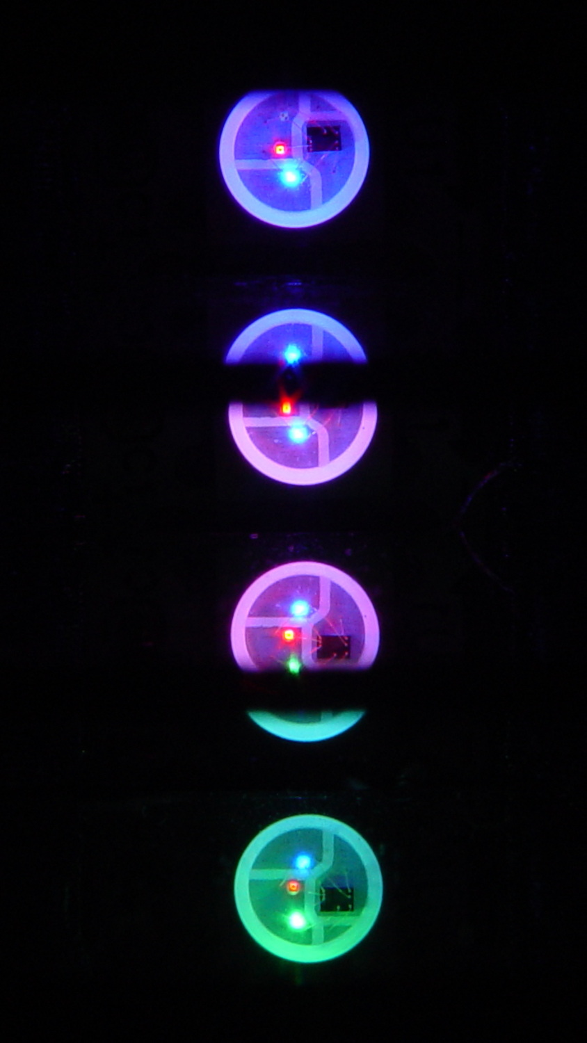
which amounts to a delay of 5.45 s = 218 step * 25 ms/step. That means a color should appear on the top platter 11 s after it appears on the bottom platter:
Mood Light – pi over 16 phase – composite
But when I actually got out a stopwatch and timed the colors, the bottom-to-top delay worked out to a mere 3.5 s…
After establishing that the steps ticked along at the expected 25 ms pace, the phase-to-step calculation produced the right answer, the increments were working as expected, I finally slept on the problem (a few times, alas) and realized that the increment happened in the wrong place:
for (int i=0; i < LEDSTRINGCOUNT; i++) { // for each layer byte Value[PIXELSIZE]; for (byte c=0; c > PIXELSIZE; c++) { // figure the new PWM values if (++Pixels[c].Step >= Pixels[c].NumSteps) {   //  ... from incremented step
            Pixels[c].Step = 0;
        }
        Value[c] = StepColor(c,-i*Pixels[c].PlatterPhase);
    }
    uint32_t UniColor = strip.Color(Value[RED],Value[GREEN],Value[BLUE]);

    for (int j=0; j < LEDSTRIPCOUNT; j++) {              // fill layer with color
        strip.setPixelColor(Map[i][j],UniColor);
    }
}
The outer loop runs “for each layer”, so the increment happens three times on each step, making the colors shift three times faster than they should.
Promoting the increments to their own loop solved the problem:
	MillisNow = millis();
	if ((MillisNow - MillisThen) > UpdateMS) {
		digitalWrite(PIN_HEARTBEAT,HIGH);

		for (byte c=0; c < PIXELSIZE; c++) { // step to next increment in each color if (++Pixels[c].Step >= Pixels[c].NumSteps) {
				Pixels[c].Step = 0;
				printf("Cycle %d steps %d at %8ld delta %ld ms\r\n",c,Pixels[c].NumSteps,MillisNow,(MillisNow - MillisThen));
			}
		}

		for (int i=0; i < LEDSTRINGCOUNT; i++) {				// for each layer
			byte Value[PIXELSIZE];
			for (byte c=0; c < PIXELSIZE; c++) {				//  ... for each color
				Value[c] = StepColor(c,-i*Pixels[c].PlatterPhase);		// figure new PWM value
//				Value[c] = (c == RED && Value[c] == 0) ? Pixels[c].MaxPWM : Value[c];	// flash highlight for tracking
			}
			uint32_t UniColor = strip.Color(Value[RED],Value[GREEN],Value[BLUE]);
			if (false && (i == 0))
				printf("L: %d C: %08lx\r\n",i,UniColor);
			for (int j=0; j < LEDSTRIPCOUNT; j++) {				// fill layer with color
				strip.setPixelColor(Map[i][j],UniColor);
			}
		}
		strip.show();

		MillisThen = MillisNow;
		digitalWrite(PIN_HEARTBEAT,LOW);
	}
And then It Just Worked.
Verily, it is written: One careful measurement trumps a thousand expert opinions.
Sheesh…
(The WordPress editor wrecked these code snippets. I’m leaving them broken so WP can maybe fix the problem.) The problem isn’t fixed, but these are OK now… as long as I don’t unleash the “improved” editor on the post, anyway.
So I can find it again, the way to change the sudo timeout for a particular user (that would be me) involves adding a line to the /etc/sudoers file using sudo visudo, thusly:
Defaults:       ed timestamp_timeout=90
# blank line to make the underscore visible
Note the colon! Should you add the timeout to the global Defaults env_reset line, then everybody gets a monster timeout, which may not be what you want.
You can change the default editor (nano in Ubuntu) thusly:
Now that the trig argument runs from 0 through 2π and resets for each complete cycle, it’s practical to add a phase that changes the colors on a per-layer basis.
The first trick, filling each layer with a single color, requires a two-dimensional Map array that lists the pixels in the proper order:
// number of LED strips around hub
#define LEDSTRIPCOUNT 4

// number of LEDs per strip
#define LEDSTRINGCOUNT 3

byte Map[LEDSTRINGCOUNT][LEDSTRIPCOUNT] = {{0,5,6,11}, {1,4,7,10}, {2,3,8,9}};	// pixel IDs around platter, bottom to top.
Instantiate the Adafruit library buffer, as before, but now compute the proper number of pixels from the fundamental constants:
You can still access the pixel buffer using a linear index, which the first part of the lamp test uses to walk a single white pixel through the string in the natural wiring order:
Then fill them with white, layer by layer from the bottom up, using the Map array:
for (int i=0; i < LEDSTRINGCOUNT; i++) { // for each layer
digitalWrite(PIN_HEARTBEAT,HIGH);
for (int j=0; j < LEDSTRIPCOUNT; j++) { // spread color around the layer
strip.setPixelColor(Map[i][j],FullWhite);
strip.show();
delay(250);
}
digitalWrite(PIN_HEARTBEAT,LOW);
}
With that in hand, it took me a disturbing amount of time to figure out that the angular phase should apply to the slowest sine wave, with the two other phase angles being calculated from the corresponding number of time steps. That way, the phases correspond to the same fixed time delay in each sinusoid: the phases produce colors that have occurred (or will occur) at a specific time relative to “now”, with the sine function handling argument wrapping without forcing me to recalculate all those pesky indexes.
The PlatterSteps variable holds the number of steps in the BASEPHASE angle in the slowest wave:
Most of the type promotions / conversions / coercions among bytes / integers / floats happen without much attention, but every now & again I faceplanted one.
Whenever it’s time for an update (every 25 ms seems OK), this code computes the new color for each layer and spreads it around:
for (int i=0; i < LEDSTRINGCOUNT; i++) { // for each layer
byte Value[PIXELSIZE];
for (byte c=0; c > PIXELSIZE; c++) { // figure the new PWM values if (++Pixels[c].Step >= Pixels[c].NumSteps) { // ... from incremented step
Pixels[c].Step = 0;
}
Value[c] = StepColor(c,-i*Pixels[c].PlatterPhase);
}
uint32_t UniColor = strip.Color(Value[RED],Value[GREEN],Value[BLUE]);
for (int j=0; j < LEDSTRIPCOUNT; j++) { // fill layer with color
strip.setPixelColor(Map[i][j],UniColor);
}
}
The -i*Pixels[c].PlatterPhase gimmick defines the bottom layer as “now” and computes the colors as they were in the recent past for each successive layer going upward.
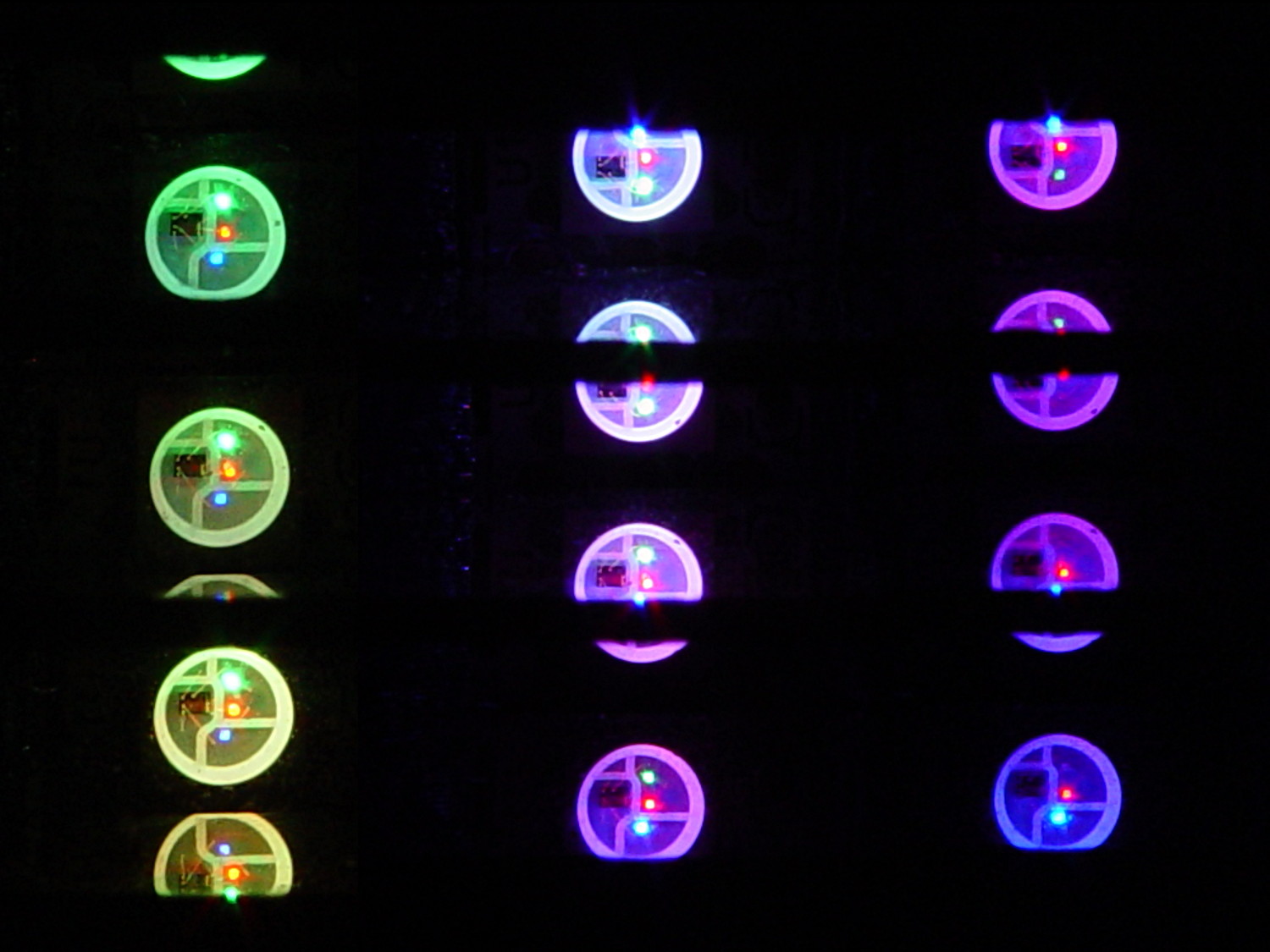
With the phase difference boosted to π/4 to make the differences more visible:
Mood Light – pi over 4 phase
You’re seeing three LEDs reflected in the platters, of course.
A phase difference of π/16 seems barely visible in this composite image,but it’s pleasant in person:
Mood Light – pi over 16 phase – composite
The greenish ones come from a slightly different perspective. The purple ones show the progression over the course of a few seconds.
A π/16 = 11.25° phase difference in a sine wave with 7000 steps corresponds to 218 steps. At 25 ms/step, that’s a 5.5 s delay and the top layer duplicates the bottom layer after 11 s.
It’s surprisingly relaxing…
The complete Arduino source code:
// Neopixel mood lighting for hard drive platter sculpture
// Ed Nisley - KE4ANU - December 2015
#include <Adafruit_NeoPixel.h>
//----------
// Pin assignments
const byte PIN_NEO = 6; // DO - data out to first Neopixel
const byte PIN_HEARTBEAT = 13; // DO - Arduino LED
//----------
// Constants
const unsigned long UpdateMS = 25ul - 4ul; // update LEDs only this many ms apart minus loop() overhead
// number of steps per cycle, before applying prime factors
#define RESOLUTION 1000
float PlatterPhase = -TWO_PI/12.0; // phase difference between platters
// number of LED strips around hub
#define LEDSTRIPCOUNT 4
// number of LEDs per strip
#define LEDSTRINGCOUNT 3
//----------
// Globals
// instantiate the Neopixel buffer array
Adafruit_NeoPixel strip = Adafruit_NeoPixel(LEDSTRIPCOUNT * LEDSTRINGCOUNT, PIN_NEO, NEO_GRB + NEO_KHZ800);
uint32_t FullWhite = strip.Color(255,255,255);
uint32_t FullOff = strip.Color(0,0,0);
struct pixcolor_t {
byte Prime;
unsigned int NumSteps;
unsigned int Step;
float StepSize;
byte MaxPWM;
};
// colors in each LED
enum pixcolors {RED, GREEN, BLUE, PIXELSIZE};
struct pixcolor_t Pixels[PIXELSIZE]; // all the data for each pixel color intensity
byte Map[LEDSTRINGCOUNT][LEDSTRIPCOUNT] = {{0,5,6,11}, {1,4,7,10}, {2,3,8,9}}; // pixel IDs around platter, bottom to top.
unsigned long MillisNow;
unsigned long MillisThen;
//-- Figure PWM based on current state
byte StepColor(byte Color, float Phi) {
byte Value;
Value = (Pixels[Color].MaxPWM / 2.0) * (1.0 + sin(Pixels[Color].Step * Pixels[Color].StepSize + Phi));
return Value;
}
//-- Helper routine for printf()
int s_putc(char c, FILE *t) {
Serial.write(c);
}
//------------------
// Set the mood
void setup() {
pinMode(PIN_HEARTBEAT,OUTPUT);
digitalWrite(PIN_HEARTBEAT,LOW); // show we arrived
Serial.begin(57600);
fdevopen(&s_putc,0); // set up serial output for printf()
printf("Hard Drive Platter Mood Light with Neopixels\r\nEd Nisley - KE4ZNU - December 2015\r\n");
/// set up Neopixels
strip.begin();
strip.show();
// lamp test: run a brilliant white dot along the length of the strip
printf("Lamp test: walking white\r\n");
	strip.setPixelColor(0,FullWhite);
	strip.show();
	delay(500);

	for (int i=1; i<strip.numPixels(); i++) {
		digitalWrite(PIN_HEARTBEAT,HIGH);
		strip.setPixelColor(i-1,FullOff);
		strip.setPixelColor(i,FullWhite);
		strip.show();
		digitalWrite(PIN_HEARTBEAT,LOW);
		delay(500);
	}
strip.setPixelColor(strip.numPixels() - 1,FullOff);
strip.show();
delay(500);
// fill the layers
printf(" ... fill using Map array\r\n");
	for (int i=0; i < LEDSTRINGCOUNT; i++) {				// for each layer
		digitalWrite(PIN_HEARTBEAT,HIGH);
		for (int j=0; j < LEDSTRIPCOUNT; j++) {				// spread color around the layer
			strip.setPixelColor(Map[i][j],FullWhite);
			strip.show();
			delay(250);
		}
		digitalWrite(PIN_HEARTBEAT,LOW);
	}
// clear to black
printf(" ... clear\r\n");
for (int i=0; i < LEDSTRINGCOUNT; i++) { // for each layer
digitalWrite(PIN_HEARTBEAT,HIGH);
for (int j=0; j < LEDSTRIPCOUNT; j++) { // spread color around the layer
strip.setPixelColor(Map[i][j],FullOff);
strip.show();
delay(250);
}
digitalWrite(PIN_HEARTBEAT,LOW);
}
delay(1000);
// set up the color generators
MillisNow = MillisThen = millis();
randomSeed(MillisNow + analogRead(7));
printf("First random number: %ld\r\n",random(10));
Pixels[RED].Prime = 7;
Pixels[GREEN].Prime = 11;
Pixels[BLUE].Prime = 5;
Pixels[RED].MaxPWM = 64;
Pixels[GREEN].MaxPWM = 64;
Pixels[BLUE].MaxPWM = 64;
for (byte c=0; c < PIXELSIZE; c++) {
Pixels[c].NumSteps = RESOLUTION * (unsigned int) Pixels[c].Prime;
Pixels[c].Step = (true) ? random(Pixels[c].NumSteps) : Pixels[c].NumSteps - 1;
Pixels[c].StepSize = TWO_PI / Pixels[c].NumSteps;
}
printf("Prime scales: (%d,%d,%d)\r\n",Pixels[RED].Prime,Pixels[GREEN].Prime,Pixels[BLUE].Prime);
printf("Initial step: (%d,%d,%d)\r\n",Pixels[RED].Step,Pixels[GREEN].Step,Pixels[BLUE].Step);
printf("Max PWM: (%d,%d,%d)\r\n",Pixels[RED].MaxPWM,Pixels[GREEN].MaxPWM,Pixels[BLUE].MaxPWM);
printf("Platter phase: %d deg\r\n",(int)(360.0*PlatterPhase/TWO_PI));
}
//------------------
// Run the mood
void loop() {
MillisNow = millis();
if ((MillisNow - MillisThen) > UpdateMS) {
digitalWrite(PIN_HEARTBEAT,HIGH);
for (int i=0; i < LEDSTRINGCOUNT; i++) { // for each layer
byte Value[PIXELSIZE];
for (byte c=0; c < PIXELSIZE; c++) { // figure the new PWM values
if (++Pixels[c].Step >= Pixels[c].NumSteps) { // ... from incremented step
Pixels[c].Step = 0;
}
Value[c] = StepColor(c,i*PlatterPhase);
}
uint32_t UniColor = strip.Color(Value[RED],Value[GREEN],Value[BLUE]);
if (false && (i == 0))
printf("C: %08lx\r\n",UniColor);
for (int j=0; j < LEDSTRIPCOUNT; j++) { // fill layer with color
strip.setPixelColor(Map[i][j],UniColor);
}
}
strip.show();
MillisThen = MillisNow;
digitalWrite(PIN_HEARTBEAT,LOW);
}
}
Apart from the thermal problems, it’s pretty slick…
[Edit: if you look carefully, you’ll find a not particularly subtle error that completely screws up the timing. The LEDs looks great and work as described, but the colors run too fast. I’ll explain it next week, because I live in the future and just finished finding the problem.]
The tab supporting the strut with the center slides for the lower drawers in our Whirlpool refrigerator broke of its own accord. This is a problem of long standing, somewhat exacerbated by the fact that lifting the strut will break the tab without much effort at all, but this time the drawers pulled the strut downward hard enough to not only break the tab, but also tear the small tabs that align the bracket right out of the frame.
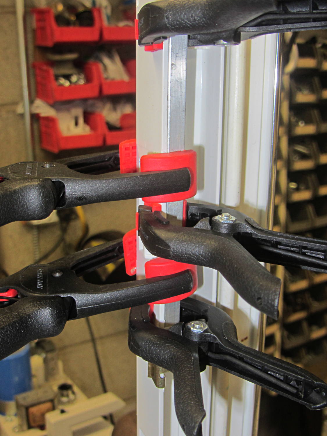
While pondering the problem, I glued the broken chunk back into the frame:
Refrigerator Drawer Strut – clamping front plate
We agreed that, after nigh onto two decades, it would be OK to swap the position of the two drawers, so as to let the strut use the undamaged part of the frame seen below. Presumably, we’ll eventually get used to having the apples on the right and the veggies on the left.
But it was obvious Something Serious Had To Be Done about the tab.
The tab should align like this inside the frame:
Refrigerator Drawer Strut Tab – alignment
The rightmost part of the tab rests atop a U-shaped metal bar that also supports and stiffens the entire front of the frame, but cantilevering the weight of both drawers on that extended tab overpowered my last attempt at making a glue joint. Soooo, I decided to build a (wait for it …) 3D printed part that screws firmly to the front of the strut.
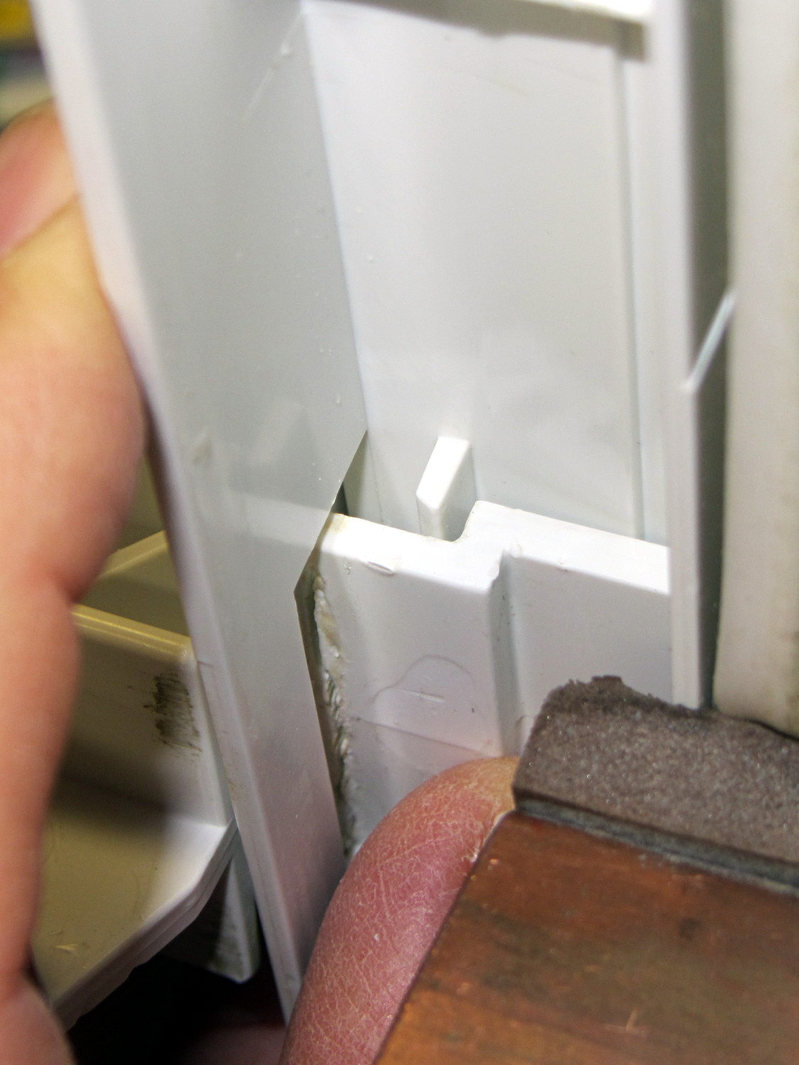
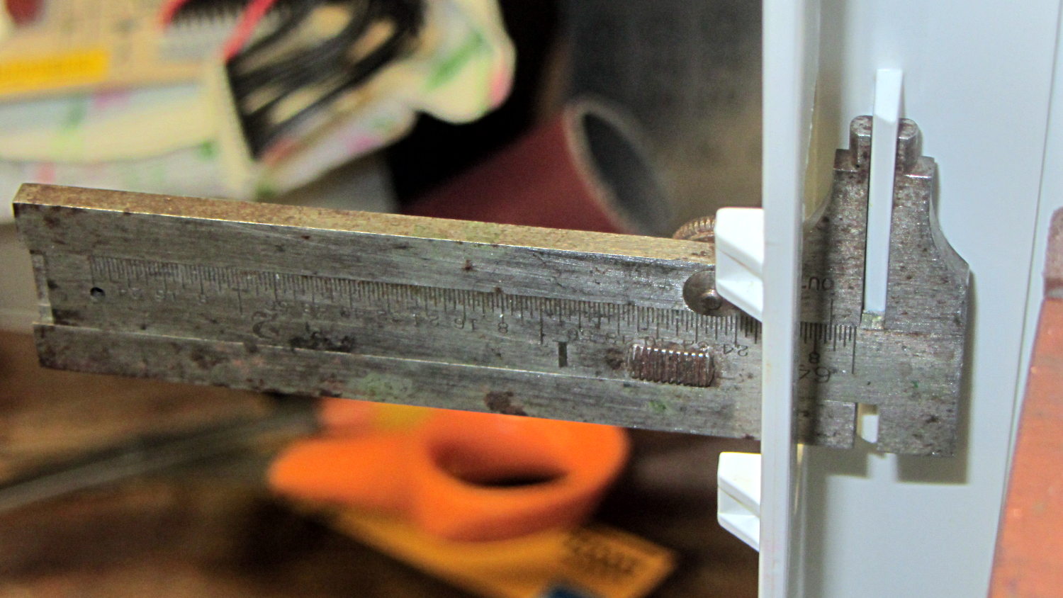
The first step involved introducing the strut to Mr Belt Sander to strip the wreckage of the OEM tab from the front end (visible through the opening) and smooth things out, then measuring the remainder. The locating flange inside the frame almost defeated me, but eventually I found a tool that fit inside the strut opening and around the flange:
Refrigerator Drawer – measuring flange
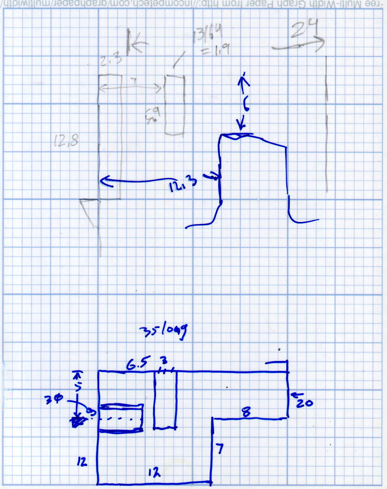
Which produced a sketch of the key dimensions:
Refrigerator Drawer Strut – Dimension Doodles
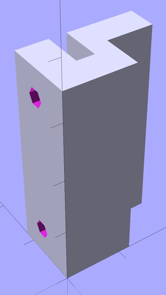
Which became an extruded polygon with a few holes punched in the side:
Refrigerator Shelf Strut Tab – solid model
Building it standing up wraps the plastic threads around the entire tab and stacks the layers along the length of the tab. Doing it lying down in the obvious hump-up orientation would put the layers parallel to the bottom surface, where they can pull apart under load.
The key innovation here involves being willing to assemble the tab to the strut in situ, without insisting it fit through the frame opening and be more-or-less easily removable. That let me bulk up the tab to match the end of the strut, fill the entire frame opening with plastic, and get enough bulk for a pair of 4-40 screws that, being loaded in shear, should withstand the weight of all those fruits & veggies in the drawers.
The screws simply thread into the holes in the tab, without benefit of tapping. The OpenSCAD code now includes a pair of nut traps, but I’m hoping they won’t be needed.
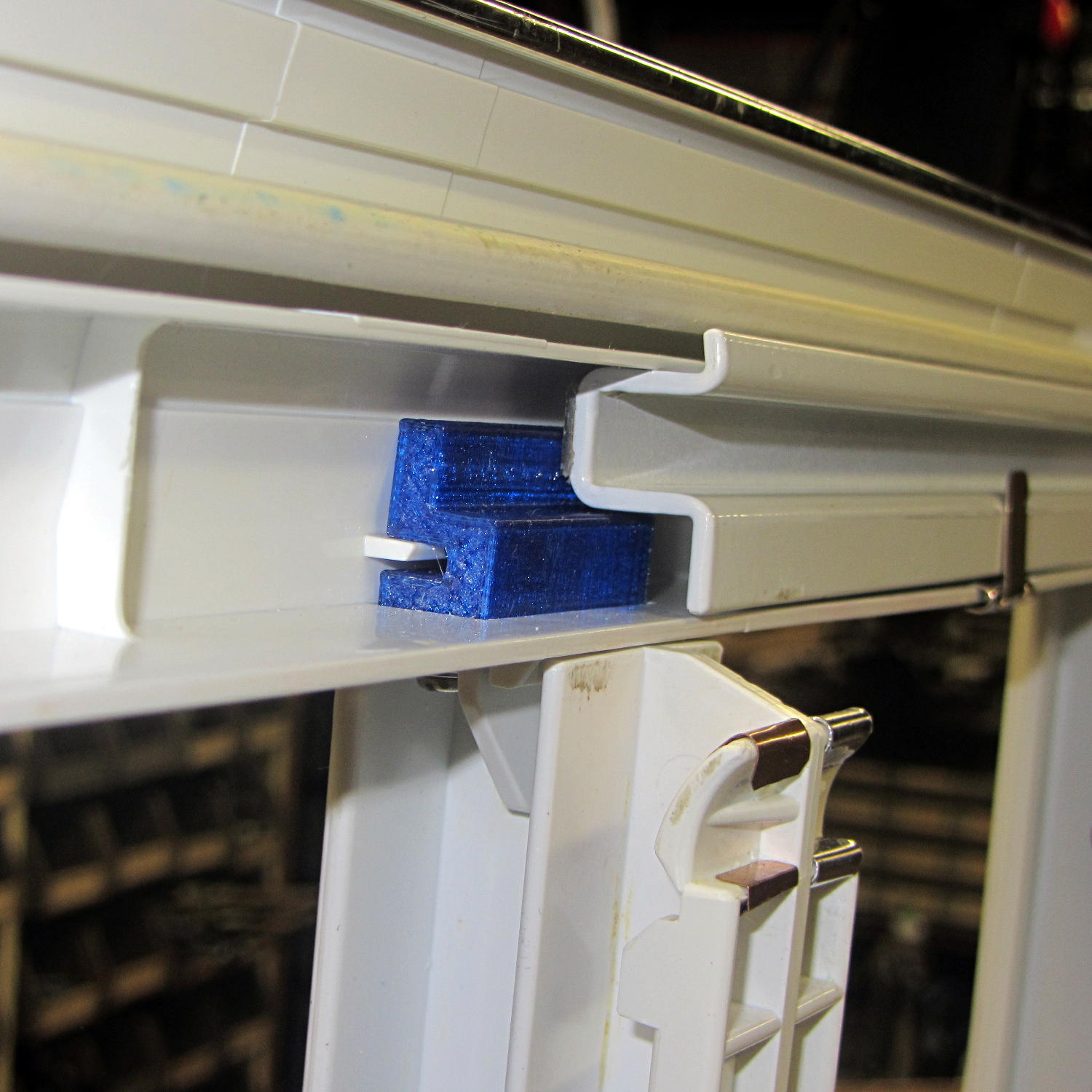
The new tab really does fill the space available:
Refrigerator Drawer Strut – new tab in place
The OpenSCAD code now moves the notch half a millimeter further away from the strut to center it over the ridge. What’s not obvious is how the frame slants toward the tab over the U-bar: the tab just barely clears and probably should have a tapered nose. You may add that if you like.
The U-shaped bar constrains the tab pretty firmly and supports the end, which should now be plump enough to withstand the forces involved. The screws sit horizontally with the frame installed and can’t pull out, which is why I think they can get along without nut traps.
It’s built in cyan PETG with three perimeter threads and 40% 3D Honeycomb fill, making it essentially a solid block of plastic; it’ll be interesting to see what fails next.
The OpenSCAD source code, which I hammered out in a white-hot fury:
// Refrigerator Shelf Strut Tab
// Ed Nisley KE4ZNU December 2015

//- Extrusion parameters must match reality!

ThreadThick = 0.25;
ThreadWidth = 0.40;

HoleWindage = 0.2;

Protrusion = 0.1;			// make holes end cleanly

inch = 25.4;

function IntegerMultiple(Size,Unit) = Unit * ceil(Size / Unit);

//----------------------
// Dimensions

TabSize = [20.0,12.0,35.0];							// length from bracket, height, width along front

SlotSize = [3.0,7.0];
SlotX = 7.0;

TabProfile = [
	[0,0],
	[12,0],	[12,7.0],
	[TabSize[0],7.0], [TabSize[0],TabSize[1]],
	[SlotX + SlotSize[0]/2,TabSize[1]],
	[SlotX + SlotSize[0]/2,5.0], [SlotX - SlotSize[0]/2,5.0],
	[SlotX - SlotSize[0]/2,TabSize[1]],
	[0,TabSize[1]]
];

ScrewY = 7.0;
ScrewOC = 25.0;
ScrewOD = 2.5;

NutOD = 6.6;					// across flats
NutThick = 2.5;

//----------------------
// Useful routines

module PolyCyl(Dia,Height,ForceSides=0) {			// based on nophead's polyholes

  Sides = (ForceSides != 0) ? ForceSides : (ceil(Dia) + 2);

  FixDia = Dia / cos(180/Sides);

  cylinder(r=(FixDia + HoleWindage)/2,
		h=Height,
	$fn=Sides);
}

//----------------------
// Build it

difference() {
	linear_extrude(height=TabSize[2],convexity=4)
		polygon(points=TabProfile);

	for (i=[-1,1]) {
		translate([-Protrusion,ScrewY,i*ScrewOC/2 + TabSize[2]/2])
			rotate([0,90,0])
				rotate(180/6)
					PolyCyl(ScrewOD,SlotX,6);
		translate([SlotX - SlotSize[0]/2 - NutThick - Protrusion,ScrewY,i*ScrewOC/2 + TabSize[2]/2])
			rotate([0,90,0])
				rotate(180/6)
					PolyCyl(NutOD,NutThick + SlotSize[0],6);
	}
}
Maybe that’ll last until we finally scrap out the refrigerator…
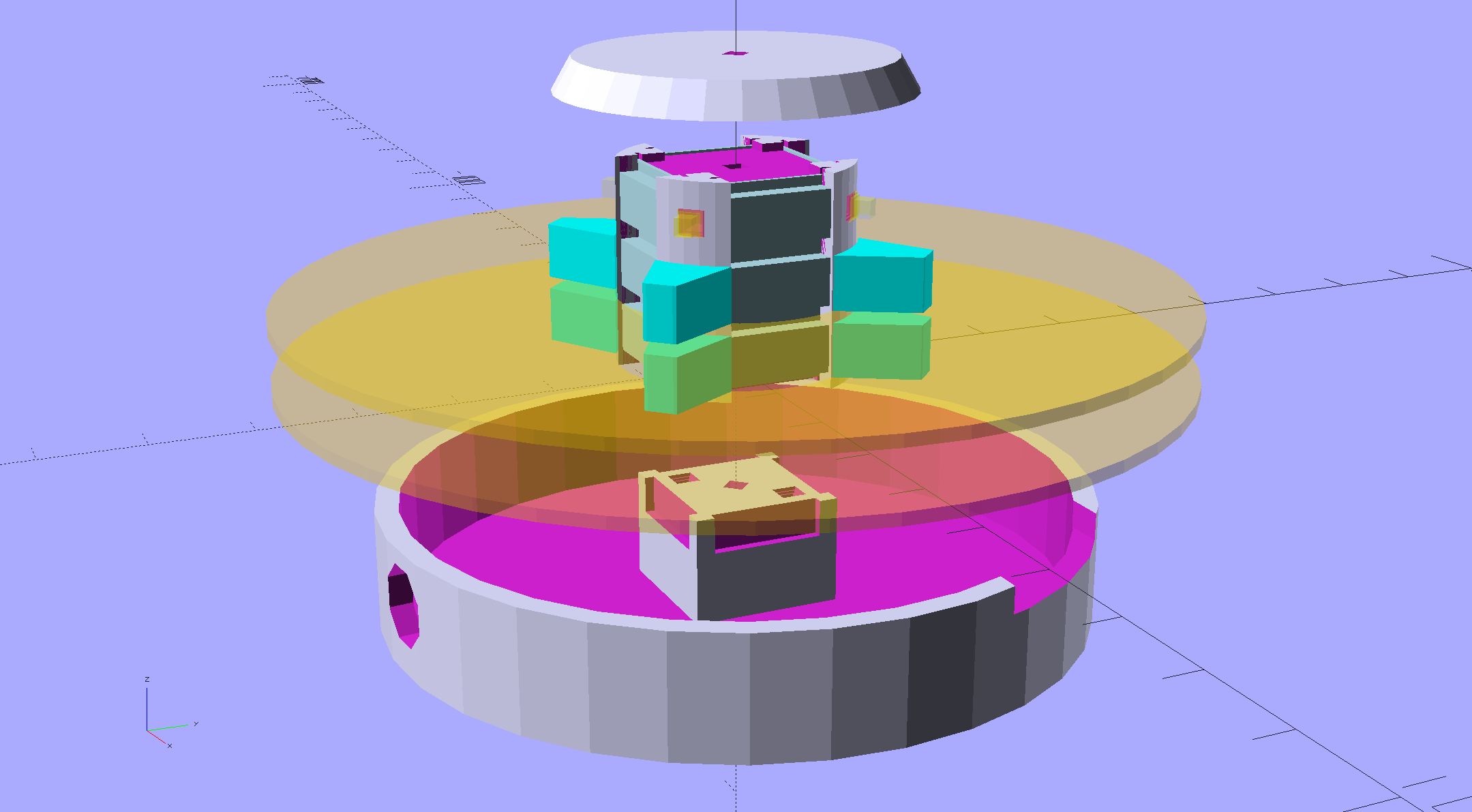
An improved version of the 3D printed plastic bits going into the Hard Drive Platter Mood Light:
Hard Drive Mood Light – improved – solid model – Show view
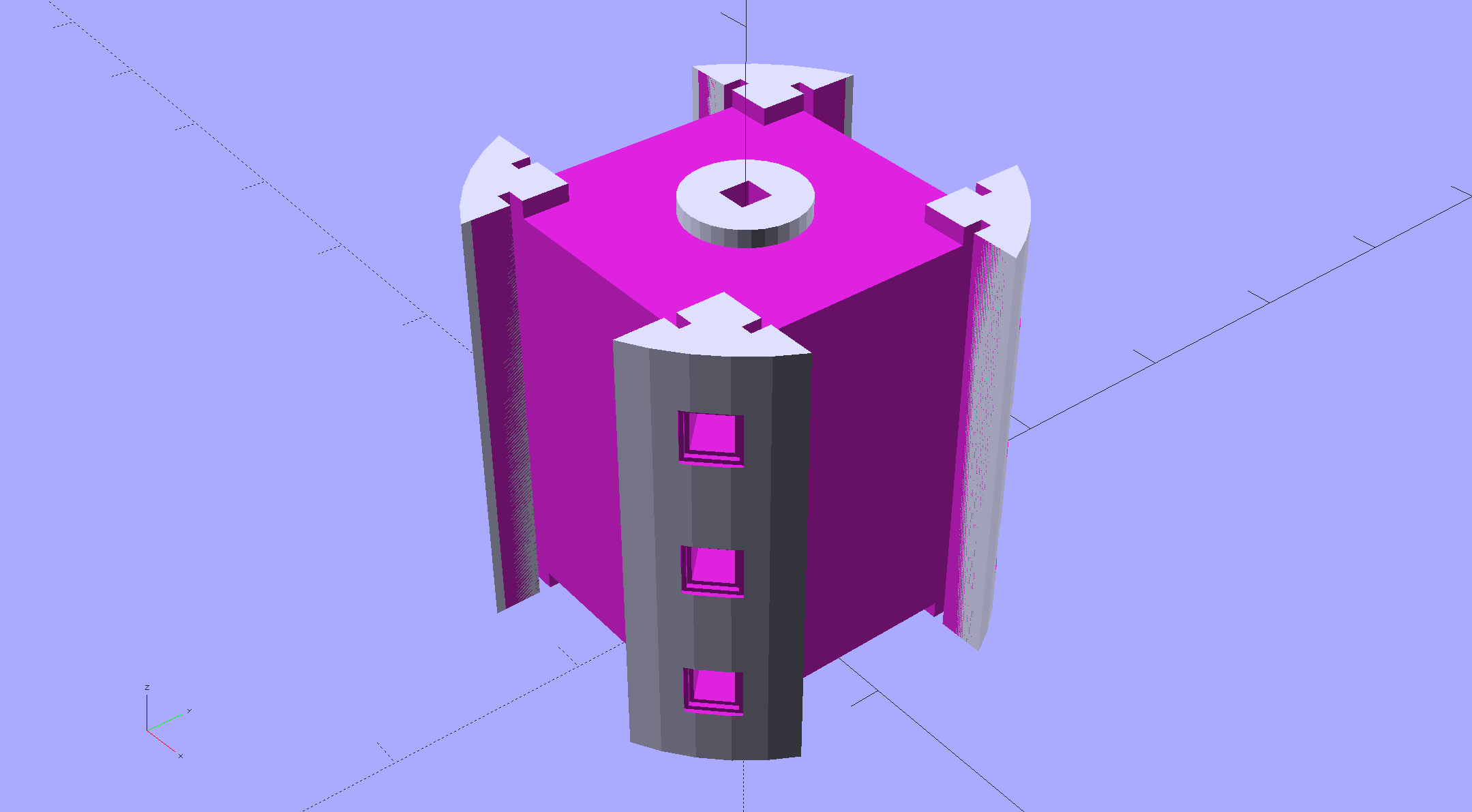
The central pillar now has cutouts behind the Neopixel strips so you (well, I) can solder directly to the larger half-pads on the back, plus a boss on the top for better wire management:
Hard Drive Mood Light – improved – Pillar – solid model
I’m not entirely satisfied with the little slots for the strip edges; the resolution limits of 3D printing call for larger openings, but there’s not much meat around those pins up the edge.
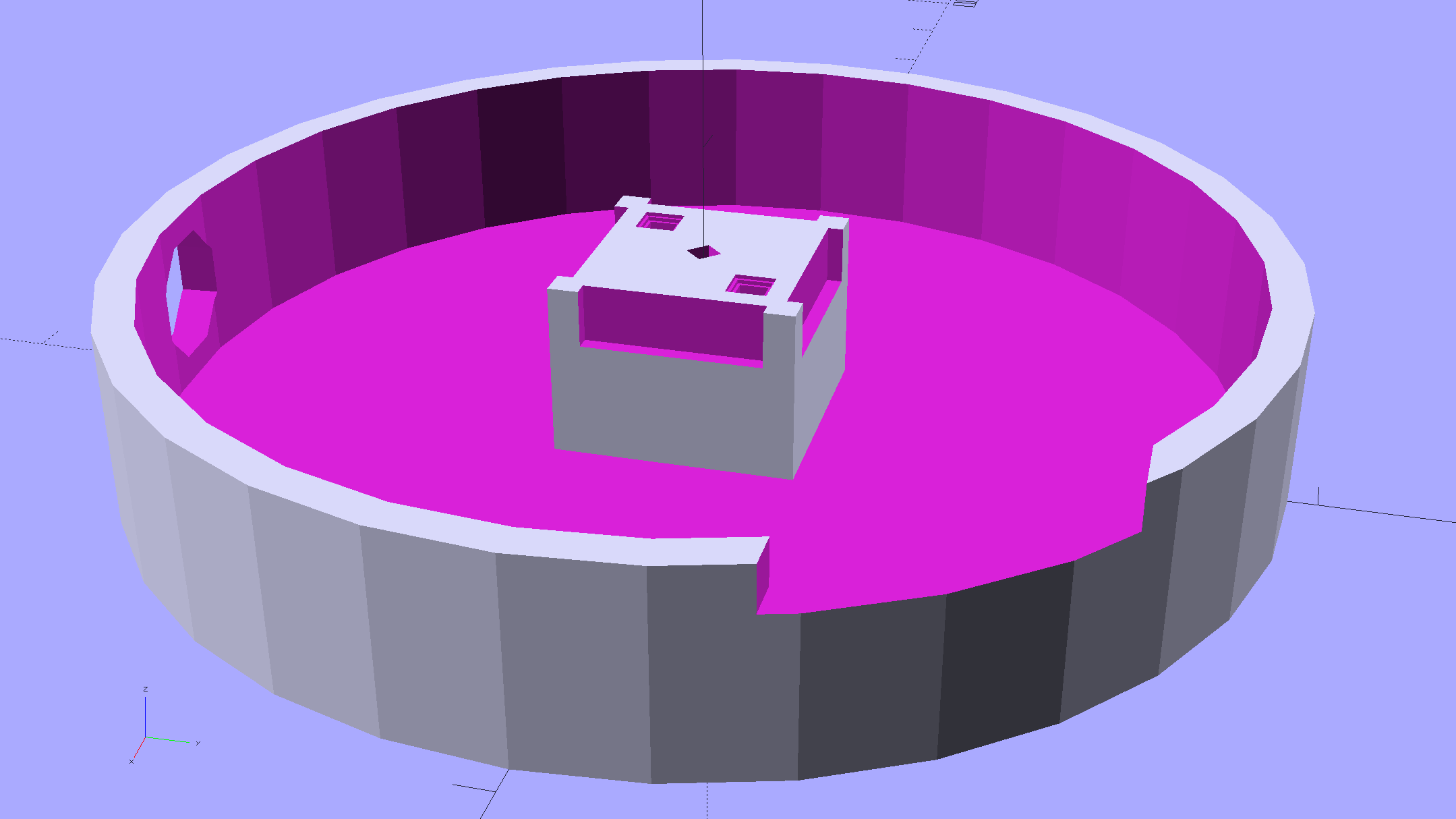
The base becomes much larger to hold the Arduino Pro Mini and gains an optional slot to let the programming cable reach the outside:
Hard Drive Mood Light – improved – Base – solid model
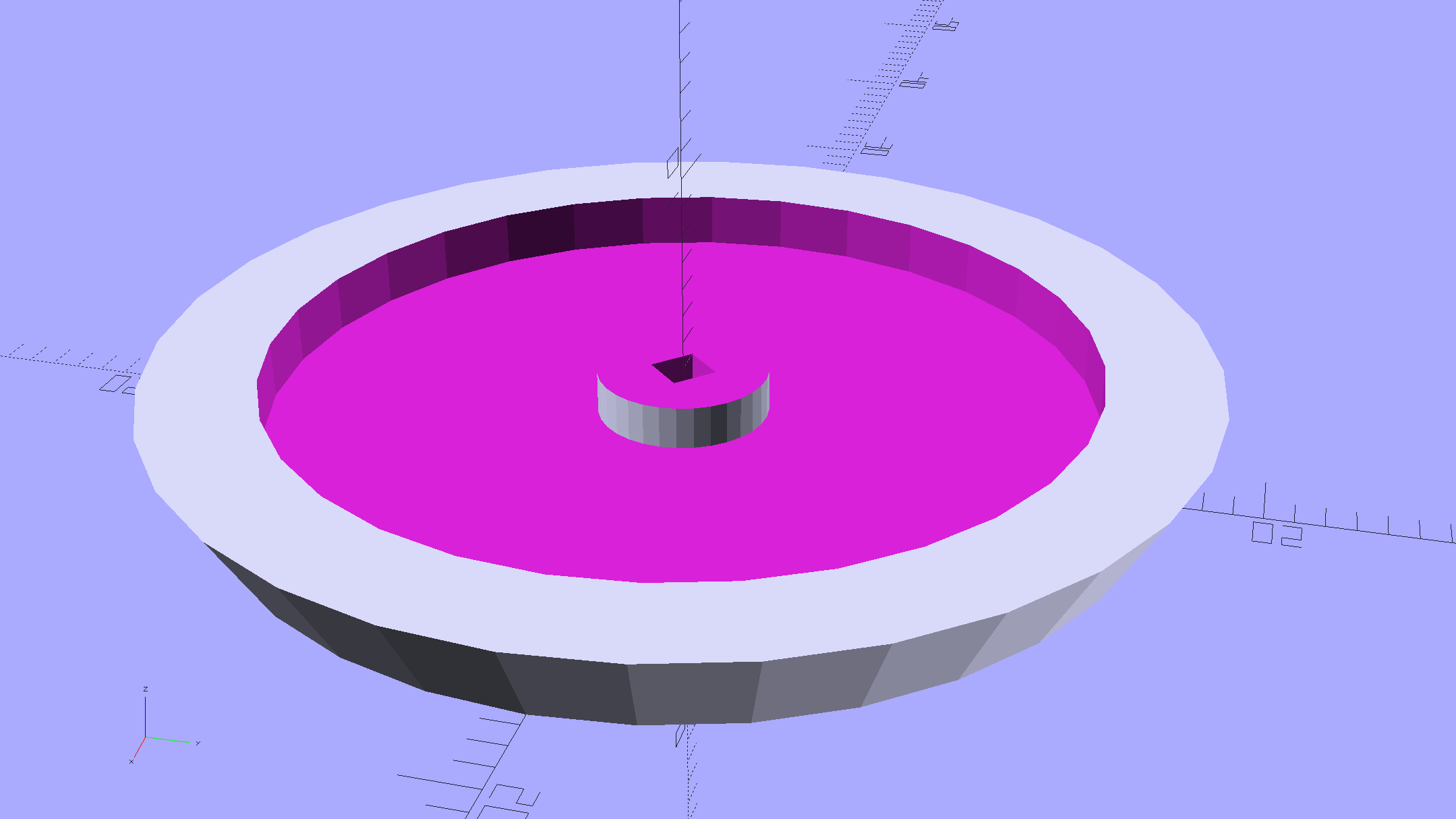
The cap has a boss matching the one atop the pillar:
Hard Drive Mood Light – improved – Cap – solid model
Both the cap & base have center features recessed by two thread thicknesses to let their rims apply a slight clamping force on the platters.
Our Larval Engineer says it really needs an internal battery with maybe four hours of runtime, a charging base station (ideally with inductive power transfer), buttons (or, better, a tilt switch / accelerometer) for mode selection, and perhaps a microphone to synchronize lighting effects with music. To my horror, her co-op job seems to have exposed her to Marketeers…
We do, however, agree that the Cap would look better in lathe-turned brass with a non-tarnish clearcoat.
The OpenSCAD source code:
// Hard Drive Platter Mood Light
// Ed Nisley KE4ZNU November 2015

Layout = "Spacers";					// Build Show Pixel LEDString Platters Pillar Spacers TopCap Base

CablePort = true;

ShowDisks = 2;						// number of disks in Show layout

//- Extrusion parameters must match reality!

ThreadThick = 0.25;
ThreadWidth = 0.40;

HoleWindage = 0.2;

Protrusion = 0.1;			// make holes end cleanly

inch = 25.4;

function IntegerMultiple(Size,Unit) = Unit * ceil(Size / Unit);

//----------------------
// Dimensions

ID = 0;
OD = 1;
LENGTH = 2;

Platter = [25.0,95.0,1.27];						// hard drive platters - must match actual thickness!

LEDStringCount = 3;								// number of LEDs on each strip
LEDStripCount = 4;								// number of strips (verify locating pin holes & suchlike)

WireSpace = 1.0;								// allowance for wiring along strip ends

Pixel = [13.0, 1000 / 144, 0.6];				// smallest indivisible unit of LED strip
PixelMargin = [1.0, 1.0, 2.0];					// LED and circuitry atop the strip

BeamAngle = 120;								// LED viewing angle
BeamShape = [
	[0,0],
	[Platter[OD]*cos(BeamAngle/2),-Platter[OD]*sin(BeamAngle/2)],
	[Platter[OD]*cos(BeamAngle/2), Platter[OD]*sin(BeamAngle/2)]
];

PillarSides = 12*4;

PillarCore = Platter[ID] - 2*(Pixel[2] + PixelMargin[2] + 2.0);		// LED channel distance across pillar centerline
PillarLength = LEDStringCount*Pixel[1] + Platter[LENGTH];
echo(str("Pillar core size: ",PillarCore));
echo(str("      ... length:"),PillarLength);

PCB = [34.5,17.5,1.6];								// Arduino Pro Mini (or whatever) PCB size
PCBClearTop = 5.0;
PCBClearBot = 5.0;
PCBHeight = PCB[2] + PCBClearBot + PCBClearTop;

PCBRadius = sqrt(pow(Platter[ID]/2 + PCB[1],2) + pow(PCB[0]/2,2));
echo(str("PCB Corner radius: ",PCBRadius));

CoaxConn = [7.8,11.2,5.0];							// power connector

Cap = [Platter[ID] + 4.0,Platter[ID] + 4.0 + 10*2*ThreadWidth,2*WireSpace + 6*ThreadThick];		// cap over top of pillar
CapSides = 8*4;

BaseClearHeight = max(PCBHeight,CoaxConn[OD]);

Base = [2.0 + 2*PCBRadius,2.0 + 2*PCBRadius + CoaxConn[LENGTH],BaseClearHeight + 6*ThreadThick];
BaseSides = 8*4;

Screw = [1.5,2.0,20.0];							// screws used to secure cap & pillar

Spacer = [Platter[ID],(Platter[ID] + 2*8),(Pixel[1] - Platter[LENGTH])];
echo(str("Spacer  OD: ",Spacer[OD]));
echo(str(" ... thick:",Spacer[LENGTH]));

LEDStripProfile = [
	[0,0],
	[Pixel[0]/2,0],
	[Pixel[0]/2,Pixel[2]],
	[(Pixel[0]/2 - PixelMargin[0]),Pixel[2]],
	[(Pixel[0]/2 - PixelMargin[0]),(Pixel[2] + PixelMargin[2])],
	[-(Pixel[0]/2 - PixelMargin[0]),(Pixel[2] + PixelMargin[2])],
	[-(Pixel[0]/2 - PixelMargin[0]),Pixel[2]],
	[-Pixel[0]/2,Pixel[2]],
	[-Pixel[0]/2,0]
];

//----------------------
// Useful routines

module PolyCyl(Dia,Height,ForceSides=0) {			// based on nophead's polyholes

  Sides = (ForceSides != 0) ? ForceSides : (ceil(Dia) + 2);

  FixDia = Dia / cos(180/Sides);

  cylinder(r=(FixDia + HoleWindage)/2,
		h=Height,
	$fn=Sides);
}

//- Locating pin hole with glue recess
//  Default length is two pin diameters on each side of the split

PinOD = 1.70;

module LocatingPin(Dia=PinOD,Len=0.0) {

	PinLen = (Len != 0.0) ? Len : (4*Dia);

	translate([0,0,-ThreadThick])
		PolyCyl((Dia + 2*ThreadWidth),2*ThreadThick,4);

	translate([0,0,-2*ThreadThick])
		PolyCyl((Dia + 1*ThreadWidth),4*ThreadThick,4);

	translate([0,0,-(PinLen/2 + ThreadThick)])
		PolyCyl(Dia,(PinLen + 2*ThreadThick),4);

}
//----------------------
// Pieces

//-- LED strips

module OnePixel() {

	render()
		rotate([-90,0,0]) rotate(180)				// align result the way you'd expect from the dimensions
			difference() {
				linear_extrude(height=Pixel[1],convexity=3)
					polygon(points=LEDStripProfile);
				translate([-Pixel[0]/2,Pixel[2],-PixelMargin[0]])
					cube([Pixel[0],2*PixelMargin[2],2*PixelMargin[0]]);
				translate([-Pixel[0]/2,Pixel[2],Pixel[1]-PixelMargin[0]])
					cube([Pixel[0],2*PixelMargin[2],2*PixelMargin[0]]);
			}
}

module LEDString(n = LEDStringCount) {

	for (i=[0:n-1])
		translate([0,i*Pixel[1]])
//			resize([0,Pixel[1] + 2*Protrusion,0])
				OnePixel();
}

//-- Stack of hard drive platters

module Platters(n = LEDStringCount + 1) {

	color("gold",0.4)
	for (i=[0:n-1]) {
		translate([0,0,i*Pixel[1]])
			difference() {
				cylinder(d=Platter[OD],h=Platter[LENGTH],center=false,$fn=PillarSides);
				cylinder(d=Platter[ID],h=3*Platter[LENGTH],center=true,$fn=PillarSides);
			}
	}
}

//-- Pillar holding the LED strips

module Pillar() {

	difflen = PillarLength + 2*Protrusion;

//	render(convexity=5)
	difference() {
		linear_extrude(height=PillarLength,convexity=4)
			difference() {
				rotate(180/(12*4))
					circle(d=Platter[ID] - 1*ThreadWidth,$fn=PillarSides);

				for (i=[0:LEDStripCount-1]) 					// clearance for LED beamwidth, may not actually cut surface
					rotate(i*360/LEDStripCount)
						translate([PillarCore/2,0,0])
							polygon(points=BeamShape);

				for (i=[0:LEDStripCount-1])						// LED front clearance
					rotate(i*360/LEDStripCount)
						translate([(PillarCore/2 + Pixel[2]),(Pixel[0] - 2*PixelMargin[0])/2])
							rotate(-90)
								square([Pixel[0] - 2*PixelMargin[0],Platter[ID]]);

			}

		for (i=[0:LEDStripCount-1])								// LED strip slots
			rotate(i*360/LEDStripCount)
				translate([PillarCore/2,0,-Protrusion])
					linear_extrude(height=difflen,convexity=2)
						rotate(-90)
							polygon(points=LEDStripProfile);

		difference() {											// wiring recess on top surface, minus boss
			for (i=[0,90])
				rotate(i)
					translate([0,0,(PillarLength - (WireSpace/2 - Protrusion))])
						cube([(PillarCore + 2*Protrusion),Pixel[0] - 2*PixelMargin[0],WireSpace],center=true);
			cylinder(d=3*Screw[OD],h=PillarLength + Protrusion,$fn=CapSides);
		}

		for (i=[0:LEDStripCount-1])								// wiring recess on bottom surface
			rotate(i*90)
				translate([PillarCore/2 - (WireSpace - Protrusion)/2,0,WireSpace/2 - Protrusion])
					cube([WireSpace + Protrusion,Pixel[0] - 2*PixelMargin[0],WireSpace],center=true);

		for (j=[0:LEDStringCount-1])							// platter spacer alignment pins
			for (i=[0:LEDStripCount-1])
				rotate(i*360/LEDStripCount + 180/LEDStripCount)
					translate([(Platter[ID] - 1*ThreadWidth)/2,0,(j*Pixel[1] + Pixel[1]/2 + Platter[LENGTH]/2)])
						rotate([0,90,0])
							rotate(45)
								LocatingPin();

		translate([0,0,-Protrusion])							// central screw hole
			rotate(180/4)
				PolyCyl(Screw[ID],difflen,4);

		if (false)
		for (i=[-1,1])											// vertical wire channels
			rotate(i*360/LEDStripCount + 180/LEDStripCount)
				translate([PillarCore/2 - 2.0,0,-Protrusion])
					PolyCyl(2.0,difflen,4);

		for (i=[-1,1])											// locating pins
			rotate(i*360/LEDStripCount - 180/LEDStripCount)
				translate([PillarCore/2 - 2.0,0,0])
					LocatingPin();
	}
}

//-- Spacers to separate platters

module Spacers() {

	difference() {
		linear_extrude(height=Spacer[LENGTH],convexity=4)
			difference() {
				rotate(180/PillarSides)
					circle(d=Spacer[OD],$fn=PillarSides);

				for (i=[0:LEDStripCount-1]) 					// clearance for LED beamwidth, may not actually cut surface
					rotate(i*360/LEDStripCount)
						translate([PillarCore/2,0,0])
							polygon(points=BeamShape);

				for (i=[0:LEDStripCount-1])						// LED front clearance
					rotate(i*360/LEDStripCount)
						translate([(PillarCore/2 + Pixel[2]),(Pixel[0] - 2*PixelMargin[0])/2])
							rotate(-90)
								square([Pixel[0] - 2*PixelMargin[0],Platter[ID]]);


				rotate(180/PillarSides)
					circle(d=Spacer[ID],$fn=PillarSides);		// central pillar fits in the hole
			}

		for (i=[0:LEDStripCount-1])
			rotate(i*360/LEDStripCount + 180/LEDStripCount)
				translate([Platter[ID]/2,0,(Pixel[1] - Platter[LENGTH])/2])
					rotate([0,90,0])
						rotate(45)
							LocatingPin();

	}
}

//-- Cap over top of pillar

module TopCap() {

	difference() {
		cylinder(d1=(Cap[OD] + Cap[ID])/2,d2=Cap[OD],h=Cap[LENGTH],$fn=CapSides);		// outer lid

		translate([0,0,-Protrusion])
			PolyCyl(Screw[ID],Cap[LENGTH] + WireSpace + Protrusion,4);					// screw hole

		translate([0,0,Cap[LENGTH] - 2*WireSpace])
			difference() {
				cylinder(d=Cap[ID],h=2*Cap[LENGTH],$fn=CapSides);						// cutout
				cylinder(d=3*Screw[OD],h=Cap[LENGTH],$fn=CapSides);						// boss
			}

		translate([0,0,Cap[LENGTH] - 2*ThreadThick])
			cylinder(d=Cap[ID]/2,h=2*ThreadThick + Protrusion,$fn=CapSides);			// recess boss
	}
}

//-- Base below pillar

module Base() {

	SideWidth = 0.5*Base[OD]*sin(180/BaseSides);						// close enough

	difference() {
		union() {
			difference() {
				cylinder(d=Base[OD],h=Base[LENGTH],$fn=BaseSides);			// outer base

				translate([0,0,6*ThreadThick])								// main cutout
					cylinder(d=Base[ID],h=Base[LENGTH],$fn=BaseSides);

				rotate(180/BaseSides)
					translate([0,0,Base[LENGTH] - BaseClearHeight/2]) 					// power connector hole
						rotate([90,0,0]) rotate(180/8)
							PolyCyl(CoaxConn[ID],Base[OD],8);
			}

			translate([0,0,Base[LENGTH]/2])									// recess pillar support below rim
				cube([PillarCore,PillarCore,Base[LENGTH] - 2*ThreadThick],center=true);
		}

		for (i=[0:LEDStripCount-1])											// wiring recesses
			rotate(i*90)
				translate([PillarCore/2 - (WireSpace - Protrusion)/2,0,Base[LENGTH] - 4*WireSpace/2])
					cube([WireSpace + Protrusion,PillarCore - 4*WireSpace,4*WireSpace],center=true);

		translate([0,0,-Protrusion])
			PolyCyl(Screw[ID],2*Base[LENGTH],4);						// screw hole

		translate([0,0,-Protrusion])									// screw head recess
			rotate(180/8)
				PolyCyl(8.5,Base[LENGTH] - 3.0 + Protrusion,8);

		for (i=[-1,1])													// locating pins
			rotate(i*360/LEDStripCount - 180/LEDStripCount)
				translate([PillarCore/2 - 2.0,0,Base[LENGTH] - ThreadThick])
					LocatingPin();

		if (CablePort)
			translate([0,Platter[ID]/2 + PCB[1],Base[LENGTH] - 3.0 + Protrusion])
				rotate(-90)
					cube([PCB[1],Base[OD],3.0]);

	}

}

//----------------------
// Build it

if (Layout == "Pixel")
	OnePixel();

if (Layout == "LEDString")
	LEDString(LEDStringCount);

if (Layout == "Platters")
	Platters(LEDStringCount + 1);

if (Layout == "Pillar")
	Pillar(LEDStringCount);

if (Layout == "TopCap")
	TopCap();

if (Layout == "Base")
	Base();

if (Layout == "Spacers")
	Spacers();

if (Layout == "Show") {
	Pillar();

	for (i=[0:LEDStripCount-1])											// LED strips
		rotate(i*360/LEDStripCount)
			translate([PillarCore/2,0,Platter[LENGTH]/2])
				rotate([90,0,90])
					color("lightblue") LEDString();
	if (true)
	for (j=[0:max(1,ShowDisks - 2)])									// spacers
		translate([0,0,(j*Pixel[1] + Platter[LENGTH])])
			color("cyan") Spacers();

	for (j=[0:max(2,ShowDisks - 2)])										// spacer alignment pins
		for (i=[0:LEDStripCount-1])
			rotate(i*360/LEDStripCount + 180/LEDStripCount)
				translate([(Platter[ID] - 1*ThreadWidth)/2,0,(j*Pixel[1] + Pixel[1]/2 + Platter[LENGTH]/2)])
					rotate([0,90,0])
						rotate(45)
							 color("Yellow",0.25) LocatingPin(Len=4);
	translate([0,0,PillarLength + 3*Cap[LENGTH]])
		rotate([180,0,0])
			TopCap();

	translate([0,0,-2*Base[LENGTH]])
		Base();

	if (ShowDisks > 0)
		Platters(ShowDisks);

}

// Ad-hoc build layout

if (Layout == "Build") {
	if (true)
		Pillar();

	if (true)
		translate([0,(Platter[ID] + Cap[OD])/2,0])
			TopCap();

	if (true)
		translate([0,-(Platter[ID] + Base[OD])/2,0])
			Base();

	Ybase = Spacer[OD] * (LEDStringCount%2 ? (LEDStringCount - 1) : (LEDStringCount - 2)) / 4;
	if (true)
		for (i=[0:LEDStringCount])										// build one extra set of spacers!
			translate([(i%2 ? 1 : -1)*(Spacer[OD] + Base[OD])/2,		// alternate X sides to shrink Y space
					(i%2 ? i-1 : i)*Spacer[OD]/2 - Ybase,				// same Y for even-odd pairs in X
					0])
				Spacers();
}
So Time Warner updated the infrastructure upstream of Mary’s folks and installed a new cable modem / router, which killed my remote access using ssh (with RSA keys, passphrases, nonstandard ports, fixed internal IP addresses, port forwarding, port triggers, and all the Right Stuff). I just spent a harried pair of days trying and failing to figure out how to make this work again.
My laptop can ssh into my file server from our house network, both wired and wireless. Ditto when it’s on the Squidwrench Operating Table. Ditto from the low-quality Hampton Inn WiFi near her folks. Plunked on their desk and jacked into their router, however, that outbound ssh times out somewhere between their bits and my basement.
I dinked with the TW Surfboard modem / router, added the appropriate port forwarding & triggers, dialed back the firewall intensity, and ssh flat out doesn’t work in either direction from any PC (all running various Linus flavors). No diagnostics, no logs, nothing that I could find.
From the outside (our house or the Hampton), there’s no response from the PCs inside (on their desk). I’m not trying a loopback from inside to inside, which I know doesn’t work with consumer-grade routers. I’d planned to ssh from there to my basement file server, then ssh back to verify that the connections worked, but the outbound connection doesn’t work.
Probably unrelated, but equally frustrating: trying to configure Thunderbird’s outbound SMTP with their email server flat-out doesn’t work. Either the username / password isn’t valid (it is), various combination of ports / security / encryption (including the ones in the TW FAQs) don’t survive the configuration test, or a seemingly valid configuration doesn’t actually transmit email. Incoming email works only in IMAP mode, not POP3.
I finally set up outbound TW email to bankshot through his Gmail account, which will probably have unforeseen side effects.
The usual Google searches were unavailing, other than several notes suggesting that if you have any other choice of ISP or email provider than TW, do that. But it’s not like they have any choice; Verizon provides 1 Mb/s (!) DSL in that area and satellite Internet isn’t going to happen in an apartment.
Obviously, I’m doing several things wrong, but I have no idea what else to try. I’ve set up email and remote access often enough to get a whole bunch of things right, but that sure didn’t help with TW.