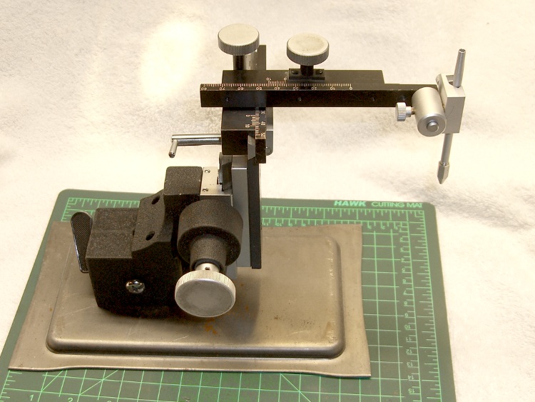
I’ll be giving an in-depth talk about my adventures restoring that old HP 7475A plotter for the Poughkeepsie ACM Chapter at Marist College this evening:
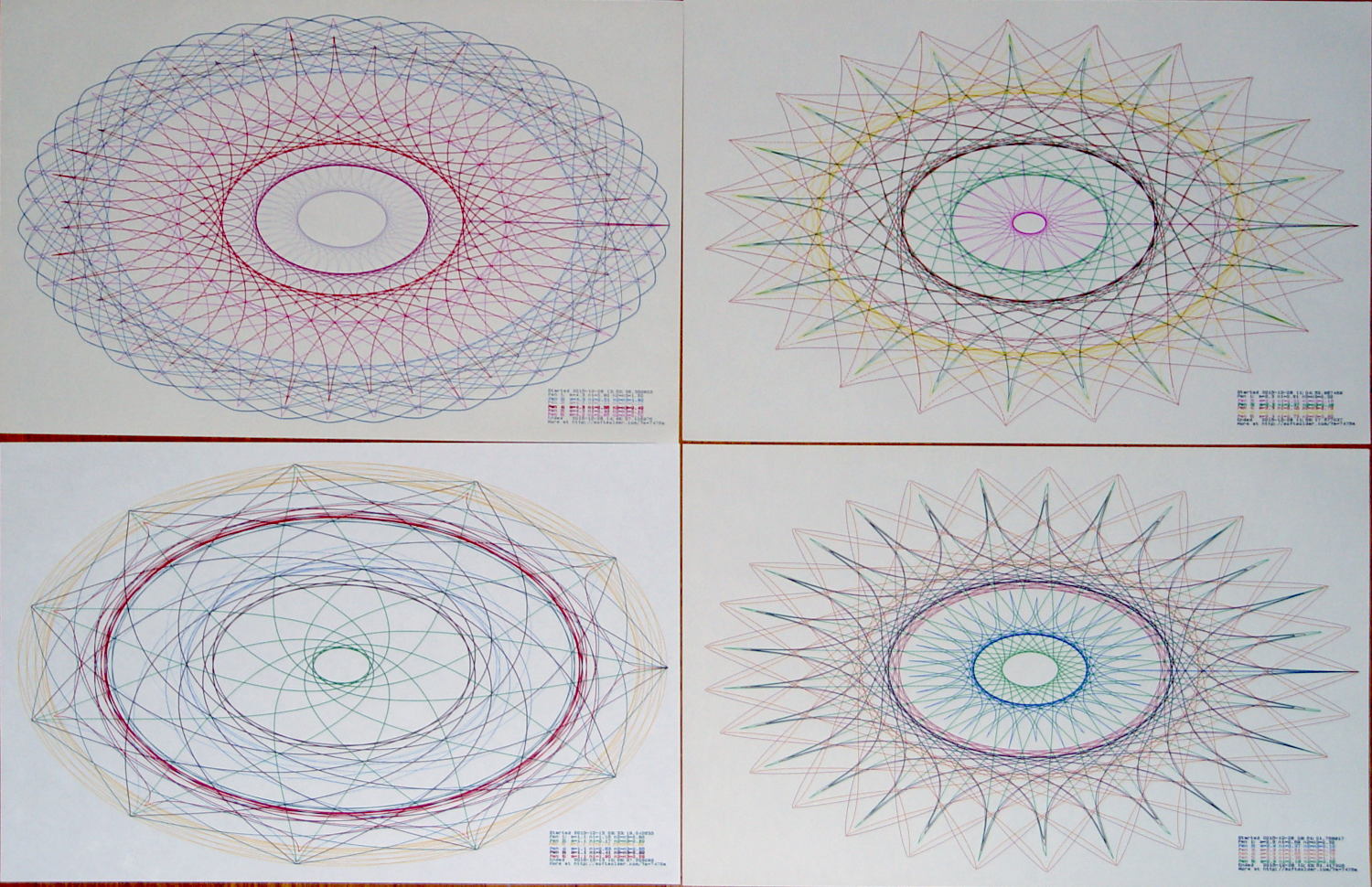
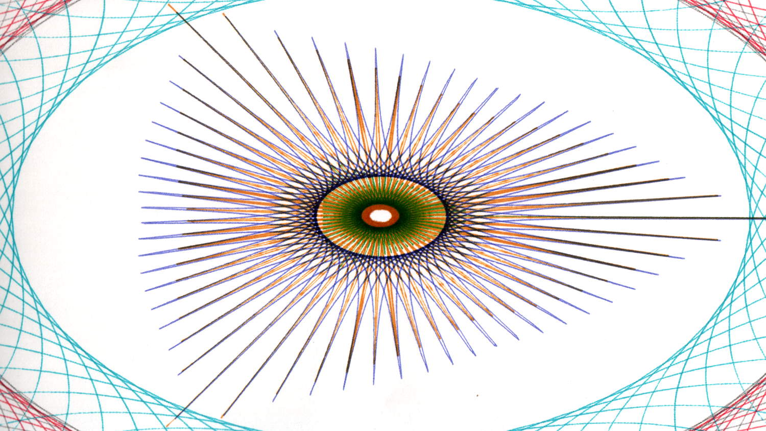
This being the Association for Computing Machinery, I will talk a bit about the Superformula that makes it all possible:

The presentation will look a lot like this: ACM – Plotting Like Its 1989. The PDF doesn’t include my patter, but perhaps the linky love on each screen can fill in the details.
If you’re following along, the Python source code running on the plotter as a GitHub Gist:
This file contains hidden or bidirectional Unicode text that may be interpreted or compiled differently than what appears below. To review, open the file in an editor that reveals hidden Unicode characters.
Learn more about bidirectional Unicode characters
| from chiplotle import * | |
| from math import * | |
| from datetime import * | |
| from time import * | |
| from types import * | |
| import random | |
| def superformula_polar(a, b, m, n1, n2, n3, phi): | |
| ''' Computes the position of the point on a | |
| superformula curve. | |
| Superformula has first been proposed by Johan Gielis | |
| and is a generalization of superellipse. | |
| see: http://en.wikipedia.org/wiki/Superformula | |
| Tweaked to return polar coordinates | |
| ''' | |
| t1 = cos(m * phi / 4.0) / a | |
| t1 = abs(t1) | |
| t1 = pow(t1, n2) | |
| t2 = sin(m * phi / 4.0) / b | |
| t2 = abs(t2) | |
| t2 = pow(t2, n3) | |
| t3 = -1 / float(n1) | |
| r = pow(t1 + t2, t3) | |
| if abs(r) == 0: | |
| return (0, 0) | |
| else: | |
| # return (r * cos(phi), r * sin(phi)) | |
| return (r, phi) | |
| def supershape(width, height, m, n1, n2, n3, | |
| point_count=10 * 1000, percentage=1.0, a=1.0, b=1.0, travel=None): | |
| '''Supershape, generated using the superformula first proposed | |
| by Johan Gielis. | |
| – `points_count` is the total number of points to compute. | |
| – `travel` is the length of the outline drawn in radians. | |
| 3.1416 * 2 is a complete cycle. | |
| ''' | |
| travel = travel or (10 * 2 * pi) | |
| # compute points… | |
| phis = [i * travel / point_count | |
| for i in range(1 + int(point_count * percentage))] | |
| points = [superformula_polar(a, b, m, n1, n2, n3, x) for x in phis] | |
| # scale and transpose… | |
| path = [] | |
| for r, a in points: | |
| x = width * r * cos(a) | |
| y = height * r * sin(a) | |
| path.append(Coordinate(x, y)) | |
| return Path(path) | |
| # RUN DEMO CODE | |
| if __name__ == '__main__': | |
| override = False | |
| plt = instantiate_plotters()[0] | |
| # plt.write('IN;') | |
| if plt.margins.soft.width < 11000: # A=10365 B=16640 | |
| maxplotx = (plt.margins.soft.width / 2) – 100 | |
| maxploty = (plt.margins.soft.height / 2) – 150 | |
| legendx = maxplotx – 2900 | |
| legendy = -(maxploty – 750) | |
| tscale = 0.45 | |
| numpens = 4 | |
| # prime/10 = number of spikes | |
| m_values = [n / 10.0 for n in [11, 13, 17, 19, 23]] | |
| # ring-ness 0.1 to 2.0, higher is larger | |
| n1_values = [ | |
| n / 100.0 for n in range(55, 75, 2) + range(80, 120, 5) + range(120, 200, 10)] | |
| else: | |
| maxplotx = plt.margins.soft.width / 2 | |
| maxploty = plt.margins.soft.height / 2 | |
| legendx = maxplotx – 3000 | |
| legendy = -(maxploty – 900) | |
| tscale = 0.45 | |
| numpens = 6 | |
| m_values = [n / 10.0 for n in [11, 13, 17, 19, 23, 29, 31, | |
| 37, 41, 43, 47, 53, 59]] # prime/10 = number of spikes | |
| # ring-ness 0.1 to 2.0, higher is larger | |
| n1_values = [ | |
| n / 100.0 for n in range(15, 75, 2) + range(80, 120, 5) + range(120, 200, 10)] | |
| print " Max: ({},{})".format(maxplotx, maxploty) | |
| # spiky-ness 0.1 to 2.0, higher is spiky-er (mostly) | |
| n2_values = [ | |
| n / 100.0 for n in range(10, 60, 2) + range(65, 100, 5) + range(110, 200, 10)] | |
| plt.write(chr(27) + '.H200:') # set hardware handshake block size | |
| plt.set_origin_center() | |
| # scale based on B size characters | |
| plt.write(hpgl.SI(tscale * 0.285, tscale * 0.375)) | |
| # slow speed for those abrupt spikes | |
| plt.write(hpgl.VS(10)) | |
| while True: | |
| # standard loadout has pen 1 = fine black | |
| plt.write(hpgl.PA([(legendx, legendy)])) | |
| pen = 1 | |
| plt.select_pen(pen) | |
| plt.write(hpgl.PA([(legendx, legendy)])) | |
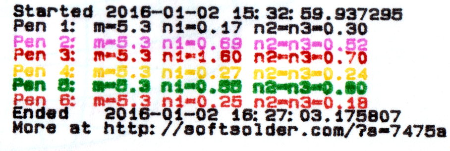
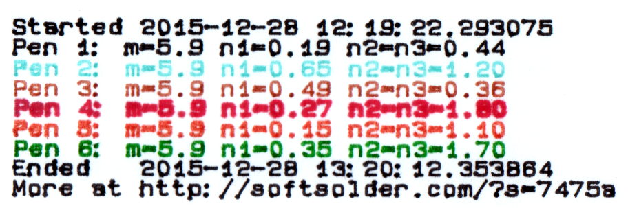
| plt.write(hpgl.LB("Started " + str(datetime.today()))) | |
| if override: | |
| m = 4.1 | |
| n1_list = [1.15, 0.90, 0.25, 0.59, 0.51, 0.23] | |
| n2_list = [0.70, 0.58, 0.32, 0.28, 0.56, 0.26] | |
| else: | |
| m = random.choice(m_values) | |
| n1_list = random.sample(n1_values, numpens) | |
| n2_list = random.sample(n2_values, numpens) | |
| pen = 1 | |
| for n1, n2 in zip(n1_list, n2_list): | |
| n3 = n2 | |
| print "{0} – m: {1:.1f}, n1: {2:.2f}, n2=n3: {3:.2f}".format(pen, m, n1, n2) | |
| plt.select_pen(pen) | |
| plt.write(hpgl.PA([(legendx, legendy – 100 * pen)])) | |
| plt.write( | |
| hpgl.LB("Pen {0}: m={1:.1f} n1={2:.2f} n2=n3={3:.2f}".format(pen, m, n1, n2))) | |
| e = supershape(maxplotx, maxploty, m, n1, n2, n3) | |
| plt.write(e) | |
| pen = pen + 1 if (pen % numpens) else 1 | |
| pen = 1 | |
| plt.select_pen(pen) | |
| plt.write(hpgl.PA([(legendx, legendy – 100 * (numpens + 1))])) | |
| plt.write(hpgl.LB("Ended " + str(datetime.today()))) | |
| plt.write(hpgl.PA([(legendx, legendy – 100 * (numpens + 2))])) | |
| plt.write(hpgl.LB("More at https://softsolder.com/?s=7475a")) | |
| plt.select_pen(0) | |
| plt.write(hpgl.PA([(-maxplotx,maxploty)])) | |
| print "Waiting for plotter… ignore timeout errors!" | |
| sleep(40) | |
| while NoneType is type(plt.status): | |
| sleep(5) | |
| print "Load more paper, then …" | |
| print " … Press ENTER on the plotter to continue" | |
| plt.clear_digitizer() | |
| plt.digitize_point() | |
| plotstatus = plt.status | |
| while (NoneType is type(plotstatus)) or (0 == int(plotstatus) & 0x04): | |
| plotstatus = plt.status | |
| print "Digitized: " + str(plt.digitized_point) | |