The Smell of Molten Projects in the Morning

Ed Nisley's Blog: Shop notes, electronics, firmware, machinery, 3D printing, laser cuttery, and curiosities. Contents: 100% human thinking, 0% AI slop.

Category: Software

General-purpose computers doing something specific

  • ITead Studio Quasi-Colorduino RGB LED Matrix Shield: Redesign Doodles

    Some notes on a recent acquisition that ought to allow random dots with individual brightness control (unlike my simple resistor-limited hack job):

    Color Shield - DM163 M54565 - demo
    Color Shield – DM163 M54565 – demo

    A Colorduino is a dedicated board that combines an Arduino-class microcontroller with hardware drivers for an 8×8 RGB LED matrix, with daisy-chaining I/O to build bigger displays. The Colors Shield you see above omits the Arduino circuitry and daisy-chaining hardware: it plugs atop an ordinary Arduino UNO-class board as a dedicated 8×8 tile driver.

    I do not profess to understand the ancestry & family tree of those designs and their various incarnations. This schematic doesn’t match the knockoff hardware in hand, which isn’t surprising after half a dozen years of relentless product cheapnification:

    ITeadStudio - RGB LED shield - DM163 M54564 - SPI notes
    ITeadStudio – RGB LED shield – DM163 M54564 – SPI notes

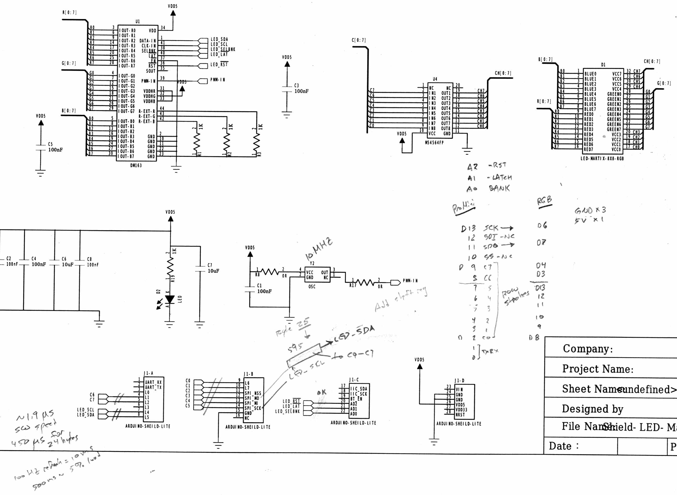
    It comes close enough for a big-picture overview…

    The DM163 has 8×3 constant current sink PWM pins that connect to the column cathodes of the RGB matrix. It provides either 8 or 6 bits of PWM control for each output, with either 6 or 8 bits of gamma correction to make the grayscale shades work out properly (those are separate shift registers and the PWM generators use both, so the chip doesn’t care how you divvy up the 14 bits).

    The three 1 kΩ resistors set the current to 60 mA per output pin. The LED matrix might support anywhere from  70 to 120 mA peak current per LED, but I doubt the supplied matrix matches any of the available datasheets. The total current depends on the number of LEDs lit on each row, so large dark areas are a Good Thing.

    The serial protocol looks enough like SPI to get by, with controls for Reset, Latch, and Bank Select.

    The board has no power supply other than the single Arduino VCC pin, so you’re looking at a peak of 24 x 60 mA = 1.44 A through that pin. The Arduino regulator must supply that load pretty much full-time, which is obviously a Bad Thing; plan on plenty of dark areas.

    The DM163 SPI connections don’t use the Arduino’s hardware SPI, so it’s full-frontal bit-banging all the way. Three DM163 control bits use a trio of analog inputs as digital outputs. No harm in that, works fine with the knockoff Neopixels.

    The M54564 is a PNP high-side driver converting logic-level inputs to the current required for the row anodes of the matrix. The eight input bits are non-contiguous across the Arduino’s digital outputs. You could turn on all the M54564 outputs at once, which would be a Bad Thing.

    You shift 24 bytes of RGB data into the DM163 and latch the data, then raise one of the M54564 inputs to enable a given row of LEDs, which light up with the corresponding colors.

    The bit-banged SPI runs at 1.9 µs/bit and sending all 24 bits to the DM163 requires 450 µs. With a 100 Hz refresh, that’s a mere 5% overhead, but the fact that the board soaks up essentially all the I/O pins means the Arduino isn’t not doing much else in the way of real-world interaction.

    The Arduino driver, of dubious provenance, sets Timer 0 for 100-ish Hz interrupts. Each interrupt shifts another batch of bytes into the DM163 and selects the appropriate row. The driver uses a double-buffered array that soaks up 2x8x8x3 = 384 bytes of precious RAM, in addition to a bunch of working storage.

    If I were (re)designing this board…

    A separate power input jack for the DM163 that might optionally feed the Arduino’s VIN raw power pin.

    Use the Arduino SPI hardware, dammit.

    Put an HC595 shift register behind the M54564, so you’d shift 24 + 8 = 32 bits into the board, then strobe the latches. That eliminates eight digital pins used as a parallel port.

    You’d surely want to disable the row driver while switching the column drivers to avoid ghosting, so figure on a separate output enable for the HC595. That tri-states the 595’s outputs; although the M54564 has internal pulldowns, it might need more.

    It’s entirely usable as-is, but sheesh it’d be so easy to do a better job. That wouldn’t be software compatible with all the Arduino Love for the existing boards out there; there’s no point.


  • Epson R380 Printer: Resetting the Waste Ink Counter Again

    The Epson R380 printer never gets turned off, so it rarely has a chance to complain. After a powerdown due to refreshing the UPS batteries, it lit up with the dreaded “Service required. Visit your friendly Epson repair center” message that indicates you should just throw the printer out, because replacing the internal ink absorber mats / draining the internal tank is, mmm, economically infeasible when you pay somebody else to do it.

    Having done this before, though, it’s almost easy…

    • Pop a PC with a Windows partition off the to-be-recycled stack
    • Boot System Rescue CD
    • Back up the partition to a junk hard drive, just for practice
    • Copy the subdirectory of sketchy utilities to the Windows drive
    • Boot Windows (with no network connection)
    • Run sketchy utility to reset the ink counter
    • Boot SRC, restore partition
    • Return hard drive & PC to their respective piles
    • Declare victory and move on

    This time, a sketchy utility that resembled the Official Epson Reset Program actually reset something and the printer started up normally. As before, however, the saved MBR didn’t match the on-disk MBR, suggesting that either I don’t understand how to save / restore the MBR or that something once again meddled with the MBR in between the backup and the restore.

    I’ve emptied the waste ink tank maybe three times since the last reset: plenty of ink down the drain. Fortunately, I loves me some good continuous-flow ink supply action…

    Sheesh & similar remarks.

  • Random LED Dots: Entropy Library for Moah Speed with Less Gimcrackery

    A discussion over the Squidwrench Operating Table about injecting entropy into VMs before / during their boot sequence reminded me that I wanted to try the Entropy library with my 8×8 RGB LED matrix:

    8x8 RGB LED Matrix - board overview
    8×8 RGB LED Matrix – board overview

    The original version trundled along with random numbers produced by timing Geiger counter ticks. The second version, digitizing the amplified noise from a reverse-biased PN junction, ran much faster.

    What’s new & different: the Entropy library measures the jitter between the ATmega328 watchdog timer’s RC oscillator and the ceramic resonator (on Pro Mini boards) driving the CPU. It cranks out four bytes of uncorrelated bits every half-second, which isn’t quite fast enough for a sparkly display, but re-seeding the Arduino PRNG whenever enough entropy arrives works well enough.

    One could, of course, re-seed the PRNG with Geiger bits or junction noise to the same effect. The key advantage of the Entropy library: no external hardware required. The downside: no external hardware required, so, minus those techie transistors / resistors / op amps, it will look like Just Another Arduino Project.

    Reverse-bias noise amplifier - detail
    Reverse-bias noise amplifier – detail

    Le sigh.

    In any event, the Entropy library has excellent documentation and works perfectly.

    The Arduino PRNG can produce results fast enough for wonderfully twinkly output that’s visually indistinguishable from the “true” random numbers from the Geiger counter or PN junction. I dialed it back to one update every 5 ms, because letting it free-run turned the display into an unattractive blur.

    The top trace shows the update actually happens every 6 ms:

    Entropy TRNG - LED update vs refresh
    Entropy TRNG – LED update vs refresh

    The lower trace shows that each matrix row refresh takes about a millisecond. Refreshes occur on every main loop iteration and interfere with the update, not that that makes any difference. Should it matter, subtract one from the update period and it’ll be all good.

    The Arduino source code as a GitHub Gist:

    // Random LED Dots
    // Based on Entropy library using watchdog timer jitter
    // https://sites.google.com/site/astudyofentropy/project-definition/timer-jitter-entropy-sources/entropy-library
    // Ed Nisley – KE4ANU – August 2016
    #include <Entropy.h>
    //———-
    // Pin assignments
    const byte PIN_HEARTBEAT = 8; // DO – heartbeat LED
    const byte PIN_SYNC = A3; // DO – scope sync
    const byte PIN_LATCH = 4; // DO – shift register latch clock
    const byte PIN_DIMMING = 9; // AO – LED dimming control
    // These are *hardware* SPI pins
    const byte PIN_MOSI = 11; // DO – data to shift reg
    const byte PIN_MISO = 12; // DI – data from shift reg (unused)
    const byte PIN_SCK = 13; // DO – shift clock to shift reg (also Arduino LED)
    const byte PIN_SS = 10; // DO – -slave select (must be positive for SPI output)
    //———-
    // Constants
    #define UPDATE_MS 5
    //———-
    // Globals
    // LED selects are high-active bits and low-active signals: flipped in UpdateLEDs()
    // *exactly* one row select must be active in each element
    typedef struct {
    const byte Row;
    byte ColR;
    byte ColG;
    byte ColB;
    } LED_BYTES;
    // altering the number of rows & columns will require substantial code changes…
    #define NUMROWS 8
    #define NUMCOLS 8
    LED_BYTES LEDs[NUMROWS] = {
    {0x80,0,0,0},
    {0x40,0,0,0},
    {0x20,0,0,0},
    {0x10,0,0,0},
    {0x08,0,0,0},
    {0x04,0,0,0},
    {0x02,0,0,0},
    {0x01,0,0,0},
    };
    byte RowIndex;
    #define LEDS_ON 0
    #define LEDS_OFF 255
    unsigned long MillisNow;
    unsigned long MillisThen;
    //– Helper routine for printf()
    int s_putc(char c, FILE *t) {
    Serial.write(c);
    }
    //– Useful stuff
    // Free RAM space monitor
    // From http://playground.arduino.cc/Code/AvailableMemory
    uint8_t * heapptr, * stackptr;
    void check_mem() {
    stackptr = (uint8_t *)malloc(4); // use stackptr temporarily
    heapptr = stackptr; // save value of heap pointer
    free(stackptr); // free up the memory again (sets stackptr to 0)
    stackptr = (uint8_t *)(SP); // save value of stack pointer
    }
    void TogglePin(char bitpin) {
    digitalWrite(bitpin,!digitalRead(bitpin)); // toggle the bit based on previous output
    }
    void PulsePin(char bitpin) {
    TogglePin(bitpin);
    TogglePin(bitpin);
    }
    //———
    //– SPI utilities
    void EnableSPI(void) {
    digitalWrite(PIN_SS,HIGH); // make sure this is high!
    SPCR |= 1 << SPE;
    }
    void DisableSPI(void) {
    SPCR &= ~(1 << SPE);
    }
    void WaitSPIF(void) {
    while (! (SPSR & (1 << SPIF))) {
    // TogglePin(PIN_HEARTBEAT);
    continue;
    }
    }
    byte SendRecSPI(byte Dbyte) { // send one byte, get another in exchange
    SPDR = Dbyte;
    WaitSPIF();
    return SPDR; // SPIF will be cleared
    }
    void UpdateLEDs(byte i) {
    SendRecSPI(~LEDs[i].ColB); // low-active outputs
    SendRecSPI(~LEDs[i].ColG);
    SendRecSPI(~LEDs[i].ColR);
    SendRecSPI(~LEDs[i].Row);
    analogWrite(PIN_DIMMING,LEDS_OFF); // turn off LED to quench current
    PulsePin(PIN_LATCH); // make new shift reg contents visible
    analogWrite(PIN_DIMMING,LEDS_ON);
    }
    //—————
    // Set LED from integer
    // On average, this leaves the LED unchanged for 1/8 of the calls…
    void SetLED(unsigned long Value) {
    byte Row = Value & 0x07;
    byte Col = (Value >> 3) & 0x07;
    byte Color = (Value >> 6) & 0x07;
    byte BitMask = (0x80 >> Col);
    // printf("%u %u %u %u\r\n",Row,Col,Color,BitMask);
    LEDs[Row].ColR &= ~BitMask;
    LEDs[Row].ColR |= (Color & 0x04) ? BitMask : 0;
    LEDs[Row].ColG &= ~BitMask;
    LEDs[Row].ColG |= (Color & 0x02) ? BitMask : 0;
    LEDs[Row].ColB &= ~BitMask;
    LEDs[Row].ColB |= (Color & 0x01) ? BitMask : 0;
    }
    //——————
    // Set things up
    void setup() {
    pinMode(PIN_HEARTBEAT,OUTPUT);
    digitalWrite(PIN_HEARTBEAT,HIGH); // show we arrived
    pinMode(PIN_SYNC,OUTPUT);
    digitalWrite(PIN_SYNC,LOW);
    pinMode(PIN_MOSI,OUTPUT); // SPI-as-output is not strictly necessary
    digitalWrite(PIN_MOSI,LOW);
    pinMode(PIN_SCK,OUTPUT);
    digitalWrite(PIN_SCK,LOW);
    pinMode(PIN_SS,OUTPUT);
    digitalWrite(PIN_SS,HIGH); // OUTPUT + HIGH is required to make SPI output work
    pinMode(PIN_LATCH,OUTPUT);
    digitalWrite(PIN_LATCH,LOW);
    Serial.begin(57600);
    fdevopen(&s_putc,0); // set up serial output for printf()
    printf("Random LED Dots – Watchdog Entropy\r\nEd Nisley – KE4ZNU – August 2016\r\n");
    Entropy.initialize(); // start up entropy collector
    //– Set up SPI hardware
    SPCR = B01110001; // Auto SPI: no int, enable, LSB first, master, + edge, leading, f/16
    SPSR = B00000000; // not double data rate
    EnableSPI(); // turn on the SPI hardware
    SendRecSPI(0); // set valid data in shift registers: select Row 0, all LEDs off
    //– Dimming pin must use fast PWM to avoid beat flicker with LED refresh rate
    // Timer 1: PWM 9 PWM 10
    analogWrite(PIN_DIMMING,LEDS_OFF); // disable column drive (hardware pulled it low before startup)
    TCCR1A = B10000001; // Mode 5 = fast 8-bit PWM with TOP=FF
    TCCR1B = B00001001; // … WGM, 1:1 clock scale -> 64 kHz
    //– lamp test: send a white flash through all LEDs
    printf("Lamp test begins: white flash each LED…");
    digitalWrite(PIN_HEARTBEAT,LOW); // turn off while panel blinks
    analogWrite(PIN_DIMMING,LEDS_ON); // enable column drive
    for (byte i=0; i<NUMROWS; i++) {
    for (byte j=0; j<NUMCOLS; j++) {
    LEDs[i].ColR = LEDs[i].ColG = LEDs[i].ColB = 0x80 >> j;
    for (byte k=0; k<NUMROWS; k++) {
    UpdateLEDs(k);
    delay(25);
    }
    LEDs[i].ColR = LEDs[i].ColG = LEDs[i].ColB = 0;
    }
    }
    UpdateLEDs(NUMROWS-1); // clear the last LED
    printf(" done!\r\n");
    //– Preload LEDs with random values
    digitalWrite(PIN_HEARTBEAT,LOW);
    uint32_t rn = Entropy.random();
    printf("Preloading LED array with seed: %08lx\r\n",rn);
    randomSeed(rn);
    for (byte Row=0; Row<NUMROWS; Row++) {
    for (byte Col=0; Col<NUMCOLS; Col++) { // Col runs backwards, but we don't care
    LEDs[Row].ColR |= random(2) << Col; // random(2) returns 0 or 1
    LEDs[Row].ColG |= random(2) << Col;
    LEDs[Row].ColB |= random(2) << Col;
    }
    UpdateLEDs(Row);
    }
    check_mem();
    printf("SP: %u HP: %u Free RAM: %u\r\n",stackptr,heapptr,stackptr – heapptr);
    printf("Running…\r\n");
    MillisThen = millis();
    }
    //——————
    // Run the test loop
    void loop() {
    unsigned long Hash;
    uint32_t rn;
    MillisNow = millis();
    // Re-seed the generator whenever we get enough entropy
    if (Entropy.available()) {
    digitalWrite(PIN_HEARTBEAT,HIGH);
    rn = Entropy.random();
    // printf("Random: %08lx ",rn);
    randomSeed(rn);
    digitalWrite(PIN_HEARTBEAT,LOW);
    }
    // If it's time for a change, whack a random LED
    if ((MillisNow – MillisThen) > UPDATE_MS) {
    MillisThen = MillisNow;
    SetLED(random());
    }
    // Refresh LED array to maintain the illusion of constant light
    UpdateLEDs(RowIndex++);
    if (RowIndex >= NUMROWS) {
    RowIndex = 0;
    PulsePin(PIN_SYNC);
    }
    }
    view raw TimerDots.ino hosted with ❤ by GitHub
  • Kenmore Progressive Vacuum Tool Adapters: First Failure

    I picked up a horsehair dust brush from eBay as a lightweight substitute for the Electrolux aluminum ball, discovered that an adapter I’d already made fit perfectly, did the happy dance, and printed one for the brush. That worked perfectly for half a year, whereupon:

    Dust Brush Adapter - broken parts
    Dust Brush Adapter – broken parts

    It broke about where I expected, along the layer lines at the cross section where the snout joins the fitting. You can see the three perimeter shells I hoped would strengthen the part:

    Dust Brush Adapter - layer separation
    Dust Brush Adapter – layer separation

    That has the usual 15% 3D Honeycomb infill, although there’s not a lot area for infill.

    There’s obviously a stress concentration there and making the wall somewhat thicker (to get more plastic-to-plastic area) might suffice. I’m not convinced the layer bonding would be good enough, even with more wall area, to resist the stress; that’s pretty much a textbook example of how & where 3D printed parts fail.

    That cross section should look like this:

    Dust Brush Adapter - Snout infill - Slic3r preview
    Dust Brush Adapter – Snout infill – Slic3r preview

    Anyhow, I buttered the snout’s broken end with JB Kwik epoxy, aligned the parts, and clamped them overnight:

    Dust Brush Adapter - clamping
    Dust Brush Adapter – clamping

    The source code now has a separate solid model for the dust brush featuring a slightly shorter snout; if when the epoxy fails, we’ll see how that changes the results. I could add ribs and suchlike along the outside, none of which seem worth the effort right now. Fairing the joint between those two straight sections would achieve the same end, with even more effort, because OpenSCAD.

    The OpenSCAD source code as a GitHub Gist:

    // Kenmore vacuum cleaner nozzle adapters
    // Ed Nisley KE4ZNU August 2016
    // Layout options
    Layout = "DustBrush"; // MaleFitting CoilWand FloorBrush CreviceTool ScrubbyTool LuxBrush DustBrush
    //- Extrusion parameters must match reality!
    // Print with +1 shells and 3 solid layers
    ThreadThick = 0.25;
    ThreadWidth = 0.40;
    HoleWindage = 0.2;
    function IntegerMultiple(Size,Unit) = Unit * ceil(Size / Unit);
    Protrusion = 0.1; // make holes end cleanly
    //———————-
    // Dimensions
    ID1 = 0; // for tapered tubes
    ID2 = 1;
    OD1 = 2;
    OD2 = 3;
    LENGTH = 4;
    OEMTube = [35.0,35.0,41.7,40.5,30.0]; // main fitting tube
    EndStop = [OEMTube[ID1],OEMTube[ID2],47.5,47.5,6.5]; // flange at end of main tube
    FittingOAL = OEMTube[LENGTH] + EndStop[LENGTH];
    $fn = 12*4;
    //———————-
    // Useful routines
    module PolyCyl(Dia,Height,ForceSides=0) { // based on nophead's polyholes
    Sides = (ForceSides != 0) ? ForceSides : (ceil(Dia) + 2);
    FixDia = Dia / cos(180/Sides);
    cylinder(r=(FixDia + HoleWindage)/2,h=Height,$fn=Sides);
    }
    //——————-
    // Male fitting on end of Kenmore tools
    // This slides into the end of the handle or wand and latches firmly in place
    module MaleFitting() {
    Latch = [40,11.5,5.0]; // rectangle latch opening
    EntryAngle = 45; // latch entry ramp
    EntrySides = 16;
    EntryHeight = 15.0; // lower edge on *inside* of fitting
    KeyRadius = 1.0;
    translate([0,0,6.5])
    difference() {
    union() {
    cylinder(d1=OEMTube[OD1],d2=OEMTube[OD2],h=OEMTube[LENGTH]); // main tube
    hull() // insertion guide
    for (i=[-(6.0/2 – KeyRadius),(6.0/2 – KeyRadius)],
    j=[-(28.0/2 – KeyRadius),(28.0/2 – KeyRadius)],
    k=[-(26.0/2 – KeyRadius),(26.0/2 – KeyRadius)])
    translate([(i – (OEMTube[ID1]/2 + OEMTube[OD1]/2)/2 + 6.0/2),j,(k + 26.0/2 – 1.0)])
    sphere(r=KeyRadius,$fn=8);
    translate([0,0,-EndStop[LENGTH]]) // wand tube butts against this
    cylinder(d=EndStop[OD1],h=EndStop[LENGTH] + Protrusion);
    }
    translate([0,0,-OEMTube[LENGTH]]) // main bore
    cylinder(d=OEMTube[ID1],h=2*OEMTube[LENGTH] + 2*Protrusion);
    translate([0,-11.5/2,23.0 – 5.0]) // latch opening
    cube(Latch);
    translate([OEMTube[ID1]/2 + EntryHeight/tan(90-EntryAngle),0,0]) // latch ramp
    translate([(Latch[1]/cos(180/EntrySides))*cos(EntryAngle)/2,0,(Latch[1]/cos(180/EntrySides))*sin(EntryAngle)/2])
    rotate([0,-EntryAngle,0])
    intersection() {
    rotate(180/EntrySides)
    PolyCyl(Latch[1],Latch[0],EntrySides);
    translate([-(2*Latch[0])/2,0,-Protrusion])
    cube(2*Latch[0],center=true);
    }
    }
    }
    //——————-
    // Refrigerator evaporator coil wand
    module CoilWand() {
    union() {
    translate([0,0,50.0])
    rotate([180,0,0])
    difference() {
    cylinder(d1=EndStop[OD1],d2=42.0,h=50.0);
    translate([0,0,-Protrusion])
    cylinder(d1=35.0,d2=35.8,h=100);
    }
    translate([0,0,50.0 – Protrusion])
    MaleFitting();
    }
    }
    //——————-
    // Samsung floor brush
    module FloorBrush() {
    union() {
    translate([0,0,60.0])
    rotate([180,0,0])
    difference() {
    union() {
    cylinder(d1=EndStop[OD1],d2=32.4,h=10.0);
    translate([0,0,10.0 – Protrusion])
    cylinder(d1=32.4,d2=30.7,h=50.0 + Protrusion);
    }
    translate([0,0,-Protrusion])
    cylinder(d1=28.0,d2=24.0,h=100);
    }
    translate([0,0,60.0 – Protrusion])
    MaleFitting();
    }
    }
    //——————-
    // Crevice tool
    module CreviceTool() {
    union() {
    translate([0,0,60.0])
    rotate([180,0,0])
    difference() {
    union() {
    cylinder(d1=EndStop[OD1],d2=32.0,h=10.0);
    translate([0,0,10.0 – Protrusion])
    cylinder(d1=32.0,d2=30.4,h=50.0 + Protrusion);
    }
    translate([0,0,-Protrusion])
    cylinder(d1=28.0,d2=24.0,h=100);
    }
    translate([0,0,60.0 – Protrusion])
    MaleFitting();
    }
    }
    //——————-
    // Mystery brush
    module ScrubbyTool() {
    union() {
    translate([0,0,60.0])
    rotate([180,0,0])
    difference() {
    union() {
    cylinder(d1=EndStop[OD1],d2=31.8,h=10.0);
    translate([0,0,10.0 – Protrusion])
    cylinder(d1=31.8,d2=31.0,h=50.0 + Protrusion);
    }
    translate([0,0,-Protrusion])
    cylinder(d1=26.0,d2=24.0,h=100);
    }
    translate([0,0,60.0 – Protrusion])
    MaleFitting();
    }
    }
    //——————-
    // eBay horsehair dusting brush
    module DustBrush() {
    union() {
    translate([0,0,40.0])
    rotate([180,0,0])
    difference() {
    union() {
    cylinder(d1=EndStop[OD1],d2=31.8,h=10.0);
    translate([0,0,10.0 – Protrusion])
    cylinder(d1=31.6,d2=31.8,h=30.0 + Protrusion);
    }
    translate([0,0,-Protrusion])
    cylinder(d1=26.0,d2=24.0,h=100);
    }
    translate([0,0,40.0 – Protrusion])
    MaleFitting();
    }
    }
    //——————-
    // Electrolux brush ball
    module LuxBrush() {
    union() {
    translate([0,0,30.0])
    rotate([180,0,0])
    difference() {
    union() {
    cylinder(d1=EndStop[OD1],d2=30.8,h=10.0);
    translate([0,0,10.0 – Protrusion])
    cylinder(d1=30.8,d2=30.0,h=20.0 + Protrusion);
    }
    translate([0,0,-Protrusion])
    cylinder(d1=25.0,d2=23.0,h=30 + 2*Protrusion);
    }
    translate([0,0,30.0 – Protrusion])
    MaleFitting();
    }
    }
    //———————-
    // Build it!
    if (Layout == "MaleFitting")
    MaleFitting();
    if (Layout == "CoilWand")
    CoilWand();
    if (Layout == "FloorBrush")
    FloorBrush();
    if (Layout == "CreviceTool")
    CreviceTool();
    if (Layout == "DustBrush")
    DustBrush();
    if (Layout == "ScrubbyTool")
    ScrubbyTool();
    if (Layout == "LuxBrush")
    LuxBrush();


  • BOB Yak Fender Fracture: Fixed

    We agreed that repairing the failed flag ferrule made the trailer much quieter, but it still seemed far more rattly than we remembered. It just had to be the fender, somehow, and eventually this appeared:

    BOB Yak Fender Mount - fractures
    BOB Yak Fender Mount – fractures

    The obviously missing piece of the fender fell out in my hand; the similar chunk just beyond the wire arch fell out after I took the pictures. Yes, the wire has indented the fender.

    The arch supports the aluminum fender, with a pair of (flat) steel plates clamping the wire to the fender:

    BOB Yak Fender Mount - screw plates and pads
    BOB Yak Fender Mount – screw plates and pads

    The cardboard scraps show I fixed a rattle in the distant past.

    Being aluminum, the fender can’t have a replacement piece brazed in place and, given the compound curves, I wasn’t up for the requisite fancy sheet metal work.

    Instead, a bit of math produces a pair of shapes:

    BOB Yak Fender Mount - solid model
    BOB Yak Fender Mount – solid model

    In this case, we know the curve radii, so the chord equation gives the depth of the curve across the (known) width & length of the plates; the maximum of those values sets the additional thickness required for the plates. The curves turn out to be rather steep, given the usual layer thickness and plate sizes, which gives them a weird angular look that absolutely doesn’t matter when pressed firmly against the fender:

    BOB Yak Fender Mount - Slic3r preview
    BOB Yak Fender Mount – Slic3r preview

    The computations required to fit Hilbert Curve surface infill into those small exposed areas took basically forever; given that nobody will ever see them, I used the traditional linear infill pattern. A 15% 3D Honeycomb interior infill turned them into rigid parts.

    The notch in the outer plate (top left, seen notch-side-down) accommodates the support wire:

    BOB Yak Fender Mount - outer
    BOB Yak Fender Mount – outer

    The upper surface would look better with chamfered edges, but that’s in the nature of fine tuning. That part must print with its top surface downward: an unsupported (shallow) chamfer would produce horrible surface finish and life is too short for fussing with support. Given the surrounding rust & dings, worrying about aesthetics seems bootless.

    The original screws weren’t quite long enough to reach through the plastic plates, so I dipped into my shiny-new assortment of stainless steel socket head cap screws. Although the (uncut) M5x16 screws seem to protrude dangerously far from the inner plate, there’s another inch of air between those screws and the tire tread:

    BOB Yak Fender Mount - inner
    BOB Yak Fender Mount – inner

    Given the increase in bearing area, that part of the fender shouldn’t fracture for another decade or two.

    I loves me my M2 3D printer …

    The OpenSCAD source code as a GitHub Gist:

    // BOB Yak Fender Mounting Bracket
    // Ed Nisley – KE4ZNU – July 2016
    Layout = "Build"; // Build Fender Rod BlockInner BlockOuter
    //- Extrusion parameters must match reality!
    // Print with 1 shell and 3 solid layers
    ThreadThick = 0.25;
    ThreadWidth = 0.40;
    HoleWindage = 0.3;
    Protrusion = 0.1; // make holes end cleanly
    inch = 25.4;
    //———————-
    // Dimensions
    IR = 0; // radii seem easier to measure here
    OR = 1;
    LENGTH = 2;
    Fender = [25,220,1]; // minor major thickness
    FenderSides = 128;
    FenderRod = [5.0/2,(Fender[IR] + 10),5.0/2]; // support rod dia/2, arch radius, rod dia/2 again
    ChordMajor = Fender[OR] – sqrt(pow(Fender[OR],2) – pow(40,2)/4);
    ChordMinor = Fender[IR] – sqrt(pow(Fender[IR],2) – pow(25,2)/4);
    ChordFit = max(ChordMajor,ChordMinor);
    echo("Chords: ",ChordMajor,ChordMinor,ChordFit);
    BlockInnerOA = [40,25,1 + ChordFit];
    BlockOuterOA = [35,25,2 + ChordFit];
    echo(str("Inner Block: ",BlockInnerOA));
    echo(str("Outer Block: ",BlockOuterOA));
    ScrewOD = 5.0;
    ScrewOC = 20.0;
    NumSides = 6*4;
    //———————-
    // Useful routines
    module PolyCyl(Dia,Height,ForceSides=0) { // based on nophead's polyholes
    Sides = (ForceSides != 0) ? ForceSides : (ceil(Dia) + 2);
    FixDia = Dia / cos(180/Sides);
    cylinder(r=(FixDia + HoleWindage)/2,
    h=Height,
    $fn=Sides);
    }
    module FenderShape() {
    rotate([90,0*180/FenderSides,0])
    rotate_extrude(angle=180,$fn=FenderSides)
    translate([(Fender[OR] – Fender[IR]),0])
    circle(r=Fender[IR],$fn=2*NumSides);
    }
    module RodShape() {
    rotate([90,0*180/FenderSides,0])
    rotate_extrude(angle=180,convexity=2,$fn=FenderSides)
    translate([(FenderRod[OR] – FenderRod[IR]),0])
    circle(r=FenderRod[IR],$fn=NumSides);
    }
    module BlockInner() {
    intersection() {
    difference() {
    linear_extrude(height=BlockInnerOA[LENGTH],convexity=3)
    hull() {
    for (i=[-1,1])
    translate([i*(BlockInnerOA[0]/2 – BlockInnerOA[1]/2),0,0])
    circle(d=BlockInnerOA[1]);
    }
    for (i=[-1,1])
    translate([i*(ScrewOC/2),0,-Protrusion])
    PolyCyl(ScrewOD,2*BlockInnerOA[2],6);
    }
    translate([0,0,(BlockInnerOA[2] – Fender[OR])])
    FenderShape();
    }
    }
    module BlockOuter() {
    difference() {
    linear_extrude(height=BlockOuterOA[LENGTH],convexity=4)
    hull() {
    for (i=[-1,1])
    translate([i*(BlockOuterOA[0]/2 – BlockOuterOA[1]/2),0,0])
    circle(d=BlockOuterOA[1]);
    }
    for (i=[-1,1])
    translate([i*(ScrewOC/2),0,-Protrusion])
    PolyCyl(ScrewOD,2*BlockOuterOA[2],6);
    translate([0,0,(BlockOuterOA[2] – ChordFit + Fender[OR])])
    rotate([180,0,0])
    FenderShape();
    translate([0,0,(FenderRod[OR] – 2*FenderRod[IR])])
    rotate([180,0,90])
    RodShape();
    }
    }
    //- Build things
    if (Layout == "Fender")
    FenderShape();
    if (Layout == "Rod")
    RodShape();
    if (Layout == "BlockInner")
    BlockInner();
    if (Layout == "BlockOuter")
    BlockOuter();
    if (Layout == "Build") {
    translate([0,-BlockInnerOA[0]/2,0])
    BlockInner();
    translate([0,BlockOuterOA[0]/2,0])
    BlockOuter();
    }

    The original dimension measurement and design doodle:

    BOB Yak Fender Mount - doodles
    BOB Yak Fender Mount – doodles
  • Dust Collection: Vacuum Fittings

    The Micro-Mark bandsaw’s vacuum port forced me to finish up a long-stalled project: adding a bit of plumbing to simplify connecting the small shop vacuum I use for dust collection.

    It turns out that a 45° 3/4 inch Schedule 40 PVC elbow fits snugly into the bandsaw’s rubbery vacuum port and angles the hose in the right general direction:

    Vacuum Adapters - 3-4 PVC to vac nozzle
    Vacuum Adapters – 3-4 PVC to vac nozzle

    The elbow OD fits into an adapter with a tapered socket for the vacuum cleaner’s snout:

    Vacuum Hose Fittings - 3-4 PVC fitting to vac nozzle
    Vacuum Hose Fittings – 3-4 PVC fitting to vac nozzle

    That solid model doesn’t resemble the picture, because that gracefully thin tapered cylinder around the snout will definitely test PETG’s strength under normal shop usage; fat is where it’s at when it breaks. The interior has a tapered section between the elbow’s OD (at the bottom) and the nozzle taper (at the top) to eliminate the need for a tedious support structure.

    The elbow’s OD pretty much matches the nozzle’s ID and leaves the air flow unrestricted. The aperture in the bandsaw frame might be half the pipe’s area, so I’m surely being too fussy.

    With that in hand, I built more adapters to mate 1 inch PVC fittings with the two vacuum ports on the belt / disk sander to keep the canister out of my way and make the dust just vanish. A tee plugged into the belt sander side accepts the vacuum nozzle (bottom) and inhales dust from the disk sander (top):

    Vacuum Adapters - belt sander - tee
    Vacuum Adapters – belt sander – tee

    A U made from two 90° elbows aims the disk sander dust into the hose going across the back side of the belt:

    Vacuum Adapters - disk sander - double elbow
    Vacuum Adapters – disk sander – double elbow

    Those elbows have a 40 mm length of 1 inch PVC pipe between them; no need to print that!

    The hose has a left-hand thread rib which, of course, required throwing the first adapter away into the Show-n-Tell box:

    Vacuum Hose Fittings - hose to 1 inch PVC fitting
    Vacuum Hose Fittings – hose to 1 inch PVC fitting

    That’s a descendant of the broom handle thread, turned inside-out and backwards.

    Building two hose adapters with the proper chirality worked fine:

    Vacuum Hose Fittings - hose to 1 inch PVC fitting - Slic3r pair
    Vacuum Hose Fittings – hose to 1 inch PVC fitting – Slic3r pair

    Although you could lathe-turn adapters that plug PVC fittings into the sander’s vacuum ports starting with a chunk of 1 inch PVC pipe, it’s easier to just print the damn things and get the taper right without any hassle:

    Vacuum Adapters - vac port to 1 PVC
    Vacuum Adapters – vac port to 1 PVC

    The straight bore matches the ID of 1 inch PVC pipe for EZ air flow:

    Vacuum Hose Fittings - vac port to 1 inch PVC pipe
    Vacuum Hose Fittings – vac port to 1 inch PVC pipe

    The sleeve barely visible on the bottom leg of the tee looks like 1 inch PVC pipe on the outside and a vacuum port on the inside:

    Vacuum Hose Fittings - 1 inch PVC to vac nozzle
    Vacuum Hose Fittings – 1 inch PVC to vac nozzle

    The source code includes a few other doodads that I built, tried out while deciding how to make all this work, and eventually didn’t need.

    All the dimensions are completely ad-hoc and probably won’t work with PVC fittings from your local big-box retailer, as the fitting ODs aren’t controlled like the IDs that must fit the pipe. I cleaned things up a bit by putting the ID, OD, and length of the pipe / fittings / adapters into arrays, but each module gets its own copy because, for example, 1 inch 45° elbows have different ODs than 1 inch 90° elbows and you might want one special fitting for that. Ptui!

    The OpenSCAD source code for all those adapters as a GitHub Gist:

    // Vacuum Hose Fittings
    // Ed Nisley KE4ZNU July 2016
    Layout = "FVacFitting"; // PVCtoHose ExpandRing PipeToPort FVacPipe FVacFitting
    //- Extrusion parameters must match reality!
    // Print with 2 shells and 3 solid layers
    ThreadThick = 0.25;
    ThreadWidth = 0.40;
    HoleWindage = 0.2;
    Protrusion = 0.1; // make holes end cleanly
    //———————-
    // Dimensions
    ID = 0;
    OD = 1;
    LENGTH = 2;
    Pipe = [34.0,(41.0 + HoleWindage),16.0]; // 1 inch PVC pipe fitting
    VacPortSander = [30.0,31.3,25]; // vacuum port on belt sander (taper ID to OD over length)
    VacNozzle = [30.1,31.8,30.0]; // nozzle on vacuum hose (taper ID to OD over length)
    MINOR = 0;
    MAJOR = 1;
    PITCH = 2;
    FORM_OD = 3;
    HoseThread = [32.0,(37.0 + HoleWindage),4.25,(1.8 + 0.20)]; // vacuum tube thread info
    NumSegments = 64; // .. number of cylinder approximations per turn
    $fn = NumSegments;
    ThreadLength = 4 * HoseThread[PITCH];
    ScrewOAL = ThreadLength + HoseThread[PITCH];
    WallThick = 2.5;
    echo(str("Pitch dia: ",HoseThread[MAJOR]));
    echo(str("Root dia: ",HoseThread[MAJOR] – HoseThread[FORM_OD]));
    echo(str("Crest dia: ",HoseThread[MAJOR] + HoseThread[FORM_OD]));
    //———————-
    // Wrap cylindrical thread segments around larger plug cylinder
    module CylinderThread(Pitch,Length,PitchDia,ThreadOD,PerTurn,Chirality = "Right") {
    CylFudge = 1.02; // force overlap
    ThreadSides = 6;
    RotIncr = 1/PerTurn;
    PitchRad = PitchDia/2;
    Turns = Length/Pitch;
    NumCyls = Turns*PerTurn;
    ZStep = Pitch / PerTurn;
    HelixAngle = ((Chirality == "Left") ? -1 : 1) * atan(Pitch/(PI*PitchDia));
    CylLength = CylFudge * (PI*(PitchDia + ThreadOD) / PerTurn) / cos(HelixAngle);
    for (i = [0:NumCyls-1]) {
    Angle = ((Chirality == "Left") ? -1 : 1) * 360*i/PerTurn;
    translate([PitchRad*cos(Angle),PitchRad*sin(Angle),i*ZStep])
    rotate([90+HelixAngle,0,Angle]) rotate(180/ThreadSides)
    cylinder(r1=ThreadOD/2,
    r2=ThreadOD/(2*CylFudge),
    h=CylLength,
    center=true,$fn=ThreadSides);
    }
    }
    //– PVC fitting to vacuum hose
    module PVCtoHose() {
    Fitting = [34.0,41.0,16.0]; // 1 inch PVC elbow
    Adapter = [HoseThread[MAJOR],(Fitting[OD] + 2*WallThick + HoleWindage),(ScrewOAL + Fitting[LENGTH])]; // dimensions for entire fitting
    union() {
    difference() {
    cylinder(d=Adapter[OD],h=Adapter[LENGTH]); // overall fitting
    translate([0,0,-Protrusion]) // remove thread pitch dia
    cylinder(d=HoseThread[MAJOR],h=(ScrewOAL + 2*Protrusion));
    translate([0,0,(ScrewOAL – Protrusion)]) // remove PVC fitting dia
    cylinder(d=(Fitting[OD] + HoleWindage),h=(Fitting[LENGTH] + 2*Protrusion));
    }
    translate([0,0,HoseThread[PITCH]/2]) // add the thread form
    CylinderThread(HoseThread[PITCH],ThreadLength,HoseThread[MAJOR],HoseThread[FORM_OD],NumSegments,"Left");
    }
    }
    //– Expander ring from small OD to large ID PVC fittings
    // So a small elbow on the bandsaw fits into the hose adapter, which may not be long-term useful
    module ExpandRing() {
    Fitting_L = [34.0,41.0,16.0]; // 1 inch PVC pipe elbow
    Fitting_S = [26.8,32.8,17]; // 3/4 inch PVC elbow
    difference() {
    cylinder(d1=Fitting_L[OD],d2=(Fitting_L[OD] – HoleWindage),h=Fitting_L[LENGTH]); // overall fitting
    translate([0,0,-Protrusion])
    cylinder(d=(Fitting_S[OD] + HoleWindage),h=(Fitting_L[LENGTH] + 2*Protrusion));
    }
    }
    //– 1 inch PVC pipe into vacuum port
    // Stick this in the port, then plug a fitting onto the pipe section
    module PipeToPort() {
    Pipe = [26.5,33.5,20.0]; // 1 inch Schedule 40 PVC pipe
    difference() {
    union() {
    cylinder(d=Pipe[OD],h=(Pipe[LENGTH] + Protrusion));
    translate([0,0,(Pipe[LENGTH] – Protrusion)])
    cylinder(d1=VacNozzle[OD],d2=VacNozzle[ID],h=VacNozzle[LENGTH]);
    }
    translate([0,0,-Protrusion])
    cylinder(d=Pipe[ID],h=(Pipe[LENGTH] + VacNozzle[LENGTH] + 2*Protrusion));
    }
    }
    //– Female Vac outlet inside PVC pipe
    // Plug this into PVC fitting, then plug hose + nozzle into outlet
    module FVacPipe() {
    Pipe = [26.5,33.5,20.0]; // 1 inch Schedule 40 PVC pipe
    difference() {
    cylinder(d=Pipe[OD],h=VacPortSander[LENGTH]);
    translate([0,0,-Protrusion])
    cylinder(d1=VacPortSander[ID],d2=VacPortSander[OD],h=(VacPortSander[LENGTH] + 2*Protrusion));
    }
    }
    //– Female Vac outlet on 3/4 inch fitting OD
    // Jam this onto OD of fitting, plug hose + nozzle into outlet
    module FVacFitting() {
    Adapter = [26.5,(33.5 + 2*WallThick),17.0]; // overall adapter
    VacPortSander = [30.0,31.3,25]; // vacuum port on belt sander (taper ID to OD over length)
    Fitting = [26.8,32.8,17]; // 3/4 inch PVC elbow
    TaperLength = 5.0; // inner taper to avoid overhang
    difference() {
    cylinder(d=Adapter[OD],h=Adapter[LENGTH]); // overall fitting
    translate([0,0,-Protrusion])
    cylinder(d=(Fitting[OD] + HoleWindage),h=(Adapter[LENGTH] + 2*Protrusion));
    }
    translate([0,0,Adapter[LENGTH]])
    difference() {
    cylinder(d=Adapter[OD],h=TaperLength);
    translate([0,0,-Protrusion])
    cylinder(d1=(Fitting[OD] + HoleWindage),d2=VacPortSander[ID],h=(TaperLength + 2*Protrusion));
    }
    translate([0,0,(TaperLength + Adapter[LENGTH])]) // vac fitting
    difference() {
    cylinder(d=Adapter[OD],h=VacPortSander[LENGTH]);
    translate([0,0,-Protrusion])
    cylinder(d1=VacPortSander[ID],d2=VacPortSander[OD],h=(VacPortSander[LENGTH] + 2*Protrusion));
    }
    }
    //———-
    // Build things
    if (Layout == "PVCtoHose")
    PVCtoHose();
    if (Layout == "ExpandRing") {
    ExpandRing();
    }
    if (Layout == "PipeToPort") {
    PipeToPort();
    }
    if (Layout == "FVacPipe") {
    FVacPipe();
    }
    if (Layout == "FVacFitting") {
    FVacFitting();
    }

    Sketches of dimensions and ideas, not all of which worked out:

    Vacuum Fitting Doodles - hose thread - 3-4 pipe - nozzle
    Vacuum Fitting Doodles – hose thread – 3-4 pipe – nozzle
    Vacuum Fitting Doodles - hose thread forms - 3-4 elbow
    Vacuum Fitting Doodles – hose thread forms – 3-4 elbow
    Vacuum Fitting Doodles - port - male port - 45 deg 3-4 elbow
    Vacuum Fitting Doodles – port – male port – 45 deg 3-4 elbow
  • Vacuum Tube LEDs: Bowl of Fire Floodlight

    Although I didn’t plan it like this, the shape of the first doodad on the mini-lathe reminded me that I really wanted something more presentable than the (now failed) ersatz Neopixel inside the ersatz heatsink atop that big incandescent bulb.

    So, drill a hole in the side:

    Ersatz aluminum heatsink - drilling
    Ersatz aluminum heatsink – drilling

    Epoxy a snippet of brass tubing from the Bottomless Bag o’ Cutoffs into the hole:

    Ersatz aluminum heatsink - tubing trial fit
    Ersatz aluminum heatsink – tubing trial fit

    Recycle the old wire and PET loom, solder to another fake Neopixel, blob epoxy inside to anchor everything, and press it into place:

    Ersatz aluminum heatsink - epoxying LED
    Ersatz aluminum heatsink – epoxying LED

    Cutting the failed LED & plastic heatsink off the wire left it a bit too short for that tall bulb, but some rummaging in the heap produced a 100 W incandescent floodlight with a nicely pebbled lens:

    Reflector floodlight - overview
    Reflector floodlight – overview

    A thin ring of clear epoxy secures the ersatz heatsink to the floodlight:

    Reflector floodlight - finned LED holder
    Reflector floodlight – finned LED holder

    This time, I paid more attention to centering it atop the General Electric logo ring in the middle of the lens, which you can just barely see around the perimeter of the aluminum fin. By pure raw good fortune, the cable ended up pointed in the general direction of the socket’s pull-chain ferrule; you can’t unscrew the bulb without tediously unsoldering the wires from connector atop the knockoff Pro Mini inside the base and squeezing them back out through the ferrule.

    With the firmware set for a single fake Neopixel on pin A3 and a 75 ms update rate, the floodlight bowl fills with color:

    Reflector floodlight - purple phase
    Reflector floodlight – purple phase

    It puts a colored ring on the ceiling and lights the whole room far more than you’d expect from 200 mW of RGB LEDs.

    Pretty slick, even if I do say so myself …