This is pretty much a classic Arduino project, albeit with hardware-assisted SPI:

Using SPI for the outputs means the Arduino Pro Mini doesn’t need all that many other connections:

You should use a regulated 5 V DC supply and discard the regulator; I was planning something else that didn’t come to pass. Backfeeding the Pro Mini’s regulator seems to be No Problem. Do not attempt to feed the LEDs from the Pro Mini’s regulator, OK?
The white heartbeat LED replaces the standard Arduino D13 LED that the hardware uses for the SPI clock output.
The input from a classic Aware Electronics RM-60 Geiger interface provides random ticks. More on that later.
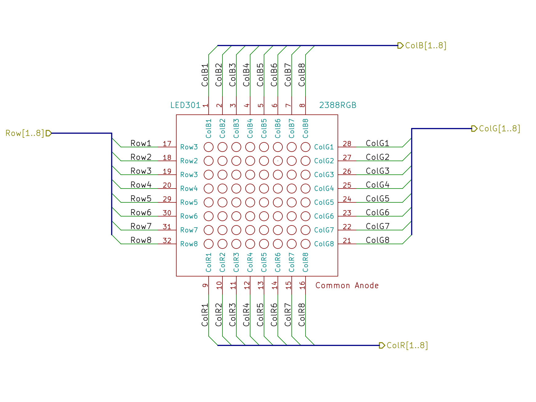
The LED panel has common-anode rows and separate RGB columns. This part layout makes it look far more symmetrical than it should be, but it’d be a page wide with all 24 column lines along the bottom, where they should be:
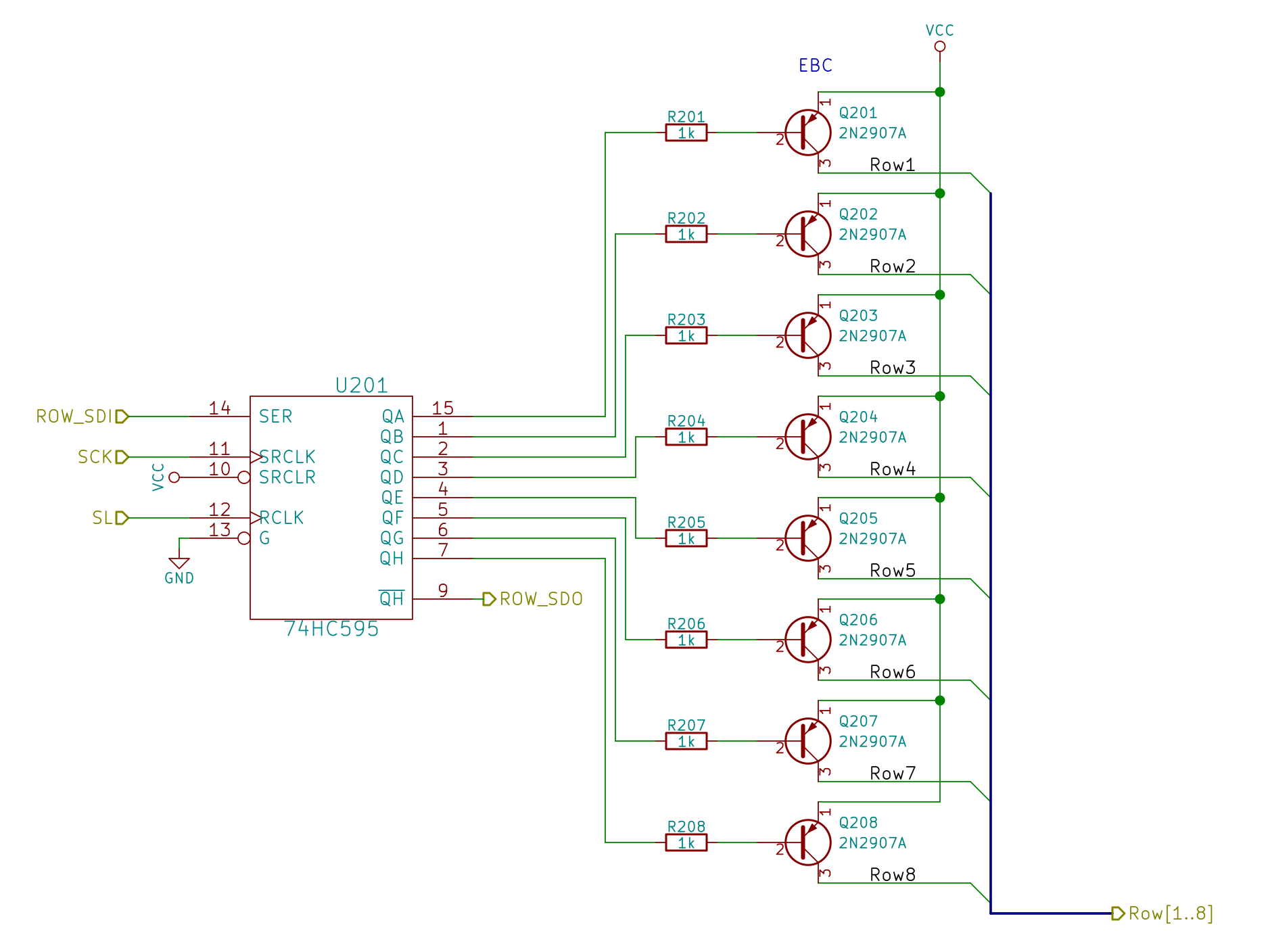
The row drivers use 2N2907A PNP transistors from my lifetime supply:
The column drivers abuse 74HC595 shift registers (because SPI) as current sinks:
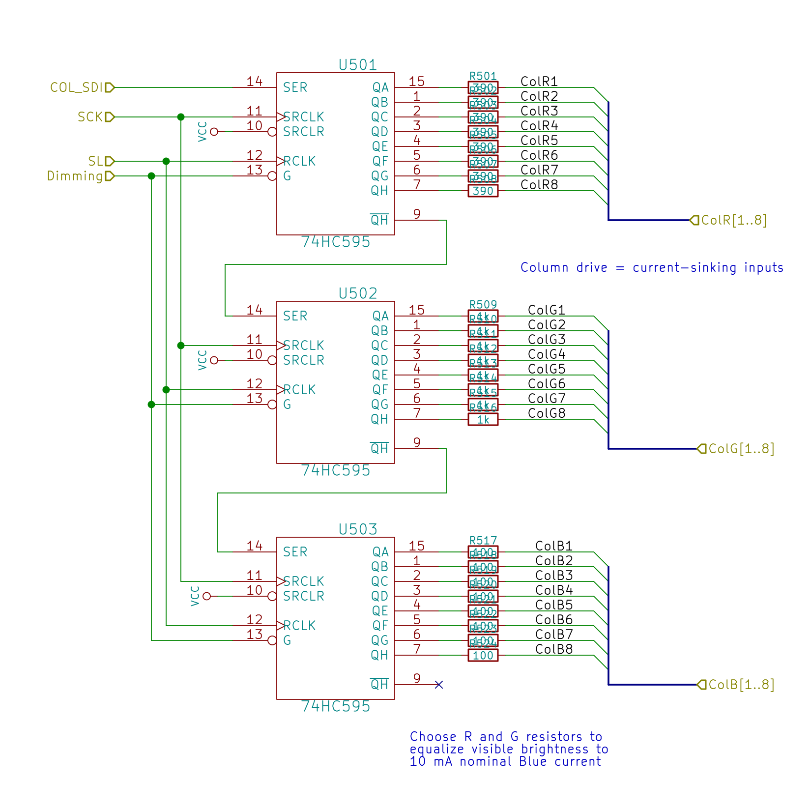
This thing will become a desk toy, so the LEDs need be only bright enough for direct viewing at short range. The panel (or some similar panel) can run at 50 mA continuous current, enough to put spots on your retinas, so throttling it back seemed prudent.
In any event, the shift registers can’t handle all that much current, so I set the blue LEDs at a nominal 10 mA and picked the other ballast resistors to produce more-or-less the same brightness. In round numbers, the red LEDs run at 5 mA and the green at 3 mA:

An all-on blue row will dump 80 mA (more or less) into a single 74HC595, which seems to be within its specs, and the registers for the other colors will loaf along at a few tens of mA. In real life, you’d use actual LED drivers, perhaps with PWM intensity control, and be done with it. Here, I’m going cheap and easy with eight colors, one of which is off.
The LED chips sit at the bottom of a white funnel (OK, a frustum) under a clear flat lens, with the red and blue chips washing the closest sides. All-on white sites (R+G+B, lower left) came out slightly blue overall, with a reddish tinge toward the top. Magenta sites (R+B, upper left) seem slightly more reddish than they should be. Cyan sites (G+B, middle right) have too little green.
The granularity of SMD resistor values in my heap limits the amount of fine tuning; I am so not going to stack SMD resistors for color adjustment.
None of that matters in this application, of course.

Comments
One response to “Random LED Dots: Circuitry”
[…] second post covers the circuit design, and is worth a look if you’re new to driving many LEDs from a minimum number of […]