The Smell of Molten Projects in the Morning

Ed Nisley's Blog: Shop notes, electronics, firmware, machinery, 3D printing, laser cuttery, and curiosities. Contents: 100% human thinking, 0% AI slop.

Category: Software

General-purpose computers doing something specific

  • Converting Day-of-Year to Month and Day-of-Month, Then Back Again

    I needed the conversions for a WWVB simulator, so it knows when to twiddle the leap-year and leap-second bits.

    The general notion is a table with the Day-of-Year values for the last day of each month. The most expedient way of doing this is with two columns: one for normal years and the other for leap years, thusly…

    Month EOM EOM-LY DOY DOY-LY
    0 0 0 0 0
    1 31 31 31 31
    2 28 29 59 60
    3 31 31 90 91
    4 30 30 120 121
    5 31 31 151 152
    6 30 30 181 182
    7 31 31 212 213
    8 31 31 243 244
    9 30 30 273 274
    10 31 31 304 305
    11 30 30 334 335
    12 31 31 365 366

    Hint: even if you can recite the “Thirty days hath November …” jingle, it’s much better to build a spreadsheet so the additions all work out. It’s even better if you don’t attempt any of this with a late-summer head cold. You might want to check all my work, because I’m still stuffy.

    With table in hand, the code is straightforward.

    Define a structure with all the various bits & pieces of the current time, much of which isn’t used here. It’s all needed in the WWVB simulator:

    enum EVENTSTATE {EVENT_INACTIVE,EVENT_PENDING,EVENT_ACTIVE};
    
    struct timecode_ {			// The current moment in time...
      byte Year;				// 0 - 99
      word DayOfYear;			// 1 - 366
      byte Hour;				// 0 - 23
      byte Minute;				// 0 - 59
      byte Second;				// 0 - 60 (yes!)
      byte Tenth;				// 0 - 9
      enum EVENTSTATE LeapYear;		// 0 = no, 1 = pending, 2 = active
      enum EVENTSTATE LeapSecond;		// 0 = no, 1 = pending, 2 = active in this minute
      enum EVENTSTATE DaylightSavingTime;	// 0 = no, 1 = pending, 2 = active
      char UT1Correction;			// 100 ms units, -10 to +10 range (+/- 1 second)
      byte MinuteLength;			// 60 or 61
      byte Month;				// 1 - 12 (not sent in frame)
      byte DayOfMonth;			// 1 - 28..31	(not sent in frame)
    };
    

    That’s obviously overspecified, because DayOfYear with LeapYear uniquely determines Month and DayOfMonth. It’s handy to have both forms around, sooo there they are.


    Then set up the table, glossing over the quick matrix transposition that turns the entries for each year into rows rather than columns:

    prog_uint16_t PROGMEM MonthEnds[2][13] = {
      0,31,59,90,120,151,181,212,243,273,304,334,365,
      0,31,60,91,121,152,182,213,244,274,305,335,366
    };
    

    Conversion from DayOfYear to Month and DayOfMonth requires searching backwards through the appropriate table row until you find the entry that’s smaller than the DayOfYear value, at which point you’ve found the right month.

    void ConvertDOYtoDOM(struct timecode_ *pTime) {
    byte Index,LY;
    word EndOfMonth;
      LY = (EVENT_INACTIVE != pTime->LeapYear) ? 1 : 0;
      Index = 12;
      while ((EndOfMonth = pgm_read_word(&MonthEnds[LY][Index])) >= pTime->DayOfYear) {
    	--Index;
      };
      pTime->Month = Index + 1;									// months start with 1, not 0
      pTime->DayOfMonth = (byte)(pTime->DayOfYear - EndOfMonth);
    }
    

    Converting from Month and DayOfMonth to DayOfYear is much easier, as it’s pretty much just a table lookup:

    word ConvertDOMtoDOY(struct timecode_ *pTime) {
    word EndOfMonth;
      EndOfMonth = pgm_read_word(&MonthEnds[(EVENT_INACTIVE != pTime->LeapYear) ? 1 : 0][pTime->Month - 1]);
      return EndOfMonth + pTime->DayOfMonth;
    }
    

    This code might actually work, but if I were you, I’d test it pretty thoroughly before lashing it into your project…


    The PROGMEM and pgm_read_word() stuff is the Arduino mechanism that puts the lookup table into Flash program memory rather than the ATMega168’s exceedingly limited RAM space. The definitive word about that process resides there.

    Memo to Self: Using const simply makes the variable kinda-sorta read-only, but still initializes RAM from Flash. The PROGMEM routines delete the RAM copy entirely.

  • Arduino: Be Careful With the Preprocessor

    This trips me up every damn time…

    Although the Arduino language looks like C and parses like C and runs like C, it’s not really C. It’s a specialized language gnawed on by a vast conversion monster and eventually shat out as executable ATmega-style instructions.

    Here’s a (rather contrived) trivial working program…

    #define PIN_ARDUINOLED    13     // standard LED
    
    typedef struct {
     int initial;
     int on;
     int off;
     int reps;
    } timeout_ ;
    
    timeout_ Trial = {2000,100,1000,5};
    
    void setup() {
     pinMode(PIN_ARDUINOLED,OUTPUT);
    }
    
    void loop() {
    
    int counter;
    
     digitalWrite(PIN_ARDUINOLED,LOW);
     delay(Trial.initial);
    
     for (counter = 0; counter < Trial.reps; ++counter) {
     digitalWrite(PIN_ARDUINOLED,HIGH);
     delay(Trial.on);
     digitalWrite(PIN_ARDUINOLED,LOW);
     delay(Trial.off);
     }
    
    }

    That compiles and runs just like you’d expect: a long delay, followed by five blinks, repeating endlessly.

    Now, use some preprocessor conditionals to gut-and-replace the code, with a bit of garish colorization to make things more obvious. This is Bad Programming Practice, but work with me…

    #define PIN_ARDUINOLED    13        // standard LED
    
    #if 0
    typedef struct {
     int initial;
     int on;
     int off;
     int reps;
    } timeout_ ;
    #endif
    
    #if 0
    timeout_ Trial = {2000,100,1000,5};
    #else
    int LoopCount = 50;
    #endif
    
    void setup() {
     pinMode(PIN_ARDUINOLED,OUTPUT);
    }
    
    void loop() {
    
    int counter;
    
    #if 0
     digitalWrite(PIN_ARDUINOLED,LOW);
     delay(Trial.initial);
    
     for (counter = 0; counter < Trial.reps; ++counter) {
     digitalWrite(PIN_ARDUINOLED,HIGH);
     delay(Trial.on);
     digitalWrite(PIN_ARDUINOLED,LOW);
     delay(Trial.off);
     }
    #else
     digitalWrite(PIN_ARDUINOLED,LOW);
     for (counter = 0; counter < LoopCount; ++counter) {
     digitalWrite(PIN_ARDUINOLED,HIGH);
     delay(250);
     digitalWrite(PIN_ARDUINOLED,LOW);
     delay(500);
     }
    
    #endif
    
    }

    The error message lump resulting from compiling that looks like:

    In function ‘void setup()’:
    error: ‘OUTPUT’ was not declared in this scope In function ‘void loop()’:
     In function ‘int main()’:

    Really?

    Delete the lines already removed by the preprocessor, the lines that shouldn’t be there when the code reaches the compiler, and you have:

    #define PIN_ARDUINOLED        13              // standard LED
    
    int LoopCount = 50;
    
    void setup() {
     pinMode(PIN_ARDUINOLED,OUTPUT);
    }
    
    void loop() {
    
    int counter;
    
     digitalWrite(PIN_ARDUINOLED,LOW);
     for (counter = 0; counter < LoopCount; ++counter) {
     digitalWrite(PIN_ARDUINOLED,HIGH);
     delay(250);
     digitalWrite(PIN_ARDUINOLED,LOW);
     delay(500);
     }
    
    }

    Which compiles and runs like a champ, of course. It blinks merrily away, more off than on, forever. The LoopCount variable doesn’t do much for us, but it’s the thought that counts.

    Put the original lines back, comment out the new stuff, and you get:

    #define PIN_ARDUINOLED        13              // standard LED
    
    typedef struct {
     int initial;
     int on;
     int off;
     int reps;
    } timeout_ ;
    
    timeout_ Trial = {2000,100,1000,5};
    
    #if 0
    int LoopCount = 50;
    #endif
    
    void setup() {
     pinMode(PIN_ARDUINOLED,OUTPUT);
    }
    
    void loop() {
    
    int counter;
    
     digitalWrite(PIN_ARDUINOLED,LOW);
     delay(Trial.initial);
    
     for (counter = 0; counter < Trial.reps; ++counter) {
     digitalWrite(PIN_ARDUINOLED,HIGH);
     delay(Trial.on);
     digitalWrite(PIN_ARDUINOLED,LOW);
     delay(Trial.off);
     }
    
    #if 0
     digitalWrite(PIN_ARDUINOLED,LOW);
     for (counter = 0; counter < LoopCount; ++counter) {
     digitalWrite(PIN_ARDUINOLED,HIGH);
     delay(250);
     digitalWrite(PIN_ARDUINOLED,LOW);
     delay(500);
     }
    
    #endif
    
    }

    And that compiles and runs perfectly, just like you’d expect. Uh-huh. Right.

    Basically, there’s a complex interaction between ordinary C preprocessor directives, ordinary C language elements, and the inscrutable innards of the Arduino IDE & compiler chain.

    As nearly as I can tell, you can wrap #if whatever around simple declarations and most executable code with impunity, but putting anything more elaborate than that, like a simple typedef struct, inside the conditionals causes bizarre problems.

    In fact, just typedef can cause problems, particularly if you attempt to use the ensuing tag in a function declaration. Don’t even think about anything along these lines:

    typedef struct {whatever} taggit_;
    ... snippage ...
    void SomeFunction(taggit_ *pThing) {
    ... snippage ...
    }

    However, this seems to work fine:

    struct taggit_ {whatever};
    ... snippage ...
    void SomeFunction(struct taggit_ *pThing) {
    ... snippage ...
    }

    Trying to make sense of this will drive you mad (well, it drives me mad), but when you get bizarre error messages that can’t be explained by the usual operator screwups, well, most likely you’re being too clever with the preprocessor.

    Or you’ve (also) made a trivial typo that cannot be discovered by inspection.

    It seems the right (only?) way to handle typedef definitions is to put ’em in a separate header file, as described there, then add the header file to your sketch in a separate tab. That seems to insert the definitions in the proper order within the *.cpp file that actually goes into the compiler.

    However, some limited fiddling reveals that I don’t understand the nuances or I’m screwing it up. Probably both.

    Memo to Self: define the structs & variables without typedefs, then prepare for some protracted tweakage…

  • Seiko Epson RTC-65271 Real Time Clock Datasheet

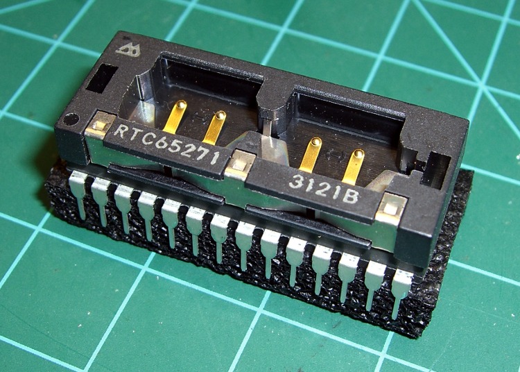
    RTC-65271 Module
    RTC-65271 Module

    I have a stash of RTC65271 real-time clock modules and might use one in an upcoming project. They’re obsolete by nigh onto two decades, but it’s a one-off project and I know I’ve been saving these things for some good reason.

    Alas, the datasheet doesn’t seem to appear anywhere else on the web; you can find an overview & general description, but not how the thing actually works.

    However, if you happen to have a chip and need the datasheet, this is indeed your lucky day: a scanned RTC65271 Datasheet.

    The datasheet alleges it’s “functionally compatible with MC146818A and DS1287“, and those datasheets may be more readable, if not exactly applicable. It seems to be (similar to) the clock chip used in the original PC/AT, if you recall those relics, and might actually use standard hardware & software protocols.

    Dealing with this thing may be more trouble than it’s worth in this day of bus-less microcontrollers with Serial Peripheral Interface widgetry. A back-of-the-envelope count says it’d require three ‘595 output chips and a ‘166 input chip to fit on an SPI bus. Yuch…

    Hey, if you want one, drop me a note. I have far more than a lifetime supply at my current rate of consumption.

  • TCFFHRC Rules Document: LyX / LaTeX Settings

    I’m editing the Trinity College Home Firefighting Robot Contest rules document using the LyX GUI front end to LaTeX to handle the formatting.

    Yes, yes, I know OpenOffice and its ilk have all the features you think you need. When you actually try to put together a book-length document, you find that the features don’t actually work / work together / behave reliably. Been there, done that. Enough times to be wary, indeed.

    So LyX / LaTeX is the least-worst alternative and actually does a pretty good job after you get the various configurations beaten into shape. After that, you just type, add tags, and it’s all good.

    Here’s a list of the settings I’m using… for future reference, natch, because figuring this stuff out from first principles takes a while.

    Document settings

    Document Class: report
    Text Layout: MedSkip vertical, Single line, Two-column
    Page Layout: US Letter, fancy headings
    Page Margins: 0.75 inch all around, 0.3 inch separations</pre>
    <strong>LaTeX Preamble</strong>
    <pre>\usepackage{ragged2e}
    \usepackage{lastpage}
    \usepackage{url}
    \usepackage{dvipost}
    \usepackage{breakurl}
    \usepackage[labelfont={bf,sf}]{caption}
    \renewcommand{\bottomfraction}{0.7}
    \pagestyle{fancyplain}
    \fancyhf{}
    \lhead{\fancyplain{}{Trinity College Home Robot Contests}}
    \rhead{\fancyplain{}{2010 Rules}}
    \lfoot{\fancyplain{Modified \today}{Modified \today}}
    \cfoot{Copyright 2009 by Trinity College}
    \rfoot{\fancyplain{\thepage\ of \pageref{LastPage}}{\thepage\ of \pageref{LastPage}}}
    \RaggedRight
    \dvipostlayout
    \dvipost{cbstart color push Blue}
    \dvipost{cbend color pop}
    

    Trickery


    Some of those packages aren’t part of the default LyX / LaTeX installation on Ubuntu. Searching for LaTeX in Synaptic is tedious, but works.

    The three ways to export to PDF are not identical.

    • dvipdfm doesn’t produce clickable TOC links.
    • pdflatex, the default, doesn’t produce change bars, which is a crippling defect for a rules document under heavy revision. It’s OK for the final draft, though.
    • ps2pdf doesn’t produce searchable text; it’s all graphics. Ptooie!

    So use dvipdfm during development (to get change bars) and use pdflatex for the final product (to get clickable links). There has got to be a way around that, but I haven’t a clue as to what’s going on under the hood.

    In order to track changes:

    Document -> Change Tracking -> Track Changes.

    In order to print change bars and suchlike:

    Document -> Change Tracking -> Show Changes in Output

    Figures appear on-screen in dot-for-dot mode by default, so tweak the on-screen ratio to maybe 50%. Force the printed width of all figures to 3 inches for two-column layout. Insist that picture resolution bear some resemblance to reality: 3 inches at 300 dpi -> 1000 pixels across.

    There seems to be no way to export LyX directly to ODT. Exporting to RTF strips off most of the formatting, as you’d expect, and change tracking Goes Away.

    Exporting to HTML produces one honkin’ big lump of HTML with a bazillion image files in a separate directory. That’s probably OK for most purposes.

    Memo to Self: Turn off change tracking for minor editorial tweakage, because nobody really cares.

  • Adding a Device to LTSpiceIV

    Searching around for an LM386 SPICE model turned up this useful thread.

    The model has some limitations, discussed there, but seems practical. So far, the main gotcha is that the output voltage doesn’t center neatly at Vcc/2, but that’s in the nature of fine tuning.

    The trick is getting the model & symbol into Linear Technology’s LTSpiceIV…

    Running under WINE in Xubuntu, the emulated C drive is in your home directory at

    .wine/drive_c/

    with the Linear Tech LTSpiceIV files tucked inside that at

    .wine/drive_c/Program\ Files/LTC/LTspiceIV/

    Incidentally, WINE puts the program icon in

    .local/share/icons/05f1_scad3.0.xpm

    It’s not clear what the prefix means, but the actual executable is scad3.exe (I think that’s historical cruft, as the new overall name is LTSpiceIV).

    Copy the LM386.sub file to lib/sub and the LM386.asy file to lib/sym, then restart LTSpiceIV.

    After putting the symbol in the schematic, I had to edit its attributes (other-click the symbol), make both InstName & Value visible to see them on the schematic, then move them to somewhere other than dead-center in the symbol. I can’t figure out how to make that happen automagically, as it does with other symbols. Comparing the two files to ordinary components doesn’t show anything obviously missing.

    Link rot being what it is, here’s the LM386.sub file:

    * lm386 subcircuit model follows:
    
    ************************************original* IC pins:     2   3   7   1   8   5   6   4
    * IC pins:     1   2   3   4   5   6   7   8
    *              |   |   |   |   |   |   |   |
    .subckt lm386 g1  inn inp gnd out  vs byp g8
    ************************************original*.subckt lm386 inn inp byp  g1  g8 out  vs gnd
    
    * input emitter-follower buffers:
    
    q1 gnd inn 10011 ddpnp
    r1 inn gnd 50k
    q2 gnd inp 10012 ddpnp
    r2 inp gnd 50k
    
    * differential input stage, gain-setting
    * resistors, and internal feedback resistor:
    
    q3 10013 10011 10008 ddpnp
    q4 10014 10012 g1 ddpnp
    r3 vs byp 15k
    r4 byp 10008 15k
    r5 10008 g8 150
    r6 g8 g1 1.35k
    r7 g1 out 15k
    
    * input stage current mirror:
    
    q5 10013 10013 gnd ddnpn
    q6 10014 10013 gnd ddnpn
    
    * voltage gain stage & rolloff cap:
    
    q7 10017 10014 gnd ddnpn
    c1 10014 10017 15pf
    
    * current mirror source for gain stage:
    
    i1 10002 vs dc 5m
    q8 10004 10002 vs ddpnp
    q9 10002 10002 vs ddpnp
    
    * Sziklai-connected push-pull output stage:
    
    q10 10018 10017 out ddpnp
    q11 10004 10004 10009 ddnpn 100
    q12 10009 10009 10017 ddnpn 100
    q13 vs 10004 out ddnpn 100
    q14 out 10018 gnd ddnpn 100
    
    * generic transistor models generated
    * with MicroSim's PARTs utility, using
    * default parameters except Bf:
    
    .model ddnpn NPN(Is=10f Xti=3 Eg=1.11 Vaf=100
    + Bf=400 Ise=0 Ne=1.5 Ikf=0 Nk=.5 Xtb=1.5 Var=100
    + Br=1 Isc=0 Nc=2 Ikr=0 Rc=0 Cjc=2p Mjc=.3333
    + Vjc=.75 Fc=.5 Cje=5p Mje=.3333 Vje=.75 Tr=10n
    + Tf=1n Itf=1 Xtf=0 Vtf=10)
    
    .model ddpnp PNP(Is=10f Xti=3 Eg=1.11 Vaf=100
    + Bf=200 Ise=0 Ne=1.5 Ikf=0 Nk=.5 Xtb=1.5 Var=100
    + Br=1 Isc=0 Nc=2 Ikr=0 Rc=0 Cjc=2p Mjc=.3333
    + Vjc=.75 Fc=.5 Cje=5p Mje=.3333 Vje=.75 Tr=10n
    + Tf=1n Itf=1 Xtf=0 Vtf=10)
    
    .ends
    *----------end of subcircuit model-----------

    And the corresponding LM386.asy file:

    Version 4
    SymbolType CELL
    LINE Normal -64 -63 64 0
    LINE Normal -64 65 64 0
    LINE Normal -64 -63 -64 65
    LINE Normal -60 -48 -52 -48
    LINE Normal -60 48 -52 48
    LINE Normal -56 52 -56 44
    LINE Normal -48 -80 -48 -55
    LINE Normal -48 80 -48 57
    LINE Normal -44 -68 -36 -68
    LINE Normal -40 -72 -40 -64
    LINE Normal -44 68 -36 68
    LINE Normal -16 -39 -16 -64
    LINE Normal 0 32 0 48
    LINE Normal 48 -8 48 -32
    SYMATTR Value LM386
    SYMATTR Prefix X
    SYMATTR ModelFile LM386.sub
    SYMATTR Value2 LM386
    SYMATTR Description Low power audio amplifier
    PIN -16 -64 LEFT 8
    PINATTR PinName g1
    PINATTR SpiceOrder 1
    PIN -64 -48 NONE 0
    PINATTR PinName In-
    PINATTR SpiceOrder 2
    PIN -64 48 NONE 0
    PINATTR PinName In+
    PINATTR SpiceOrder 3
    PIN -48 80 NONE 0
    PINATTR PinName V-
    PINATTR SpiceOrder 4
    PIN 64 0 NONE 0
    PINATTR PinName OUT
    PINATTR SpiceOrder 5
    PIN -48 -80 NONE 0
    PINATTR PinName V+
    PINATTR SpiceOrder 6
    PIN 0 48 LEFT 8
    PINATTR PinName bp
    PINATTR SpiceOrder 7
    PIN 48 -32 LEFT 8
    PINATTR PinName g8
    PINATTR SpiceOrder 8

    Props to Roff, who actually created those files…

  • Wine: Adding Runtime Libraries

    While trying to persuade a Windows program to run under Wine, I stumbled across this useful script: winetricks.

    Basically, it downloads & installs the myriad runtime libraries / DLLs / programs that Windows programs generally assume are installed. Those are the things you don’t know are missing and generally can’t figure out how to install on your own.

    It didn’t actually help get the program in question running. As nearly as I can tell, if at first you can’t get a program installed & running under Wine, just give up…

  • Tucking Other Files into an OpenDocument Document

    WordPress doesn’t allow ZIP files, but very often I want to upload a collection of files that all relate to a common topic. For example, the three Tek 492 EPROM HEX files ought to come with a bit of documentation about how to use them.

    Fortunately, OpenDocument documents (sounds like something put out by the Department of Redundancy Department) are actually ordinary ZIP files with a different extension. There’s no good reason you can’t tuck some additional files into that container. Nay, verily, if you use a word processor file, then you can have documentation accompany your files!

    Note that the additional files don’t have any effect on the word processor document: OpenOffice simply uses the files it knows about and ignores the additional ones. You won’t see them in the word processor document; you won’t even know they’re present.

    However, because OpenOffice doesn’t know about them, it won’t transfer them to the new document when you save the file. You must add the files as the last step, after editing and saving the word processor document for the last time.

    I suppose there are pathological cases where this will cause trouble and I certainly hope that OpenDocument validators will complain vehemently about the presence of additional files. Use this knowledge wisely, OK?

    So, for example…

    Create a document and save it as the default ODT format using OpenOffice; let’s call it Tek 492 ROM Images.odt, just so you can see one in action.

    Now, to add those HEX files to it, you’d use the ordinary ZIP utility:

    zip "Tek 492 ROM Images.odt" *hex

    The quotes protect the blanks in the file name and you must type the entire file name out with the extension, because ZIP doesn’t expect to work with ODT files.

    You can list the file’s contents, which will show you all the other files that go into making an OpenDocument document work:

    unzip -l "Tek 492 ROM Images.odt"
    Archive:  Tek 492 ROM Images.odt
    Length     Date   Time    Name
    --------    ----   ----    ----
    39  07-30-09 18:09   mimetype
    0  07-30-09 18:09   Configurations2/statusbar/
    0  07-30-09 18:09   Configurations2/accelerator/current.xml
    0  07-30-09 18:09   Configurations2/floater/
    0  07-30-09 18:09   Configurations2/popupmenu/
    0  07-30-09 18:09   Configurations2/progressbar/
    0  07-30-09 18:09   Configurations2/menubar/
    0  07-30-09 18:09   Configurations2/toolbar/
    0  07-30-09 18:09   Configurations2/images/Bitmaps/
    23156  07-30-09 18:09   content.xml
    18259  07-30-09 18:09   styles.xml
    1240  07-30-09 18:09   meta.xml
    4943  07-30-09 18:09   Thumbnails/thumbnail.png
    8742  07-30-09 18:09   settings.xml
    1889  07-30-09 18:09   META-INF/manifest.xml
    4876  07-30-09 11:56   U1012 - 160-0886-04.hex
    19468  07-30-09 11:56   U2023 - 160-0838-00.hex
    19468  07-30-09 11:56   U2028 - 160-0839-00.hex
    --------                   -------
    102080                   18 files

    For obvious reasons, if you’re stuffing a bunch of files into an ODT file, you should probably ZIP them into a single ZIP file of their own, then add that single file to the ODT file. That means your victims users must also apply UNZIP twice, which may be expecting too much.

    When you want to use the HEX files, extract them:

    unzip "Tek 492 ROM Images.odt" *hex

    And there they are again:

    ls -l
    -rw-r--r-- 1 ed ed 15447 2009-08-11 20:51 Tek 492 ROM Images.odt
    -rw-r--r-- 1 ed ed  4876 2009-07-30 11:56 U1012 - 160-0886-04.hex
    -rw-r--r-- 1 ed ed 19468 2009-07-30 11:56 U2023 - 160-0838-00.hex
    -rw-r--r-- 1 ed ed 19468 2009-07-30 11:56 U2028 - 160-0839-00.hex

    That’s all there is to it…

    For what it’s worth, Microsoft DOCX files (and their ilk) are also ZIP files in disguise, so this same hack should work there, too. However, many folks (myself included) treat MS DOC files with the same casual nonchalonce as they do any other hunk of high-level radioactive waste, so stashing an additional payload in those files might not have a happy ending.

    This trick will certainly come in handy again, so I better write it down…