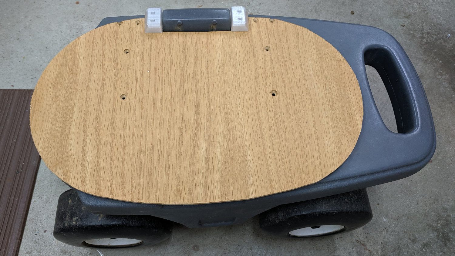
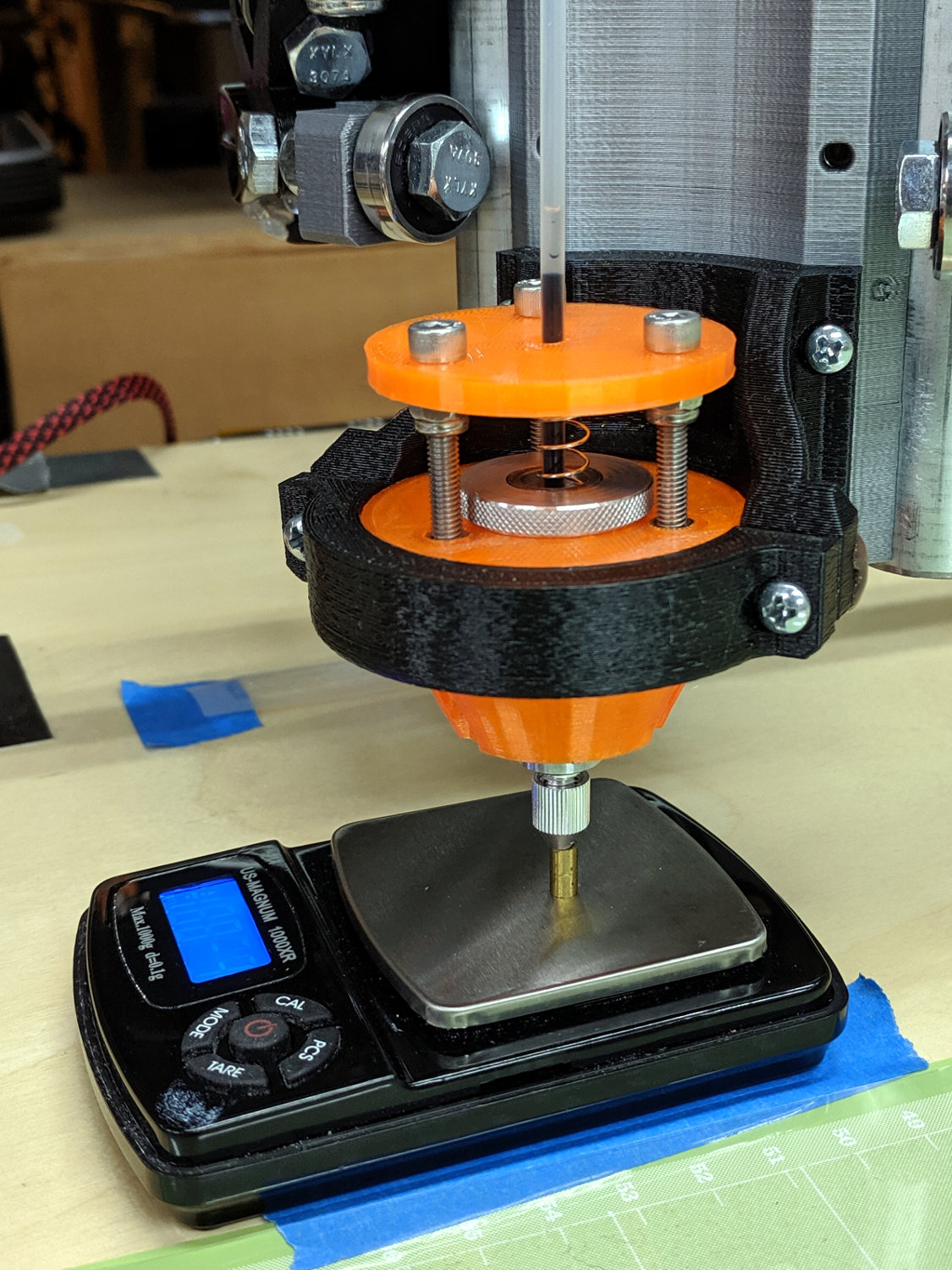
After nigh onto 18 years, the pipe straps holding the Zzipper fairing struts to the handlebars of our Tour Easy recumbents finally shrugged off their plastic wraps:

Although they still worked, riding over broken pavement produced distinct rattles; alas, the roads around here feature plenty of broken pavement.
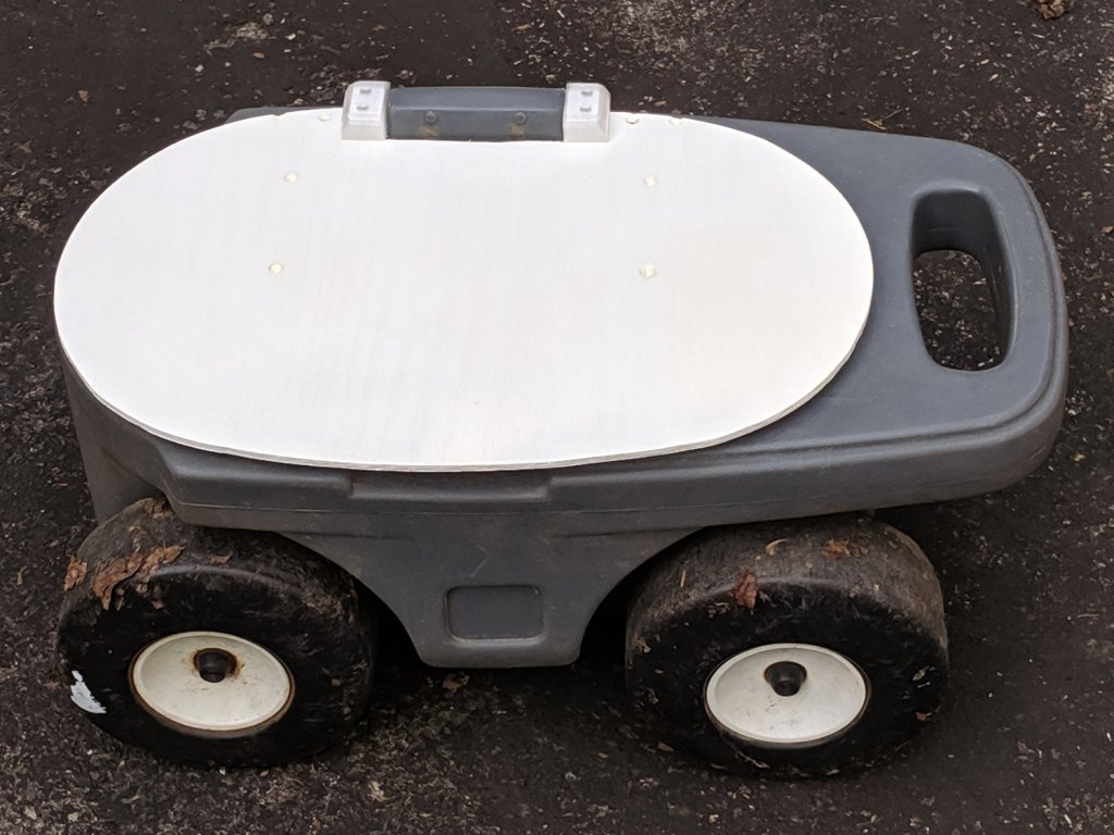
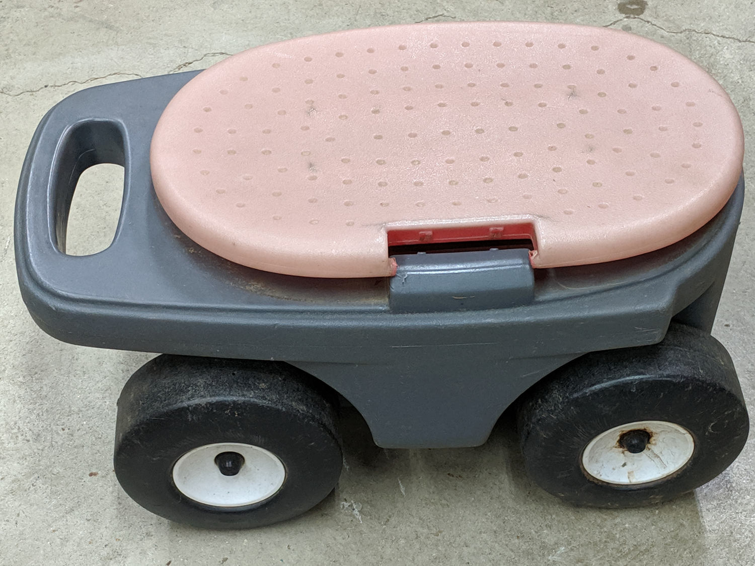
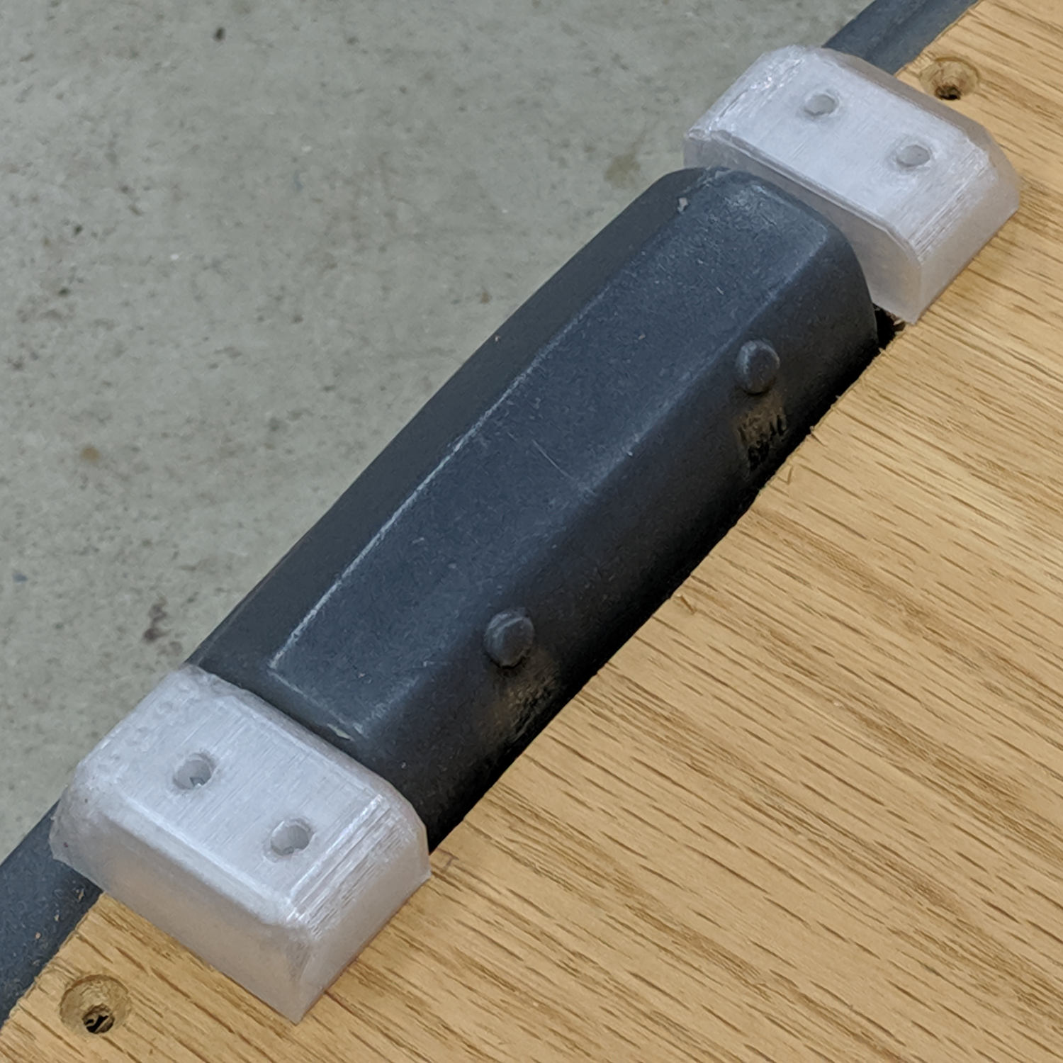
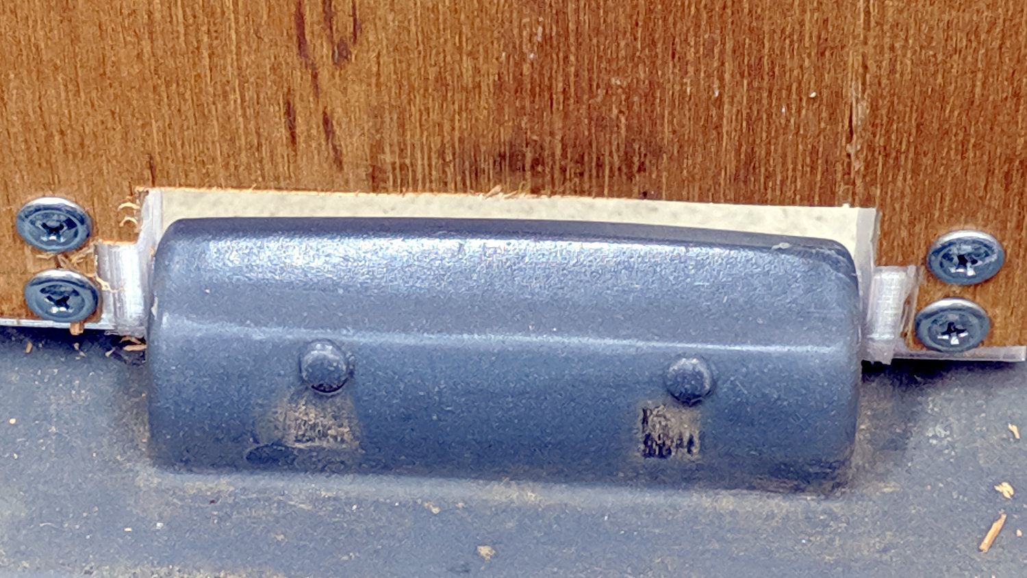
The solution is a rugged plastic block capped with aluminum plates to spread the clamping load:

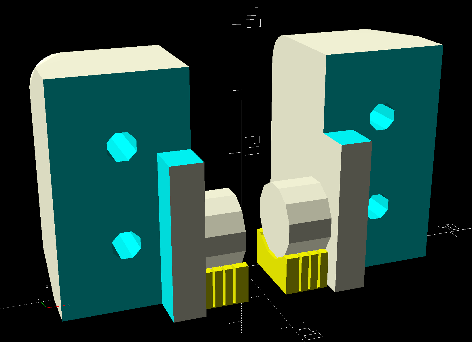
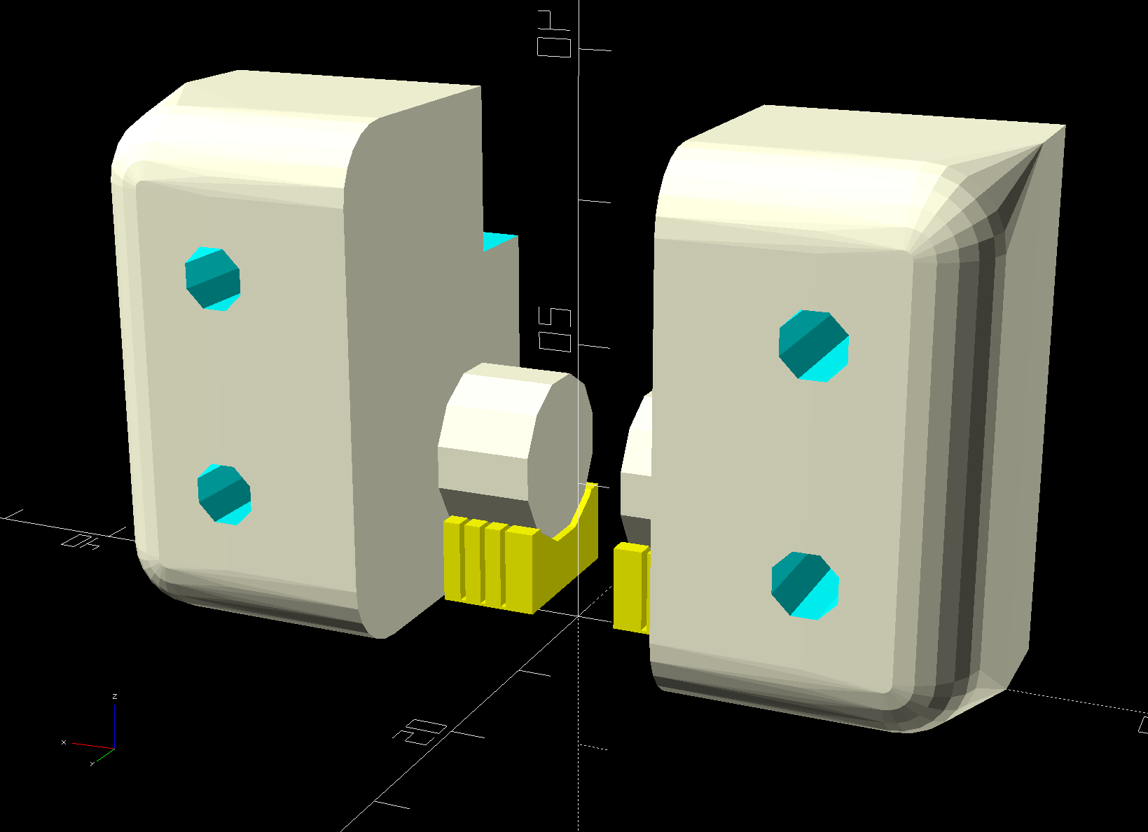
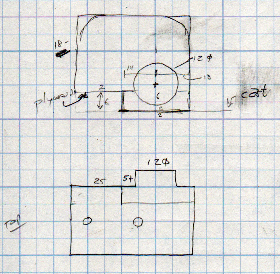
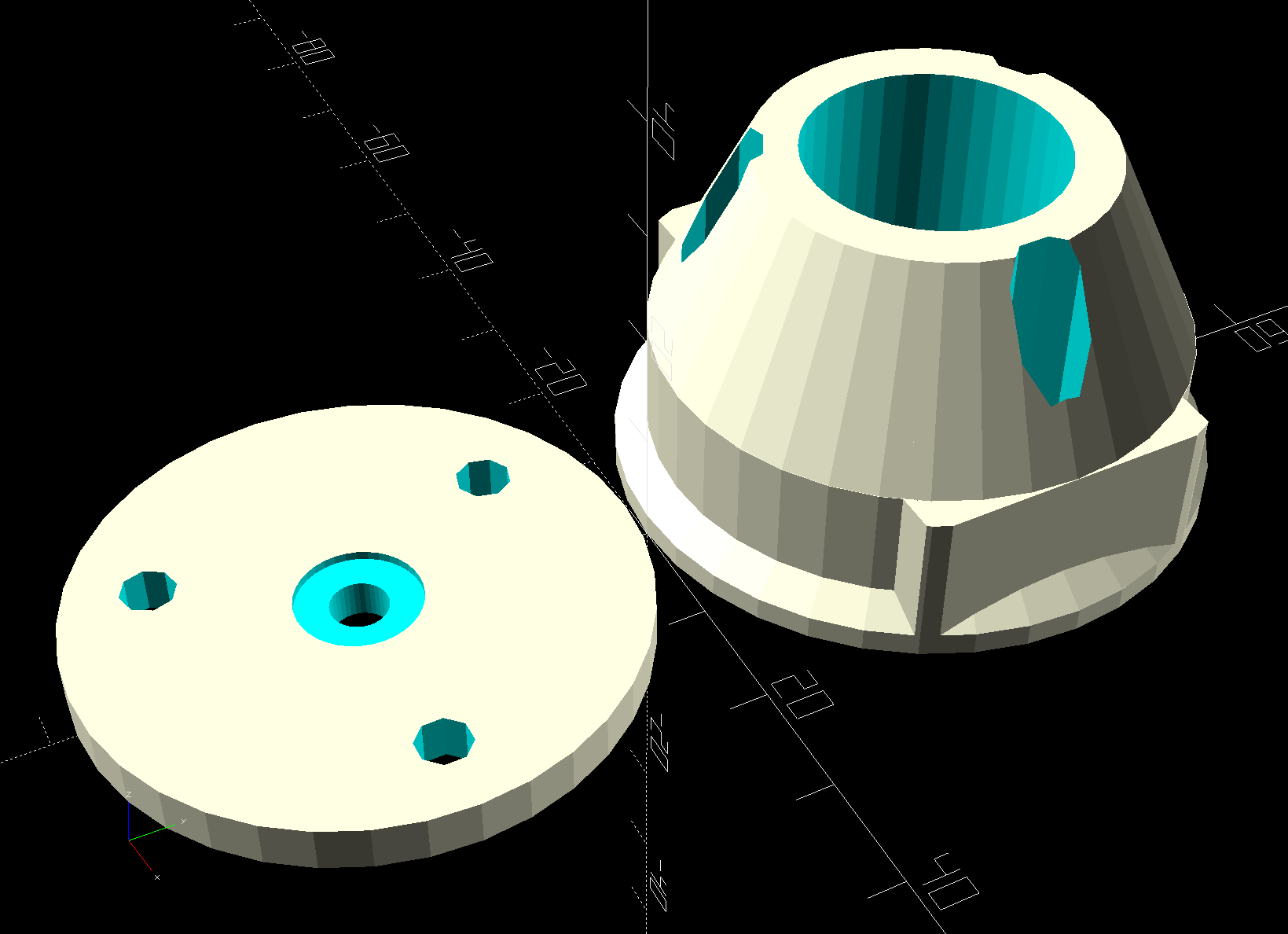
The solid model is straightforward:

A slight bit of tinkering made the stack exactly the right height for 45 mm screws secured with nyloc nuts. No washers on either end, although that’s definitely in the nature of fine tuning.
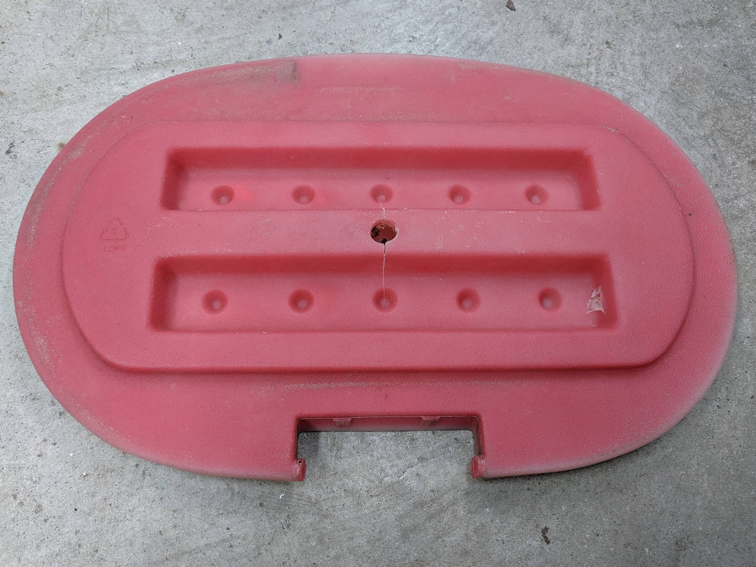
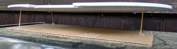
The three sections print without support:

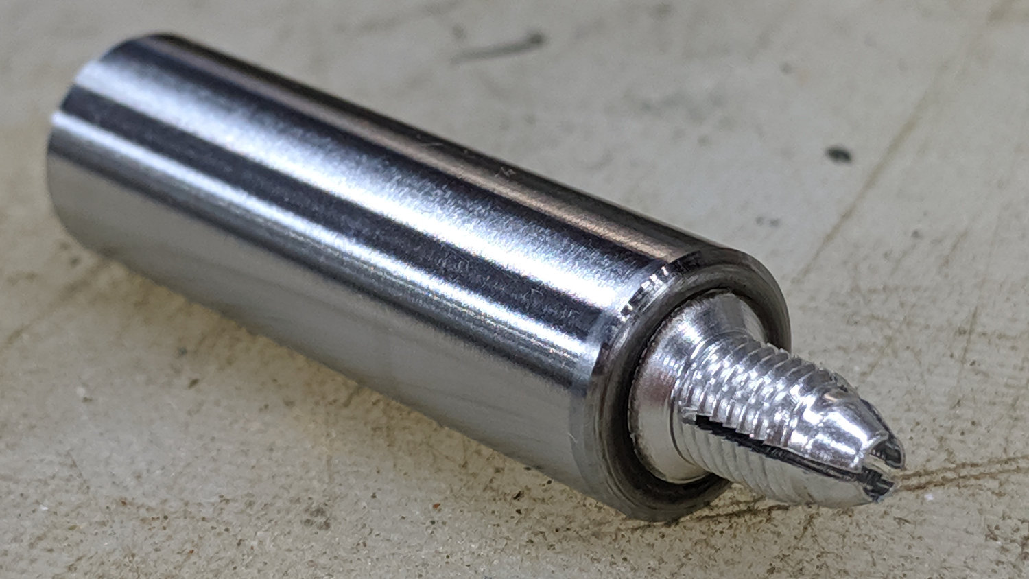
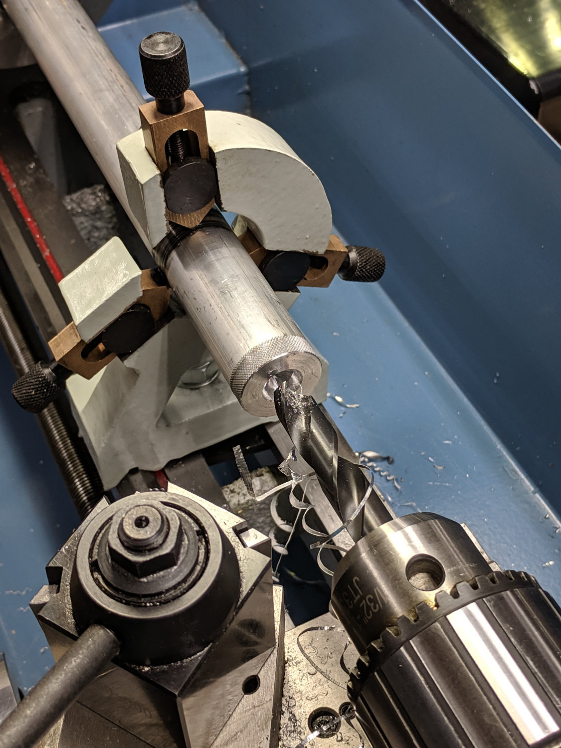
I reamed the smaller hole with a 3/8 inch drill to match the fairing strut rod. The as-printed larger hole fit the handlebar perfectly, although the first picture shows the tubing isn’t exactly round on the near side of the block, where it starts the outward bend toward the grips.
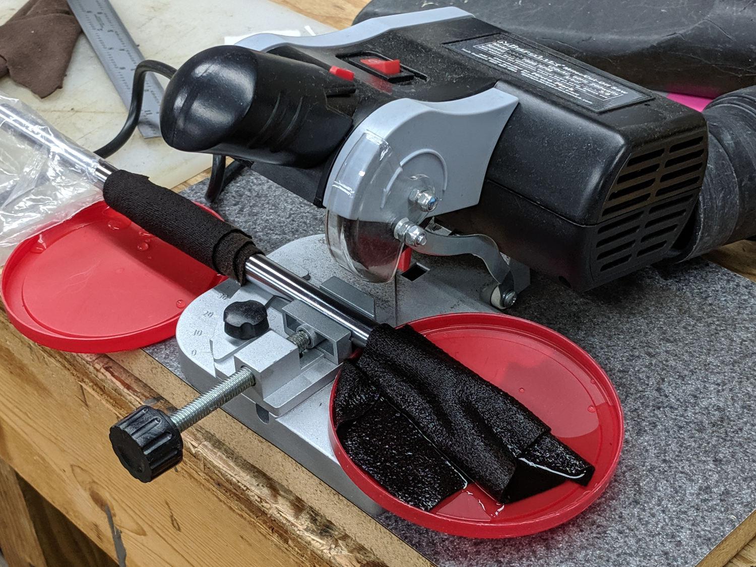
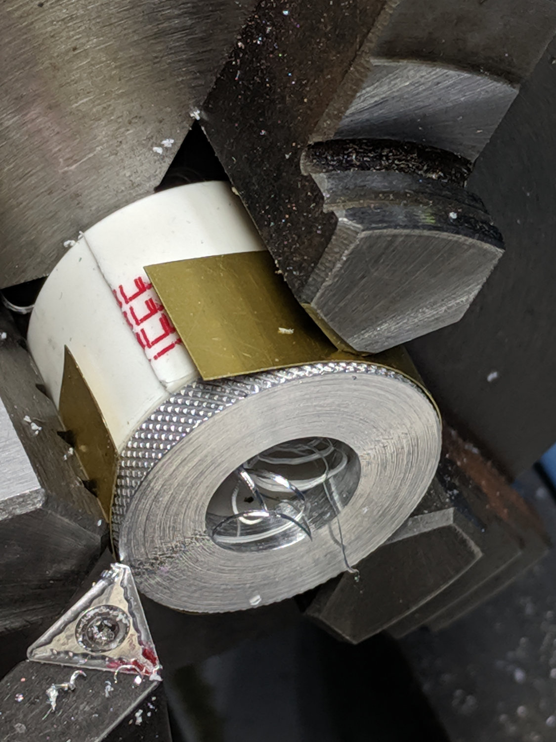
The cap plates cried out for CNC, but I simply traced two outlines of the block on 1/8 inch aluminum sheet, bandsawed near the line, introduced them to Mr Disk Sander for finishing & corner rounding, transfer-punched the holes from the plastic blocks, and drilled to suit:

Making two pairs of plates by hand counts as Quality Shop Time around here.
The first few rides confirm the fix: no rattles!
The OpenSCAD source code as a GitHub Gist:
| // Fairing strut mount for Tour Easy handlebars | |
| // Ed Nisley – KE4ZNU – 2019-08 | |
| Layout = "Show"; // [Show,Build,Block] | |
| Support = false; | |
| /* [Hidden] */ | |
| ThreadThick = 0.20; | |
| ThreadWidth = 0.40; | |
| HoleWindage = 0.2; | |
| Protrusion = 0.1; // make holes end cleanly | |
| function IntegerMultiple(Size,Unit) = Unit * ceil(Size / Unit); | |
| ID = 0; | |
| OD = 1; | |
| LENGTH = 2; | |
| inch = 25.4; | |
| //———————- | |
| // Dimensions | |
| // Handlebar along X axis, strut along Y, Z=0 at handlebar centerline | |
| HandlebarOD = 0.875 * inch + HoleWindage; | |
| StrutOD = 0.375 * inch + HoleWindage; | |
| PlateThick = 1.0 / 16.0 * inch; | |
| WallThick = 2.0; | |
| Screw = [3.0,6.8,4.0]; // M3 OD=washer, length=nut + washers | |
| RoundRadius = IntegerMultiple(Screw[OD]/2,0.5); // corner rounding | |
| ScrewOC = [IntegerMultiple(StrutOD + 2*WallThick + Screw[ID],0.5), | |
| IntegerMultiple(HandlebarOD + 2*WallThick + Screw[ID],0.5)]; | |
| echo(str("Screw OC: ",ScrewOC)); | |
| BlockSize = [ScrewOC.x + 2*RoundRadius,ScrewOC.y + 2*RoundRadius,HandlebarOD + StrutOD + 3*WallThick]; | |
| echo(str("Block: ",BlockSize)); | |
| HandleBarOffset = WallThick + HandlebarOD/2; // block bottom to centerline | |
| StrutOffset = HandlebarOD/2 + WallThick + StrutOD/2; // handlebar centerline to strut centerline | |
| echo(str("Screw length: ",BlockSize.z + 2*PlateThick + Screw[LENGTH])); | |
| NumSides = 2*3*4; | |
| //———————- | |
| // Useful routines | |
| module PolyCyl(Dia,Height,ForceSides=0) { // based on nophead's polyholes | |
| Sides = (ForceSides != 0) ? ForceSides : (ceil(Dia) + 2); | |
| FixDia = Dia / cos(180/Sides); | |
| cylinder(r=(FixDia + HoleWindage)/2, | |
| h=Height, | |
| $fn=Sides); | |
| } | |
| // Basic shapes | |
| // Block with handlebar along X axis | |
| module Block() { | |
| difference() { | |
| hull() | |
| for (i=[-1,1], j=[-1,1]) | |
| translate([i*ScrewOC.x/2,j*ScrewOC.y/2,-HandleBarOffset]) | |
| cylinder(r=RoundRadius,h=BlockSize.z,$fn=NumSides); | |
| for (i=[-1,1], j=[-1,1]) | |
| translate([i*ScrewOC.x/2,j*ScrewOC.y/2,-(HandleBarOffset + Protrusion)]) | |
| PolyCyl(Screw[ID],BlockSize.z + 2*Protrusion,8); | |
| translate([-BlockSize.x,0,0]) | |
| rotate([0,90,0]) | |
| cylinder(d=HandlebarOD,h=2*BlockSize.x,$fn=NumSides); | |
| translate([0,BlockSize.y,StrutOffset]) | |
| rotate([90,0,0]) | |
| cylinder(d=StrutOD,h=2*BlockSize.y,$fn=NumSides); | |
| } | |
| if (Support) { // totally ad-hoc | |
| color("Yellow") | |
| cube(1,center=true); | |
| } | |
| } | |
| //- Build it | |
| if (Layout == "Block") | |
| Block(); | |
| if (Layout == "Show") { | |
| Block(); | |
| color("Green",0.25) | |
| translate([-BlockSize.x,0,0]) | |
| rotate([0,90,0]) | |
| cylinder(d=HandlebarOD,h=2*BlockSize.x,$fn=NumSides); | |
| color("Green",0.25) | |
| translate([0,BlockSize.y,StrutOffset]) | |
| rotate([90,0,0]) | |
| cylinder(d=StrutOD,h=2*BlockSize.y,$fn=NumSides); | |
| } | |
| if (Layout == "Build") { | |
| translate([-1.2*BlockSize.x,0,HandleBarOffset]) | |
| difference() { | |
| Block(); | |
| translate([0,0,BlockSize.z]) | |
| cube(2*BlockSize,center=true); | |
| } | |
| translate([1.2*BlockSize.x,0,StrutOD/2 + WallThick]) | |
| difference() { | |
| rotate([180,0,0]) | |
| translate([0,0,-StrutOffset]) | |
| Block(); | |
| translate([0,0,BlockSize.z]) | |
| cube(2*BlockSize,center=true); | |
| } | |
| translate([0,0,StrutOffset]) | |
| rotate([180,0,0]) | |
| intersection() { | |
| Block(); | |
| translate([0,0,StrutOffset/2]) | |
| cube([2*BlockSize.x,2*BlockSize.y,StrutOffset],center=true); | |
| } | |
| } |