The Sandisk Extreme Pro 64 GB MicroSD card in the Sony HDR-AS30V died on the road once more, got reformatted, worked OK for a while, then kicked out catastrophic I/O errors after being mounted, so I swapped in the High Endurance card:
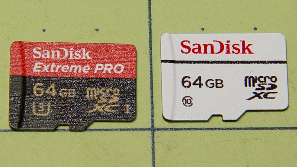
The Extreme Pro still passes the f3probe tests, so it’s not completely dead, but if I can’t trust it in the helmet camera, it’s dead to me.
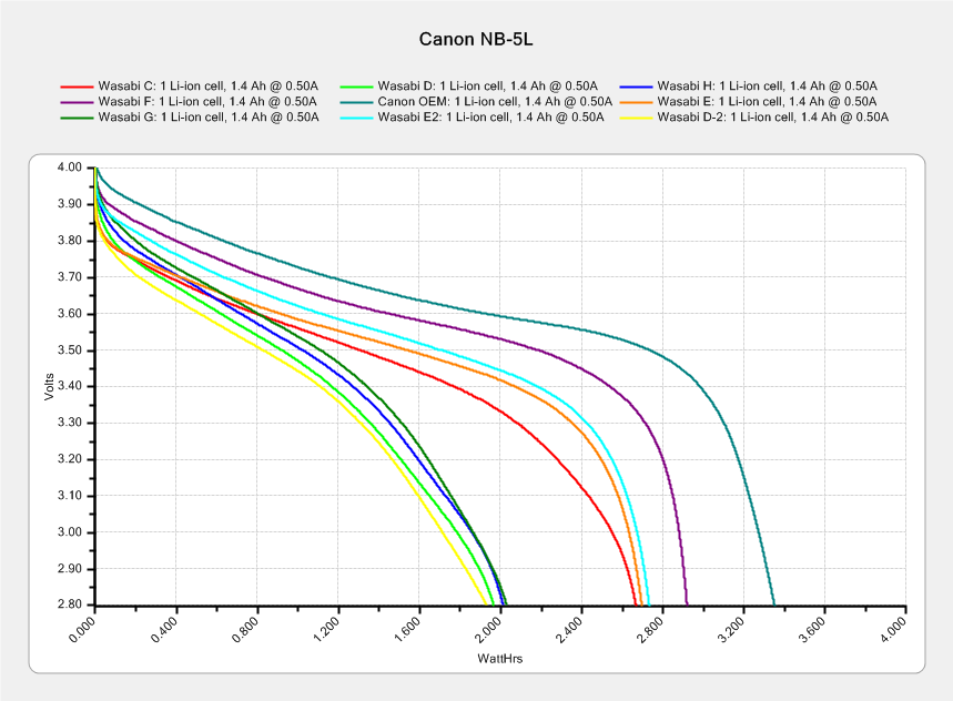
It survived 17 months of more-or-less continuous use, although we didn’t do nearly enough riding for three months early this year. Call it 14 months x five rides / week x 1 hour / ride = 300 hours of recording. Multiply by 4 GB / 22.75 minutes to get 3 TB of video, about 50 times its total capacity.
The never-sufficiently-to-be-damned Sony cards failed after less than 1 TB and 15-ish times capacity, making the Sandisk Extreme Pro much better. However, it’s painfully obvious these cards work better for low-intensity still-image recording, rather than continuous HD video.
Using them as Raspberry Pi “hard drives” surely falls somewhere between still cameras and video, although Octoprint’s video snapshots and streaming media must make ’em sweat.
We’ll see how Sandisk’s High Endurance memory works in precisely the application it’s labeled for.