Ed Nisley's Blog: Shop notes, electronics, firmware, machinery, 3D printing, laser cuttery, and curiosities. Contents: 100% human thinking, 0% AI slop.
I carry the Canon SX230HS in my pocket, so as to have a decent camera ready when it’s needed; yes, it’s in a cloth case. Unfortunately, in recent weeks a tiny hair made its way into the lens stack, where it shows up as a slight blurring just left of center in high f/stop images:
Cheap cartridge heater insulation
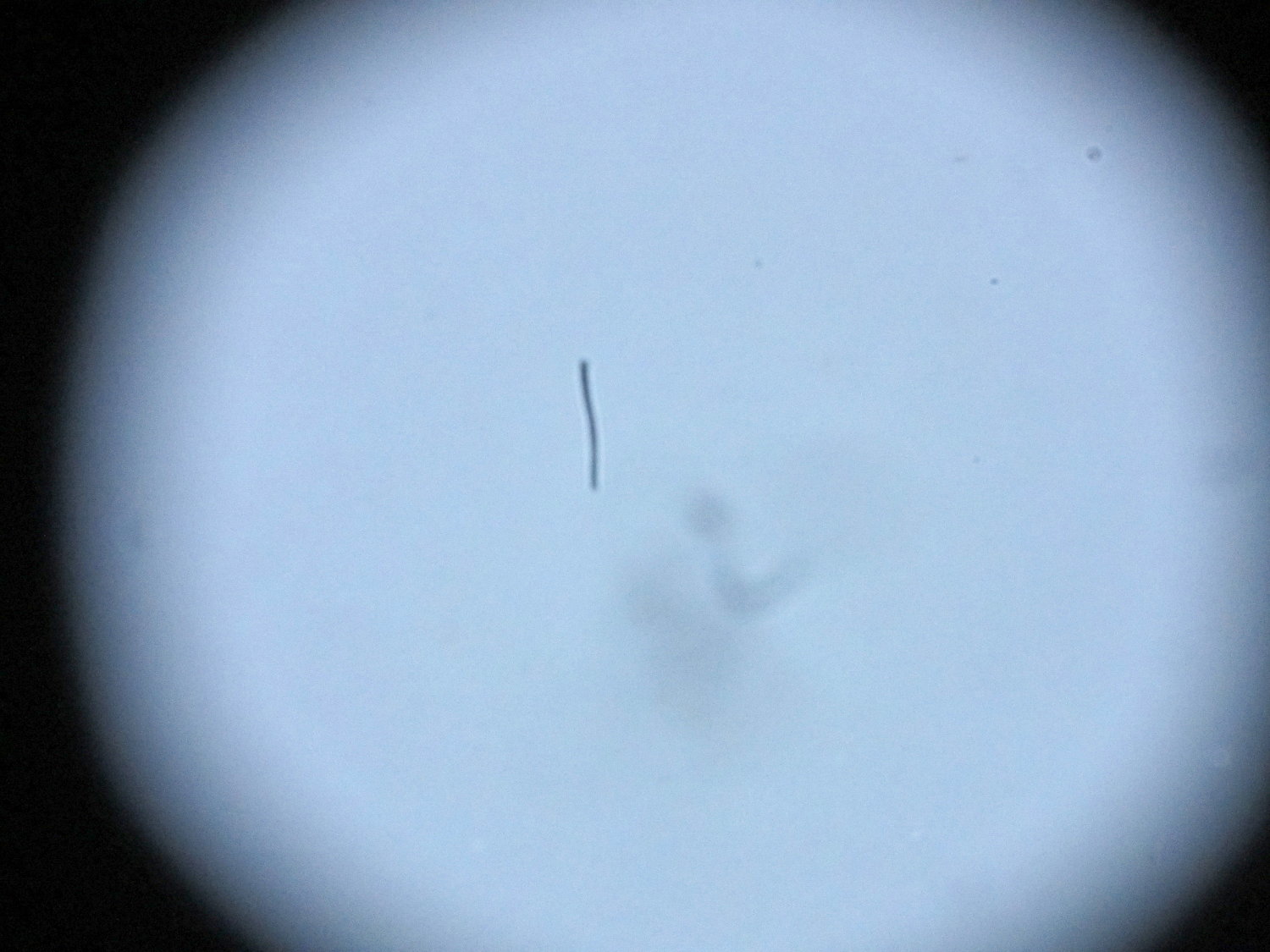
With the camera attached to the stereo zoom microscope, the hair becomes painfully obvious:
Hair on SX230HX Sensor
Of course it’s in the middle of the image. [sigh]
A bit of searching turns up a bootleg technique to remove the front lens from the turret (basically, just twist and pull), but neither of the internal lens surfaces thus revealed lie near a focal plane and, in any event, were surprisingly clean. The hair is probably lodged just in front of the image sensor, most likely stuck to the back of the final lens where it casts a shadow on the sensor. If it wandered around you’d call it a floater.
Dismantling the entire camera and opening the lens stack seems fraught with peril, particularly as the camera pretty much still works fine for normal picture-taking. More pondering is in order…
Part of the Curvelicious Cookie Cutter effort involved making the thinnest possible cutter blade wall consisting of two adjacent threads, because that’s about what the Afinia printer was producing (from a different model). My OpenSCAD code, based on an Inkscape model derived from the as-printed Afinia cutter, enlarges the cookie shape by a specific distance with a Minkowski sum; the model ultimately becomes G-Code directing the extruder nozzle around the outline.
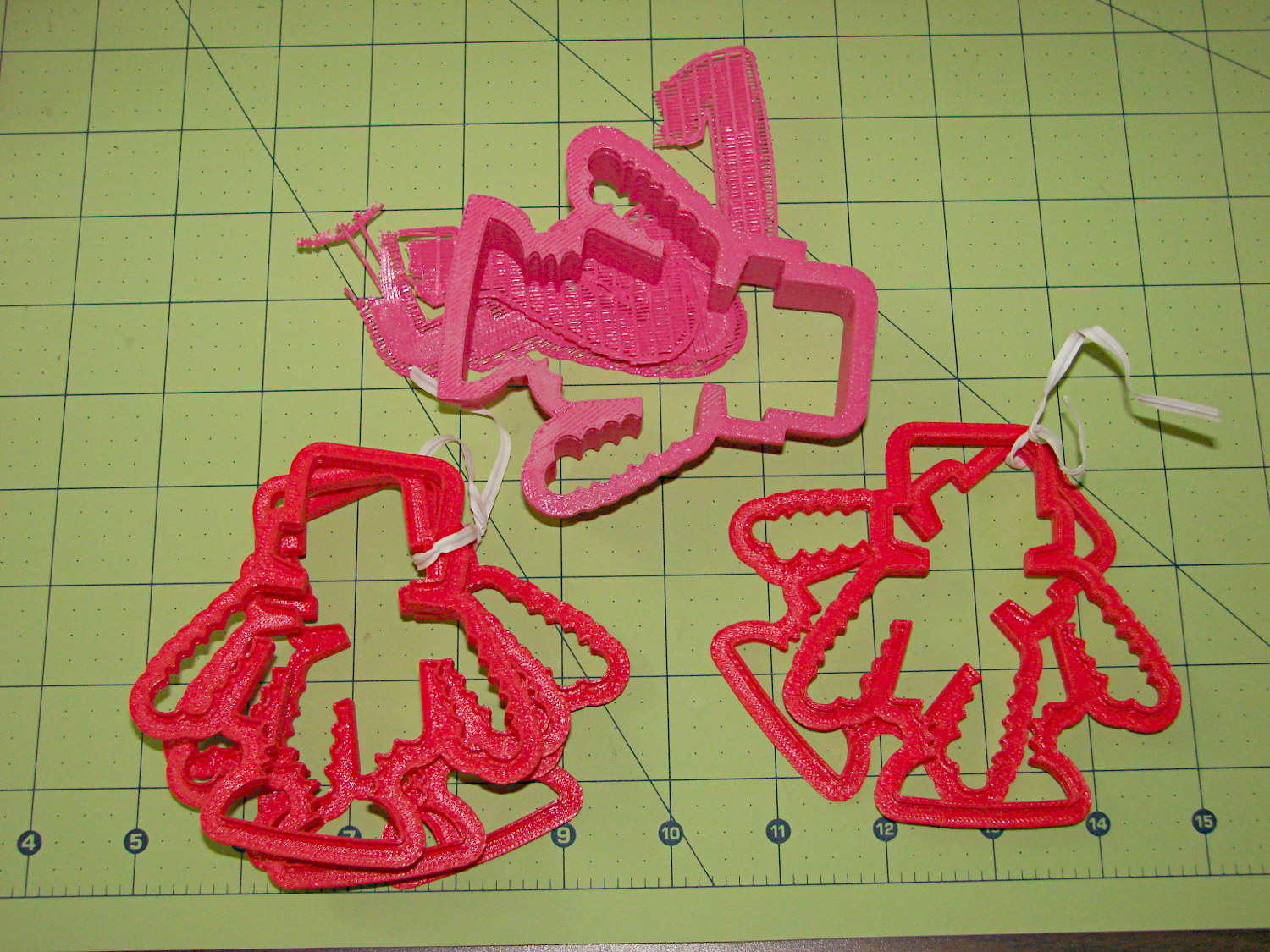
Obviously, that required a bit of fiddling:
Robot Cutter Variations
The pink cutter on the top came from the Afinia, complete with raft. The red cutters, all with short blades to speed up the printing, came from my M2.
The printer mechanics determine the step/mm values for all four axes: X, Y, Z, and the extruder. The effective diameter of the “gear” driving the filament into the extruder seems subject to some quibbling, but setting it so the thinwall box comes out with the proper filament width seems reasonable. Given those four values, the slicing software can control the extruder speed to produce the proper volume of plastic as the XY speed varies.
The slicing software must also know the raw filament diameter, which seems to be consistent within a few percent for the filaments in my collection. Because a 1% change in filament diameter produces a 3% change in extruded volume, a few percent is about all you can tolerate; broad-tolerance filament may require sensors and adjustments that printers don’t currently offer.
There is one remaining variable, essentially a Fudge Factor, which Slic3r calls the extrusion multiplier. This seems to be a linear factor applied to the extrusion volume, so that increasing the factor proportionally increase the flow rate. Given correct step/mm settings and the measured filament diameter, you (well, I) adjust the extrusion multiplier to get the proper extrusion flow. As it turned out, the multiplier I’ve been using with the M2 worked out to 1.00, although I’ve also used 0.97 on occasion. Although I haven’t read the Slic3r source code to verify this, varying the multiplier by +3% should fudge the diameter by about +0.017 mm = 1% of the measured 1.72 mm.
Note that the Makergear-modified Marlin firmware in the M2 will produce different results, as they use a different value for the extruder gear’s effective diameter. More discussion on that is there.
Soooo, I set up the extrusion multiplier to produce parts with accurate dimensions, because that’s what I care about, and didn’t worry too much about perfect surface finish, because I don’t really care about that. Cookie cutters, however, need a completely filled surface that prevents dough from collecting inside, but have essentially no dimensional accuracy requirements.
The quartet of stumpy cutters bundled together on the left of the top photo explored the effect of changing the extrusion multiplier. I used the same STL model for all the cutters and varied only the extrusion factor, so the results depend only on the plastic flow rate and the M2’s impeccable mechanical stability.
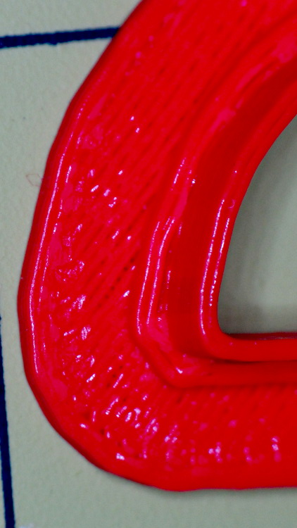
A sharp cusp at 0.96 has a slight opening:
Robot Cutter – 0.96 extrusion multiplier
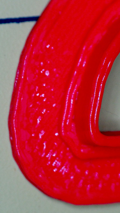
The cusp fills in at 1.10:
Robot Cutter – 1.10 extrusion multiplier
The handle surface is slightly open at 0.96:
Robot Cutter – 0.96 extrusion multiplier
And filled in at 1.10:
Robot Cutter – 1.10 extrusion multiplier
In all those cases, the measured blade thickness varied slightly, but not enough to matter in this application. I didn’t record those numbers and no longer have the models, but … you just tune for best picture.
I picked up five 12 V 40 W cartridge heaters from the usual eBay source for some extruder experiments and did a quick check to make sure they actually worked:
Cartridge heater test
The bench supply is good for 3 A, which isn’t quite enough to light them up all the way, but at 8 V they drew anywhere from 2.67 to 2.20 A, declining by about 0.1 A as they heated over the course of maybe 5 s, which is about as long as you want to run them outside of whatever they’re supposed to be heating.
Those dissipations are a bit lower than I expected; at 8 V you’d expect to see about 27 W = 2/3 * 40 W, not the 18 to 21 W I actually measured. Current & power don’t scale linearly, so I must gimmick up a larger block and make some better measurements when I get the LinuxCNC hardware set up.
The insulating tubes on the wires emerging from the cartridge, inside the main sheath, show the usual attention to detail I’ve come to know and love from eBay suppliers:
Cheap cartridge heater insulation
Ah, well, it keeps my toy budget under control…
There’s a story behind the dark vertical smudge just to the right of the cartridge. More on that in a bit.
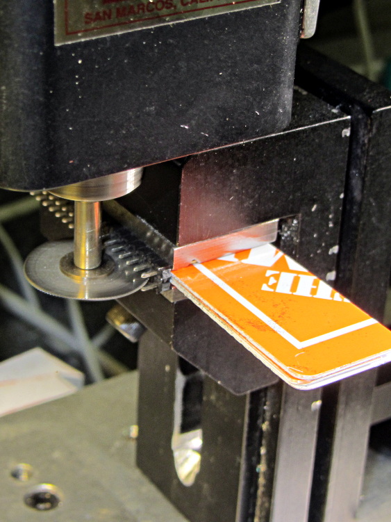
My stock of single-row header pins seems to be running short, so it’s time for another slitting session:
Header pin slicing
Manual CNC, typing bare G-Code directly into LinuxCNC Axis: no reason to turn the cranks by hand.
This makes absolutely no economic sense, but it’s a sticky-hot day and the Basement Laboratory has the dehumidifier. Some day I’ll run into a killer surplus sale of single-row headers and that’ll solve the problem forever…
The Basement Warehouse Wing has an essentially unlimited supply of pristine CD cases (remember CDs?) that, with a bit of deft bandsaw work, will each emit a pair of 4×4 inch sheets of perfectly transparent acrylic plastic. The sheets are about 1.3 mm = 50 mils thick, which is just about exactly what you want for a Nixie-style display that doesn’t require high voltages, because you can edge-light a sheet with 0603 amber SMD LEDs. Obviously, this is not a Shining New Idea, but this post collects my doodles so they don’t get lost along the way.
The Squidwrench StickerLab session prodded me into lashing a prototype together to see how this would work; they have a Silhouette Cameo vinyl cutter driven with Robotcut that works well. I’d hoped to do some laser cutting at the subsequent session, but our schedules didn’t mesh.
The compelling advantage of laser cutting is that you could crack the CD cases apart, throw out the CD holder gimcrackery, lay the sheets flat on the cutter table with the latches & other junk upward, and burn the digits out of the middle without any further preparation. I think I could get much the same effect, at least for a crude prototype, by milling & engraving with the Sherline.
The sheets are about 4 threads of 3D printed plastic extruded at the M2’s default 0.4 mm width. You could print a black baseplate with slots to hold the sheets, put two threads between each sheet, and have the sheet 6 threads apart on center = 2.4 mm spacing:
Tab vs 3D thread size doodle
Ten such sheets would produce a standard 0-to-9 display about an inch deep, plus protective sheets front and back, so the whole affair would be maybe 1.25 inch deep. You’d probably want to offset the tabs on adjacent sheets to reduce light leakage between LEDs. The baseplate fits atop a PCB with LEDs at the right locations, so you get an opaque holder for the sheets that’s easy to produce and easy to assemble:
Sheet tab layout doodle
If you were clever, you could have different tab locations on each sheet so they’d fit only in the proper orientation; that might be important for cough mass production.
The M2 has a platform big enough to build an entire clock base in one pass, plus a matching piece to capture the tops of the digits. I think edge-lit acrylic needs a complete opaque surround for each digit sheet to block light leaking from the edges; it might be easier to build the mount in the other direction, lying flat on the platform, stack the mounts together with the digit sheets, then bolt the whole assembly from the front; that would ensure perfect alignment of everything.
In that case, the 3D printed layers are 0.25 mm (or smaller), but the resolution for the tabs would be 0.4 mm. If you were exceedingly brave & daring, you could lay the digit sheets in place during the build and come out with a monolithic unit; that might require a bit of clearance atop each sheet, as a grazing touch from a hot nozzle would be painfully obvious.
There’s also no reason you couldn’t use a wider “digit” sheet and engrave, say, the days of the week or the units of measurement or something like that on each panel.
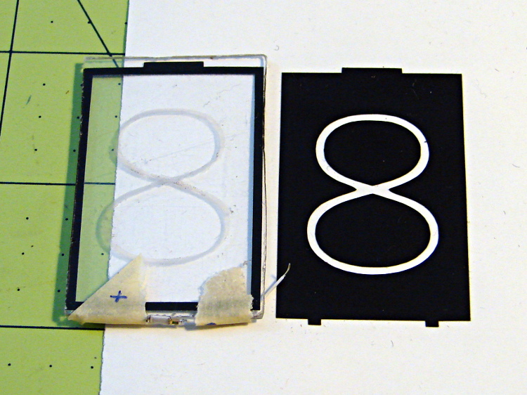
If the display will be 30 mm deep, then the digits must be large enough that the depth doesn’t turn each digit into a tunnel. Large Nixe tubes had digits about 40 mm tall, so I went with a 30 x 45 panel, plus 1 mm tabs on the top and bottom:
Crude edge-lit acrylic panel vs vinyl stencil
The “engraved” digit on the left came from a vinyl mask similar to the one on the right, using fine sandpaper to rough up the acrylic surface. I deliberately started with a battered old CD case in order to prevent myself from getting too compulsive with neatness; as you’ll see, edge-lit acrylic reveals any surface imperfections, so cleanliness is important.
The black border could be a light-shield gasket around the outer edge of the display panel to reduce glare from the edges. This might be more important for laser-cut pieces with highly reflective edges or for milled pieces with diffuse edges; there’s no way to tell without actually building one to see. I simply bandsawed the sheet around the edges of the mask, then filed off the larger chunks: the edges are very, very rough, indeed.
There doesn’t seem to be an easy way to stash the Inkscape SVG file on WordPress.
I solder-blobbed some wire-wrap wire, a 1206 SMD resistor, and a 0603 LED together:
Crude 0603 SMD LED lashup
The 0603 SMD LED fits neatly along the edge of the sheet:
0603 SMD on CD case edge
A 3rd hand holds it upright on the bench over the LED lashup:
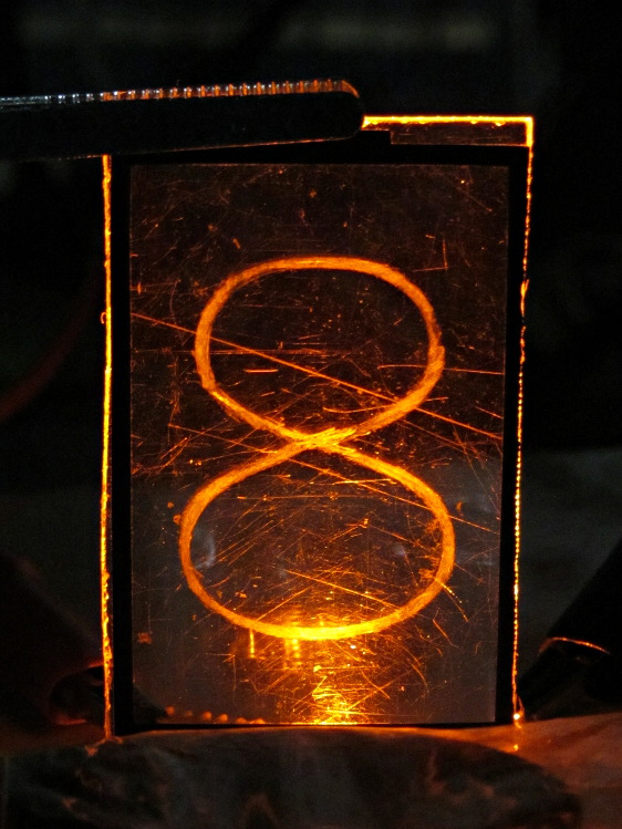
Edge-lit acrylic – front layout
It looks marginally better with the lights out, but you can see all the scratches:
Edge-lit acrylic – front detail
The hot spot at the bottom of the digit isn’t nearly that awful in person.
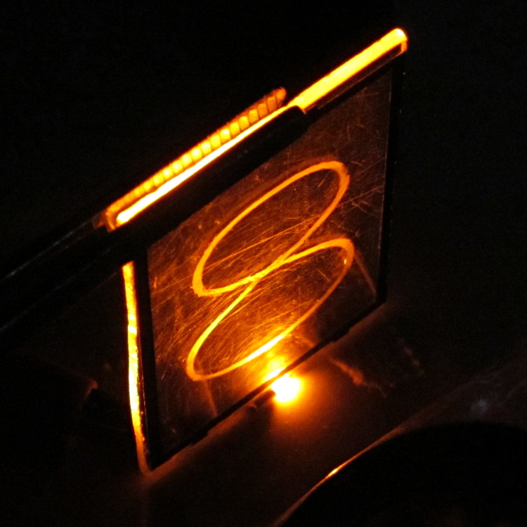
A top view shows the glowing edges, plus the nuclear glow from the LED:
Edge-lit acrylic – top view
A touch of soft focus, plus moving the LED under a tab location, helps a bit:
Edge-lit acrylic – front soft focus
You’d want two LEDs per digit and maybe one at the top, but that’s in the nature of fine tuning.
All in all, I like how it looks. Getting from this crud to a workable display will require far more effort than I can devote to it right now…
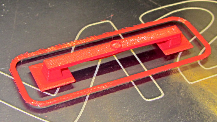
Although I’ve pretty much given up on torture tests, I saw a note about the troubles someone had with Triffid Hunter’s Bridge Torture Test object. I did a bit of tweaking to the OpenSCAD source to shorten the struts and add the pads (which could be done with Slic3r’s Brim settings), but it’s otherwise about the same. The clear span is about 50 mm:
Bridge Torture Test – solid model
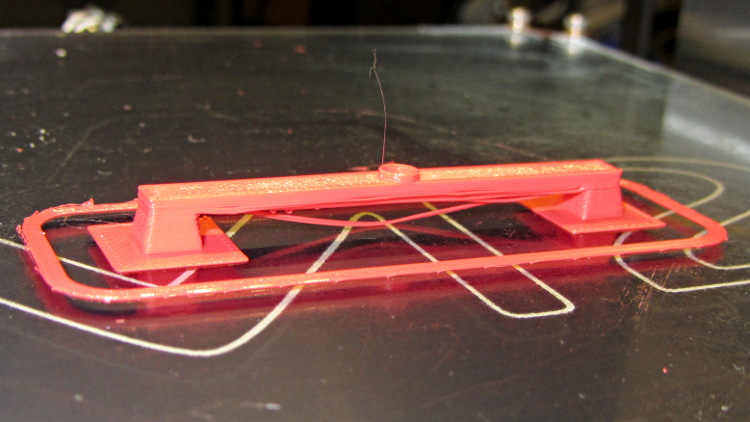
Using my usual settings, with no special setup, the front looked OK:
Bridge torture test – overview
One strand came out rather droopy:
Bridge torture test – front
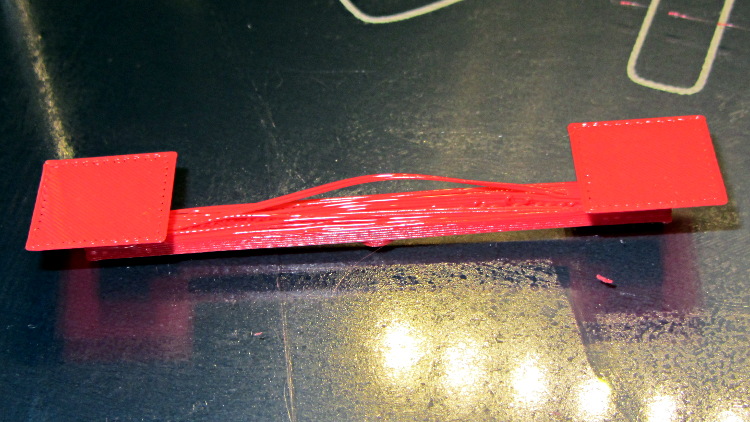
The bottom layer of the bridge isn’t as consolidated as it could be:
Bridge torture test – bottom
The overall speed dropped considerably as the Cool setting limited the layer time to 20 seconds; the Bridge settings didn’t apply.
I could probably tighten the bottom strands a bit, but it’s OK for a first pass.
Alas, the nice slotted cap I put on the driveway drain can’t handle the amount of debris released by the trees next to the house and above the gutters. I’d removed the thumbscrew to simplify clearing the cap whenever I go for the mail, but that just accentuated the problem:
Driveway drain – fountain
The backup must be over a foot of water at the end of the pipe; that fountain emerges from the 1/4 inch hole for the thumbscrew. Fortunately, the slope is large enough that the water (probably) isn’t backing up into the retaining wall footing drain.
When the pine trees toss their dead needles overboard, the cap plugs solid and, minus the screw, blows across the driveway:
Driveway drain – clogged
It usually doesn’t roll very far, although I’ve retrieved it halfway to the street.
I still think the chipmunks will move in without a grate blocking the pipe, but I’m unsure how to proceed…