The Smell of Molten Projects in the Morning

Ed Nisley's Blog: Shop notes, electronics, firmware, machinery, 3D printing, laser cuttery, and curiosities. Contents: 100% human thinking, 0% AI slop.

Category: Machine Shop

Mechanical widgetry

  • Free Motion Quilting Darning Foot Modification: The Home Shop Way

    Mary has been learning free motion quilting, which uses a special sewing-machine foot that holds the fabric in place. Leah Day describes modifying a standard darning foot, but I suggested deploying a bit more shop-fu to do it right. The notion of “adjusting” something with a twisted rubber band just made my skin crawl…

    The starting point is a Brewer BP1814 “FOOT Darning/Quilting low shank with clear base”, two of which appear next to an older version that she’s had for quite some time. The rightmost one has my modifications:

    Brewer BP1814 Quilting Foot - assortment
    Brewer BP1814 Quilting Foot – assortment

    The older (mostly metal) foot works much better for its intended purpose, but the newer white plastic version seems easier to modify for free-motion quilting. The older spring is much softer than the new ones, for whatever that’s worth. After the modification, the spring pressure becomes largely irrelevant, as it only acts when something pushes up on the base.

    The first modification improves visibility by cutting out part of the transparent plastic base. Leah suggests chopping it with a diagonal cutter (“jewelry clippers”), but I deployed a slitting saw in the Dremel tool at low speed to avoid melting. Mary wanted angled cuts, so that’s what she got:

    Modified Darning Foot - opened base
    Modified Darning Foot – opened base

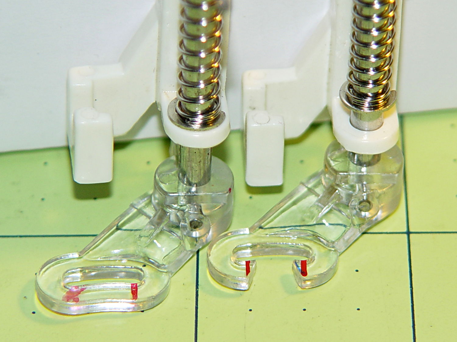
    A bit of touchup with a fine file smoothed out the edges so the base slides easily over the fabric. There’s no way to remove the red guide lines; the un-modified foot on the left emerged from its bag with that smeared line.

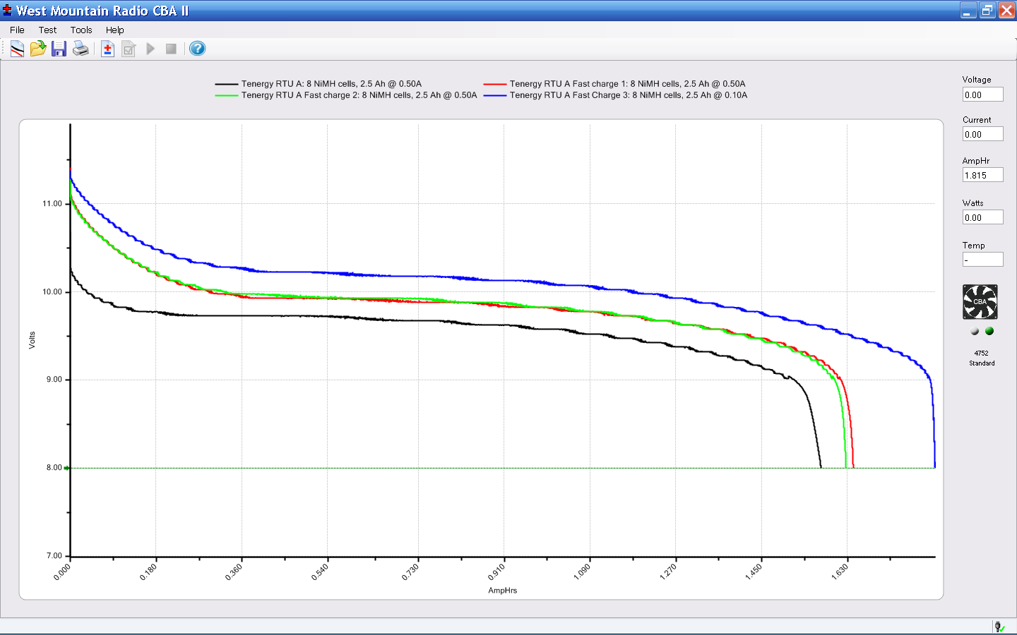
    Then drive out the top metal pin with a small drift punch, hold the base and shaft, remove the C-clip, capture the spring, and extract the base and shaft. The 4.0 mm diameter metal shaft cries out to be threaded, so that’s what I did; this picture shows the reassembled shaft and spring:

    Modified Darning Foot - threaded shaft
    Modified Darning Foot – threaded shaft

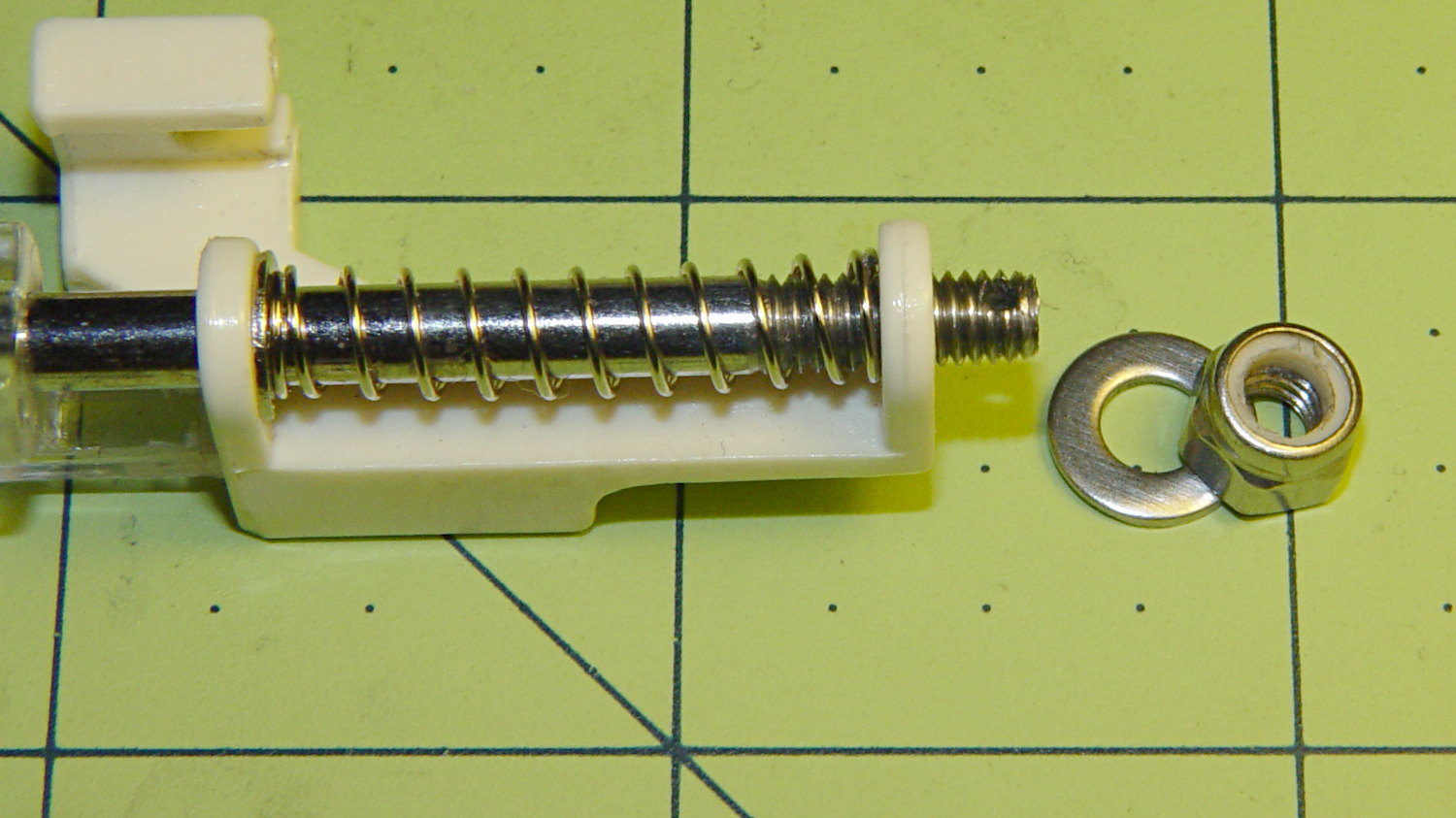
    That’s significantly harder to accomplish than it looks, because there’s no practical way to remove the plastic base (it’s pinned in place, but one side of the cross-hole is blocked). I filed the end of the shaft to a taper that started the M4.0x0.7 die a bit more easily, clamped the shaft in the bench vise, applied nasty sulfur-based tapping fluid, crossed my fingers and eyes, held my nose, and managed to make it happen without cracking the plastic.

    I reamed out the Nyloc nut with a hand-twisted series of drills, through about #24 = 3.861 mm, to reduce the locking torque. It’s now just slightly more than finger-tight, which should suffice.

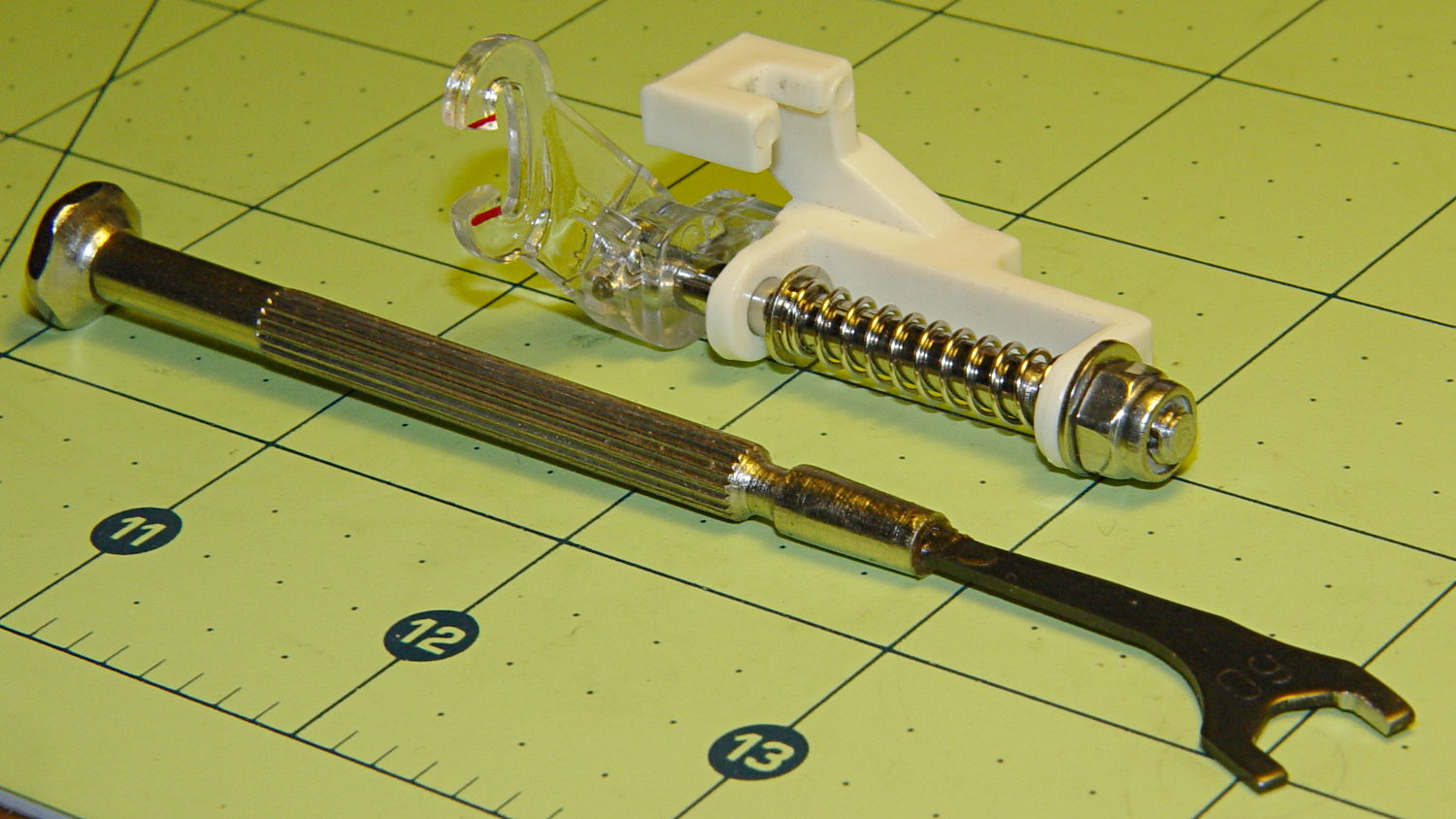
    In use, the foot fits under the sewing machine’s arm and puts the nut where fingers can’t reach. I filed a 6.0 mm “precision wrench” to fit the 6.8 mm nut flats and it’s All Good:

    Modified Darning Foot - assembled with wrench
    Modified Darning Foot – assembled with wrench

    A staged photo op atop some trial quilting:

    Modified Darning Foot - in action
    Modified Darning Foot – in action

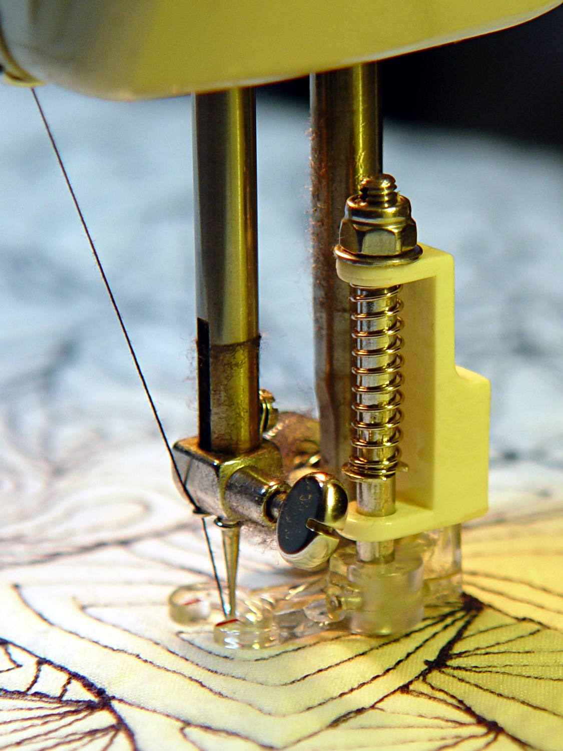
    With a Nyloc nut instead of a rubber band, it will stay exactly where she wants it…

  • FC1002 Frequency Counter Battery Pack

    The main reason for taking the FC1002 frequency counter apart was to replace the failed quad-AA NiCd battery pack. Rather than buy new cells with tabs, I recycled some low-discharge “ready to use” NiMH cells from the heap. Back in 2009, they looked like this:

    Tenergy RTU Pack A Tests - Aug 2009
    Tenergy RTU Pack A Tests – Aug 2009

    Nowadays, they’re a bit less peppy:

    Tenergy RTU - 2014-01 - loose cells
    Tenergy RTU – 2014-01 – loose cells

    The red blooper shows that you can’t trust a smart fast charger to get the right answer; it concluded that pair was fully charged. After the discharge test and an overnight C/10 charge, they regained as much enthusiasm as they’ll ever have.

    They have slightly less capacity than in 2009 and also a somewhat lower terminal voltage. That shouldn’t matter here, as the frequency meter has a power supply to take care of that problem.

    Although I’ve sometimes been able to (quickly!) solder directly to ordinary AA cells, a trial run on a defunct RTU cell showed that wasn’t going to work on whatever variety of steel they used, no matter how much I scuffed it and despite using aggressive flux that normally blends silver solder onto stainless steel.

    Fortunately, the top half of a four cell case fit exactly in the space available, so I used woven copper fabric tape inside the case to interconnect the cells, then lashed everything together with the obligatory Kapton tape:

    FC1002 Frequency Counter - battery pack
    FC1002 Frequency Counter – battery pack

    That cracked faceplate isn’t the nicest thing to confront, but it’ll suffice until I get more motivation:

    FC1002 Frequency Counter - repaired
    FC1002 Frequency Counter – repaired

    I’ve misplaced my stack of Round Tuits again…

  • Toyota Sienna: Key Wear

    And it came to pass in the Christmas Season that our ignition keys began jamming in the lock, rather than just starting the van. It seems Toyota used split wafers in their locks up through the early part of this millennium, with the result that the delicate wafer edges tend to wear out both themselves and the edges of the keys.

    I can’t vouch for the wafers, but the keys definitely aren’t in good shape:

    Ignition keys - worn vs new
    Ignition keys – worn vs new

    Given that picture, someone can probably conjure up a shiny new key and drive away with our 14-year-old Sienna van. It just rolled over 90 k miles and is in pretty good condition. New battery and hood prop pivot, too.

    Being that type of guy, the first thing I did with the new van was to get duplicate keys and drop the OEM keys into the “2000 Sienna” file folder. The middle key in that photo has had maybe a dozen uses and is in pristine condition.

    Rumor has it that one can cannibalize a set of split wafers from the glove box lock:

    Glove box latch
    Glove box latch

    Or, according to different sources, you can simply discard the split wafers and be done with it.

    The trick to removing the lock cylinder lies in turning the key to the Accessory position, then poking a pointy object into a small hole to depress an internal spring-loaded pin. Of course, one must disable the air bags, dismantle the steering wheel, and remove half a dozen trim panels to reveal the small hole.

    Fortunately, the two “new” keys from the file folder work perfectly and we’ll run with them for a while. I suppose I should get another set of duplicates, but …

  • Caig DeoxIT Bottle: Lid Crack

    For years this bottle of DeoxIT has been covered with a very thin layer of red juice, despite having the lid screwed firmly in place and a cap (removed here) pushed over the tube:

    Caig DeoxIT bottle - lid crack repair
    Caig DeoxIT bottle – lid crack repair

    Turns out that there’s a minute crack in the cap. Every time I use the bottle, I refresh the oil layer on the inside of the bottle, which then gets pumped outside through capillary action. I’d been keeping the bottle in a tall ziploc baggie, specifically to contain the oil, and always assumed it was a simple leak.

    The bottle still contains a lifetime supply of DeoxIT that may become a cherished family heirloom, one to be handed down through the generations. I can’t think of a better applicator, either, so I’m kind of stuck with that cap.

    The cap is, of course, un-bondable polyethylene covered with thin oil, so there’s no possible way to repair it. I wiped it down with alcohol and acetone, then quick-like-a-bunny dabbed on a blob of Duco cement (which is the irregular shape on the cap) and worked it into the crack, in the hope it would stick well enough to reduce the pumping.

    We shall see…

  • FC1002 Frequency Counter Faceplate Repair

    The plastic faceplate over the display cracked quite a while ago:

    FC1002 Frequency Counter - cracked plastic
    FC1002 Frequency Counter – cracked plastic

    I don’t recall dropping the poor thing. Given the interesting pattern, it could be inherent stress that finally let loose as the plastic aged.

    While I have it apart to rebuild the battery pack (more on that later), I’ve been easing acetone/MEK into those cracks by capillary attraction in the hopes of dissolving just enough plastic to rejoin them, without slobbering solvent all over the faceplate and scarring it.

    If all else fails, I suppose I can mill out a replacement from thin acrylic sheet, but those nicely rounded cast / molded edges lie well beyond my abilities…

  • MHV LUG Lightning Talk: Intro to NSA Hardware Implants

    Meme - Nixon - I see what you did there - 5x38k
    Meme – Nixon – I see what you did there – 5x38k

    I did five minutes of standup comedy at yesterday’s MHV Lug meeting, pointing out some of the more interesting ways to compromise a PC when you have an infinite budget for development and consumables.

    You don’t get my patter with the PDF (unless you had access to the room’s bugging hardware), but the links may come in handy in the unlikely event you haven’t been following the story closely.

    If you have a security clearance or are in line for one, you probably shouldn’t click on the link, because it contains copies of pages from the leaked NSA catalog:

    I See What You Did There – NSA Hardware Guide

  • Water Cooled Stepper Motors: Flow Calculation

    A discussion on the Makergear Google Group about a heated enclosure prompted me to run the numbers for cooling stepper motors with water, rather than fans and finned heatsinks.

    The general idea comes from my measurements of the air-cooled heatsink stuck to a stepper’s end cap. The metal-to-metal conductivity works surprisingly well and reduces the case temperature to slightly over ambient with decent airflow through the heatsink; epoxying a cold plate to the end cap should work just as well. A NEMA 17 stepper case is 42.3 mm square, so a standard 40 mm square CPU cooling plate will fit almost exactly.

    The question then becomes: how much water flow do you need to keep the motors cool?

    Some numbers:

    • Water’s heat capacity is 4.2 J/g·K
    • 1 J = 1 W·s, 1 W = 1 J/s
    • NEMA 17 motors dissipate about 5 W (13 W if you’re abusing them)
    • We’ll cool all four motors in parallel, for a total of 20 W
    • Allow a 5 K = 5 °C temperature rise in each cold plate

    Rub them all together:

    (20 J/s) / (5 K * (4.2 J/g·K)) = 0.95 g/s

    For water, 1 g = 1 cc, so the total flow is 1 cc/s = 3600 cc/h = 3.6 liter/h, which, here in the US, works out to a scant 1 gallon/hour. It’s tough getting a pump that small and cheap flowmeters run around 0.5 liter/m…

    If you don’t want a pump. put an aquarium up on a (sturdy) shelf and drain it through the cold plates. A cubic foot of water, all eight gallons and sixty-some-odd pounds of it, will last 8 hours, which should be enough for most printing projects.

    If you want reliability, drain the coolers into a sump with a float switch (high = on), put another float switch (high = off) on the aquarium, and have the pump top up the aquarium. If the pump fails, your steppers stay cool for the next 8 hours. Heating the water about 5 °C during 8 hours won’t require active cooling.

    Now, managing the hoses leading to the X axis stepper may be challenging, but a cable drag chain would control the rest of the wiring, too.