Ed Nisley's Blog: Shop notes, electronics, firmware, machinery, 3D printing, laser cuttery, and curiosities. Contents: 100% human thinking, 0% AI slop.
The fancy OXO can opener doesn’t work well on #10 cans, so we bought a not-bottom-dollar can opener with comfy handles to replace the one that convinced us to get the OXO. After maybe a year, tops, it gradually stopped working well, too, which prompted a trip to the Basement Shop Workbench.
The symptoms:
The handle wouldn’t move the cutter during maybe 1/4 of its revolution
It pushed the handles apart during another quarter turn
Look carefully and you’ll see the teeth sticking out slightly more on the right side of the drive wheel:
Can opener – drive gear misalignment
When those protruding teeth line up with the gear behind the cutter wheel, the handles open and the drive wheel loses its grip. When the low side lines up with the cutter gear, the gears very nearly disengage.
Taking it apart shows that both “gears” (which is using the term loosely) have been pretty well chewed up:
Can opener – gears and cutters
Destroying those gears should require a lot more strength than either of us can deploy on a regular basis, which suggests they used mighty soft steel. It’s not obvious, but the drive gear hole is just slightly larger than the screw thread OD; it doesn’t ride on an unthreaded part of the screw shaft.
I’m not in the mood for gear cutting right now, so I filed down the wrecked teeth and buttoned them up with some attention to centering the gear. The can opener works, but sheesh this is getting tedious…
The Sony HDR-AS30V “action camera” uses NP-BX1 lithium batteries (3.7 V @ 1.24 A·h = 4.6 W·h) that are, of course, a completely different size and shape than any other lithium battery on the planet.
So.
Tweaking a few dimensions in the Canon NB-6L source code, tinkering with the layout of the contact pins, and shazam Yet Another 3D Printed Battery Test Fixture:
NP-BX1 Holder – show layout
It builds nicely, although the contact pin tunnels are a bit too close to the top of the case:
Sony NP-BX1 Holder – on platform
After reaming out the contact pin holes to the proper diameters & depths, then gluing the plugs in place, it works just as you’d expect:
Sony NP-BX1 battery holder
It’s worth noting that the Wasabi charger accepts the batteries upside-down, with the conspicuous chevron against the charger body. It’s definitely not the way all the other chargers work. The keying recesses on the battery (corresponding to the blocks in the solid model) lie along the bottom edge of the contact surface, so flipping the battery over means they’ll hold it in place, but … oh, well.
That grotty Powerpole connector last saw use in some random benchtop lashup. At some point I’ll be forced to start making more of those.
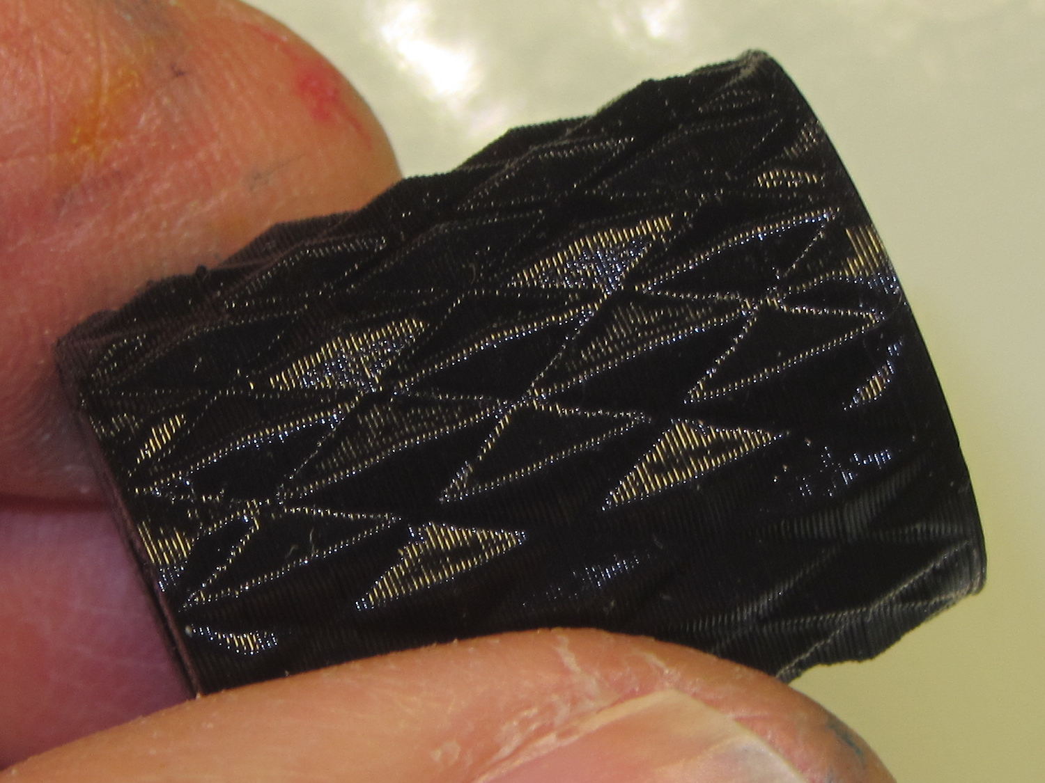
These quilting pin caps are slightly longer than the previous version and, due to the M2’s smaller nozzle, have slightly thinner single-thread walls. Because Slic3r does a better (although not ideal) job of path planning than Skeinforge, it’s easier to create an array of the caps in the solid model than to manually add duplicates in Slic3r:
Fill with silicone caulk on waxed paper and they look even more like that:
Quilting pin caps – silicone fill
Fast-forward a few days, rub off the excess caulk, trim off a few blobs, and they’re ready for presentation:
Quilting pin caps – finished
In use, they look about like you’d expect:
Quilting pin caps – in use
The pin caps I made from a 5 gallon bucket’s O-ring gasket didn’t work out well, as the plastic didn’t like being poked with pins and put up a stiff resistance. Silicone caulk has exactly the right consistency.
When Mary ramps up a full-scale quilt, we’ll need a few hundred of the things. The commercial version has dropped to 40 cents each, which makes all this worthwhile.
The OpenSCAD source code:
// Quilting pin caps
// Ed Nisley KE4ZNU April 2012
//	January 2013 - modify for Slic3r and M2

//- Extrusion parameters must match reality!
//  Print with +1 shells and 3 solid layers

ThreadThick = 0.20;
ThreadWidth = 0.40;

HoleWindage = 0.2;

function IntegerMultiple(Size,Unit) = Unit * ceil(Size / Unit);

Protrusion = 0.1;			// make holes end cleanly

//----------------------
// Dimensions

ID = 5.0;
OD = ID + 2*ThreadWidth;
Length = 8.0;
Sides = 8;

CapArray = [6,6];			// XY layout of caps
CapsOC = OD + 2.0;			// OC spacing

//----------------------
// Useful routines

module PolyCyl(Dia,Height,ForceSides=0) {			// based on nophead's polyholes

  Sides = (ForceSides != 0) ? ForceSides : (ceil(Dia) + 2);

  FixDia = Dia / cos(180/Sides);

  cylinder(r=(FixDia + HoleWindage)/2,
           h=Height,
	   $fn=Sides);
}

module ShowPegGrid(Space = 10.0,Size = 1.0) {

  RangeX = floor(100 / Space);
  RangeY = floor(125 / Space);

	for (x=[-RangeX:RangeX])
	  for (y=[-RangeY:RangeY])
		translate([x*Space,y*Space,Size/2])
		  %cube(Size,center=true);

}

module PinCap() {
	rotate(180/Sides) {
		difference() {
		PolyCyl(OD,Length,8);
		translate([0,0,-Protrusion])
			PolyCyl(ID,(Length + 2*Protrusion),8);
		}
	}

}

//----------------------
// Build them!

ShowPegGrid();

translate([(-CapsOC*(CapArray[0] - 1)/2),(-CapsOC*(CapArray[1] - 1)/2),0])
	for (i=[0:(CapArray[0] - 1)],j=[0:(CapArray[1] - 1)])
		translate([i*CapsOC,j*CapsOC,0])
			PinCap();
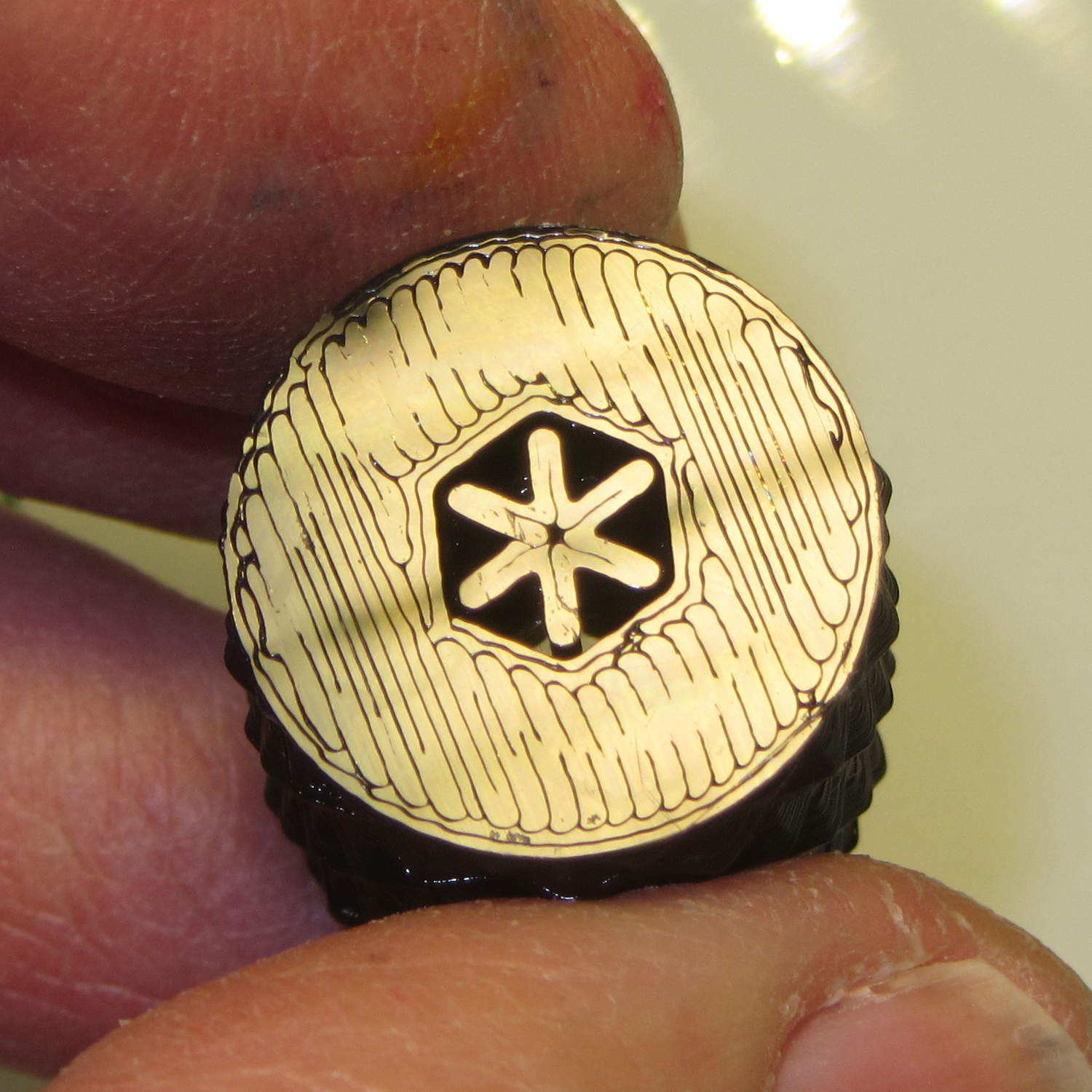
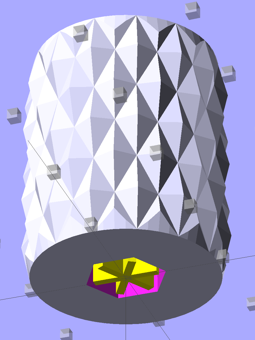
A discussion on the OpenSCAD mailing list about making a rectangular solid with rounded edges having different radii eventually produced this delightful result:
Basic Rounded Cube
Those guys make me feel dumb, because they’re generally solving problems I can’t even imagine, but I know what to do with this solution. One could slice it in half horizontally, emboss a height map defining a logo / picture into the top surface, print it out on your favorite 3D printer, maybe smooth / seal the surface a bit, define it to be a positive mold pattern, cast / pour flexible silicone around it, and get a negative mold for a pourable precious material such as, oh, chocolate.
You could make half a dozen of them, arrange them inside a suitable printed frame, pour the silicone, and get a multi-cavity mold for better manufacturing productivity.
The overall block lacks draft, because the problem it solves presumes you need a block of specific outside dimensions: it overlays three full-size rectangular blocks that define the dimensions. OpenSCAD constructs spheres such that they may be slightly smaller than the defined radius at the poles and, depending on their alignment, a face at the equator may reduce the outer dimension of a surrounding hull.
Given a sufficiently bendy silicone mold, you might not need any draft at all. If you do need draft and you don’t care about a very slightly undersized pattern, remove the internal blocks and increase the XY spacing of the lower four spheres by enough to make the draft come out right.
The grayscale logo / image should have nice smooth transitions that produce suitable draft for the fine details; a bare black-and-white image might not work well. Shallow is good, but that conflicts with 3D printing’s crappy resolution: 1 mm = 10 layers, tops. That might not matter in practice.
You’re supposed to temper the chocolate, but that’s probably more relevant for Fine Art molds.
The Thing-O-Matic hardware isn’t up to the standards of, say, an M2, but, after all my tweakage, it’s Good Enough for most purposes. These Slic3r settings should provide a reasonable starting point to get it working the way it used to with its new controller.
The key extrusion dimensions:
0.4 mm nozzle → 0.5 mm minimum thread width
0.25 mm layer thickness
The speeds come from the old Skeinforge configuration, dialed back a bit for sanity:
150 mm/s non-printing XY travel
10 mm/s minimum printing speed
20 mm/s first layer printing for better adhesion
40 mm/s general printing
60 mm/s infill
Some of the finer settings are completely arbitrary and everything requires tweaking, along with Marlin’s acceleration & jerk settings, for best picture.
The exported Slic3r configuration:
# generated by Slic3r 1.0.0RC1 on Fri Jan 17 11:25:02 2014
avoid_crossing_perimeters = 0
bed_size = 105,120
bed_temperature = 110
bottom_solid_layers = 3
bridge_acceleration = 0
bridge_fan_speed = 100
bridge_flow_ratio = 1
bridge_speed = 40
brim_width = 0
complete_objects = 0
cooling = 1
default_acceleration = 0
disable_fan_first_layers = 1000
duplicate = 1
duplicate_distance = 6
duplicate_grid = 1,1
end_gcode = ;---- end.gcode starts ----\n; TOM 286 - Al plates + Geared extruder\n; Ed Nisley - KE4ZNU - January 2014\n; Marlin with tweaks for Azteeg X3 with thermocouple\n;- inhale filament blob\nG91\nG1 E-5 F900\nG90\n;- turn off heaters\nM104 S0         ; extruder head\nM140 S0         ; HBP\n;- move to eject position\nG1 Z999 F1000   ; home Z to get nozzle away from object\nG92 Z115      ; reset Z\nG1 X0 F6000     ; center X axis\nG1 Y35          ; move Y stage forward\n;---- end.gcode ends ----
external_perimeter_speed = 50%
external_perimeters_first = 0
extra_perimeters = 1
extruder_clearance_height = 20
extruder_clearance_radius = 20
extruder_offset = 0x0
extrusion_axis = E
extrusion_multiplier = 1.00
extrusion_width = 0.50
fan_always_on = 0
fan_below_layer_time = 1
filament_diameter = 2.95
fill_angle = 45
fill_density = 0.15
fill_pattern = honeycomb
first_layer_acceleration = 0
first_layer_bed_temperature = 110
first_layer_extrusion_width = 0.50
first_layer_height = 0.25
first_layer_speed = 20
first_layer_temperature = 200
g0 = 0
gap_fill_speed = 30
gcode_arcs = 0
gcode_comments = 0
gcode_flavor = reprap
infill_acceleration = 0
infill_every_layers = 3
infill_extruder = 1
infill_extrusion_width = 0.50
infill_first = 1
infill_only_where_needed = 1
infill_speed = 60
layer_gcode =
layer_height = 0.25
max_fan_speed = 100
min_fan_speed = 35
min_print_speed = 10
min_skirt_length = 5
notes =
nozzle_diameter = 0.4
only_retract_when_crossing_perimeters = 1
ooze_prevention = 0
output_filename_format = [input_filename_base].gcode
overhangs = 1
perimeter_acceleration = 0
perimeter_extruder = 1
perimeter_extrusion_width = 0.50
perimeter_speed = 40
perimeters = 2
post_process =
print_center = 0,0
raft_layers = 0
randomize_start = 1
resolution = 0.05
retract_before_travel = 0.5
retract_layer_change = 0
retract_length = 2
retract_length_toolchange = 10
retract_lift = 0
retract_restart_extra = 0
retract_restart_extra_toolchange = 0
retract_speed = 60
rotate = 0
scale = 1
skirt_distance = 2
skirt_height = 1
skirts = 3
slowdown_below_layer_time = 15
small_perimeter_speed = 50%
solid_fill_pattern = rectilinear
solid_infill_below_area = 5
solid_infill_every_layers = 0
solid_infill_extrusion_width = 0.50
solid_infill_speed = 150%
spiral_vase = 0
standby_temperature_delta = -5
start_gcode = ;---- start.gcode begins ----\n; TOM 286 - Al plates + Geared extruder + Zmin platform sense\n; Ed Nisley - KE4ZNU - January 2014\n; Marlin with tweaks for Azteeg X3 with thermocouple\n;\n; Set initial conditions\nG21                 ; set units to mm\nG90                 ; set positioning to absolute\n;----------\n; Begin heating\nM104 S[first_layer_temperature]         ; extruder head\nM140 S[first_layer_bed_temperature]    ; start bed heating\n;----------\n; Home axes\nG28 X0 Y0 Z0\nG92 X-53.5 Y-58.5 Z115.0\n;----------\n; Initial nozzle wipe to clear snot for Z touchoff\nG1 X0 Y0 Z3.0 F1500     ; pause at center to build confidence\nG4 P1000\nG1 Z10                  ; ensure clearance\nG1 X39 Y-58.0 F10000    ; move to front, avoid wiper blade\nG1 X55                  ; to wipe station\nG1 Z6.0                 ; to wipe level\nM116                    ; wait for temperature settling\nG1 Y-45 F500            ; slowly wipe nozzle\n;-----------------------------------------------\n; Z platform height touchoff\n; Make sure the XY position is actually over the switch!\n; Home Z downward to platform switch\n; Compensate for 0.05 mm backlash in G92: make it 0.05 too low\nG1 X56.0 Y8.2 Z4.0 F6000     ; get over build platform switch\n;G1 Z0 F50                    ; home downward very slowly\n;G92 Z1.45                    ; set Z-min switch height\nG1 Z6.0 F1000                ; back off switch to wipe level\n;-----------------------------------------------\n; Prime extruder to stabilize initial pressure\nG1 X55 Y-45 F6000   ; set up for wipe from rear\nG1 Y-58.0 F500      ; wipe to front\nG91                 ; use incremental motion for extrusion\nG1 F2               ; set slow rate\nG1 E10              ; extrude enough to get good pressure\nG1 F4000            ; set for fast retract\nG1 E-2.0            ; retract\nG90                 ; back to absolute motion\nG1 Y-45 F1000       ; wipe nozzle to rear\n;----------\n; Set up for Skirt start in left rear corner\n; Compensate for Z backlash: move upward from zero point\nG1 X-50 Y55 Z0.0 F10000     ; left rear corner -- kiss platform\nG1 Z0.2 F1500       ; take up Z backlash to less than thread height\nG92 E1.0            ; preset to avoid huge un-Reversal blob\n;G1 X0 Y0\n;---- start.gcode ends ----
start_perimeters_at_concave_points = 1
start_perimeters_at_non_overhang = 1
support_material = 0
support_material_angle = 0
support_material_enforce_layers = 0
support_material_extruder = 1
support_material_extrusion_width = 0.50
support_material_interface_extruder = 1
support_material_interface_layers = 3
support_material_interface_spacing = 0
support_material_pattern = honeycomb
support_material_spacing = 2.5
support_material_speed = 60
support_material_threshold = 0
temperature = 200
thin_walls = 1
threads = 2
toolchange_gcode =
top_infill_extrusion_width = 0.50
top_solid_infill_speed = 50%
top_solid_layers = 3
travel_speed = 150
use_firmware_retraction = 0
use_relative_e_distances = 0
vibration_limit = 0
wipe = 0
z_offset = 0
Shortly after replacing the battery, the dreaded Malfunction Indicator Lamp popped on with a P0420 error code that, according to the Nice Man at Autozone, translates into “low catalytic converter efficiency”. A bit of diagnostic sleuthing reported that the most likely cause was an exhaust leak, followed by an out-of-calibration downstream oxygen sensor, followed by a bad converter. Internet lore has it that replacing the cat cracker is a dealer-only event (here in New York State, with a van sporting the California emissions package) that costs upwards of $2 k, which seems excessive for a 14-year-old van.
Actually, the most probable cause was replacing the battery: the brief power outage wipes out the stored performance data for the emissions control machinery. Because we make only short trips and it’s been bitterly cold, the algorithms may conclude the converter’s dead when it’s just a matter of measuring the variables under suboptimal conditions.
With all that in mind, after a peek under the van ruled out the exhaust leak, I decided to replace the oxygen sensor. All this happened during a week when the outdoor temperature hovered around 10 °F = -12 °C, but the forecast called for an atypical January day with a high of 55 °F = 13 °C; I might not get a second chance before the annual inspection came due in February.
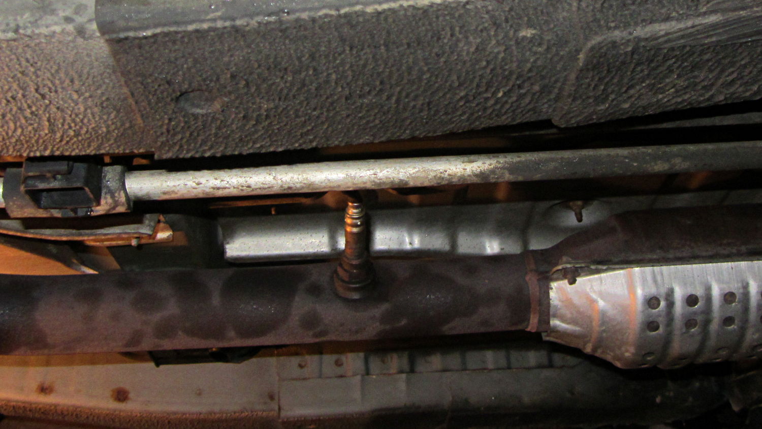
The sensor is relatively cheap (about $70 at the local Autozone) and, entirely unlike Bank 1 Sensor 1, readily accessible on the tailpipe downstream of the cat cracker:
Sienna Bank 1 Sensor 2 – in place
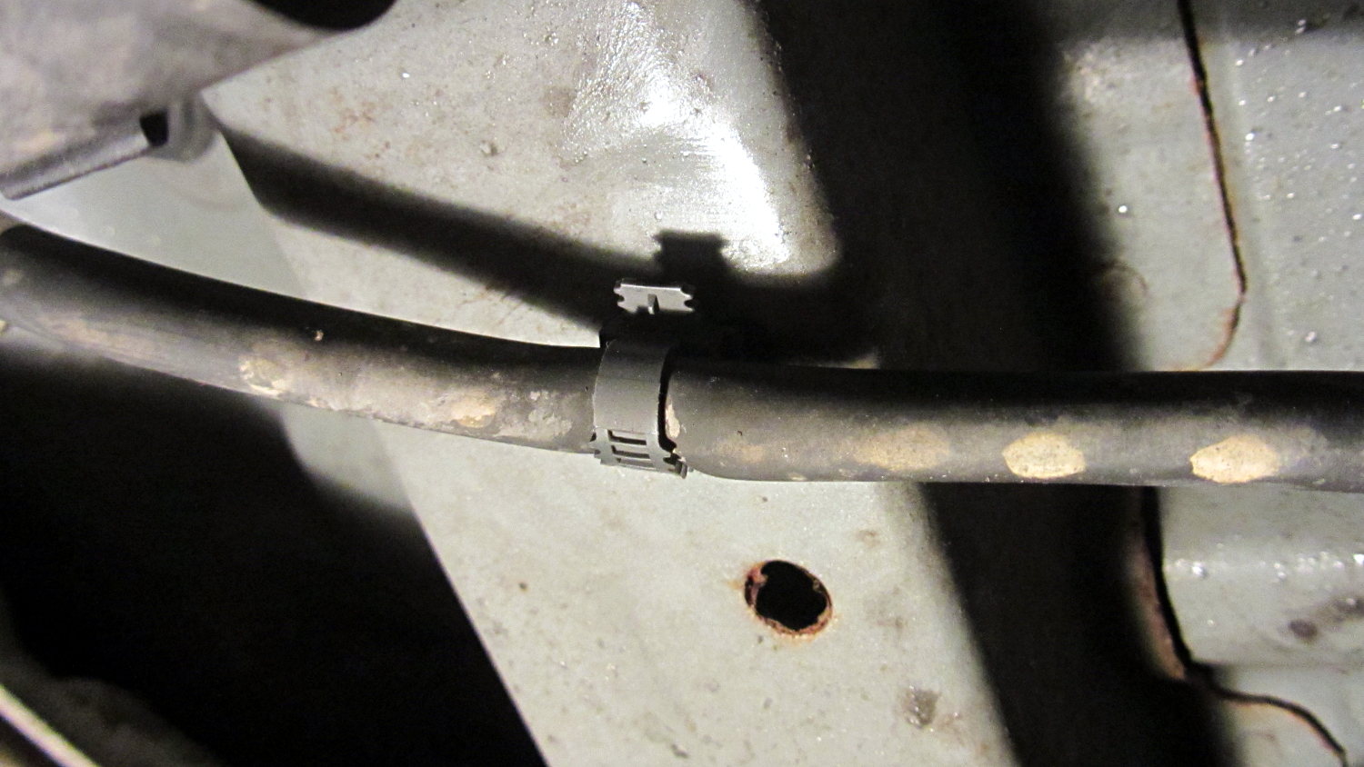
The OEM sensor cable runs in a sheath held to the chassis with a plastic clamp:
Sienna Bank 1 Sensor 2 – cable clamp
Jamming a small screwdriver into the clamp released the tongue and the sheath. The sheath vanishes into the van’s interior through a squishy rubber boot, with a crimped metal band joining the two:
Sienna Bank 1 Sensor 2 – floor boot
Internet lore would have you believe you can replace the sensor without removing the front passenger seat, but it’s much easier if you remove the four bolts, disconnect the seat sensor, and lay the seat on its back:
Sienna Bank 1 Sensor 2 – interior connector
More fiddly-diddly with the screwdriver under the van wrecked the band enough to separate sheath from boot, at which point deploying the BFW with the magic oxygen sensor socket showed that the anti-seize compound on the sensor’s thread worked as intended: after one oomph the sensor turned out by hand.
Then you just punch the boot through the floor and bring it all inside to splice new sensor onto OEM connector. Standardization is a wonderful thing; the sensor cable may use any one of eight color codes. The Toyota OEM sensor was a “Type B” that matches up with the Bosch replacement sensor thusly:
Heater = two black leads ↔ two white leads
Signal = blue lead ↔ black lead
Ground = white lead ↔ gray lead
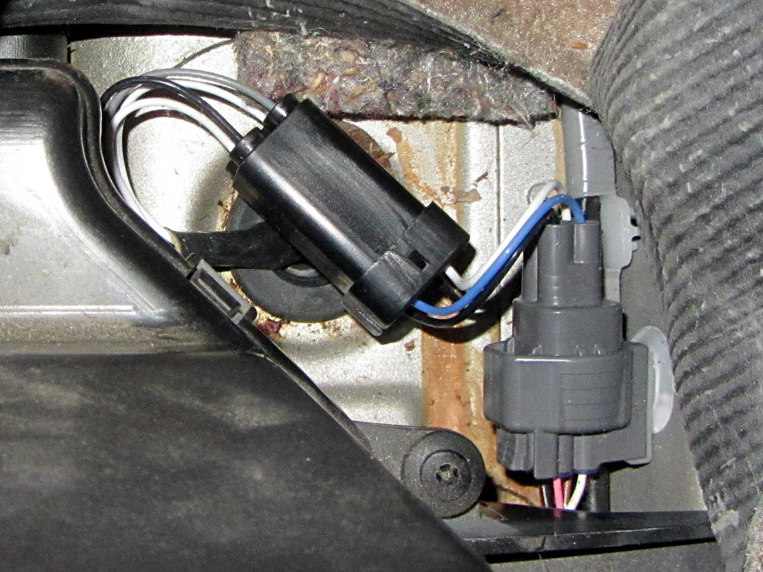
Although the splice block has water-resistant seals, I figured putting it inside the van couldn’t possibly be a Bad Idea, so there it is, nestled snugly into the recess in the floor:
Sienna Bank 1 Sensor 2 – splice block
Picked up a nice new Autel AL519OBD Code Scanner from the usual Amazon vendor, reset the trouble code, drove to-and-from Squidwrench (across the river, just barely far enough to reset the performance data), and so far it’s All Good. The motivation for getting my very own scanner, rather than returning to Autozone, is that the AL519 can do real-time graphing and data capture from various sensors, so I can perform Science! should the spirit move me.
The AL519 has a USB connection that appears as a USB serial device but, alas, the relentlessly Windows-centric host program won’t run under Wine.