The Smell of Molten Projects in the Morning

Ed Nisley's Blog: Shop notes, electronics, firmware, machinery, 3D printing, laser cuttery, and curiosities. Contents: 100% human thinking, 0% AI slop.

Category: Machine Shop

Mechanical widgetry

  • Browning Hi-Power Magazine Capacity Reduction Block: Steel Version

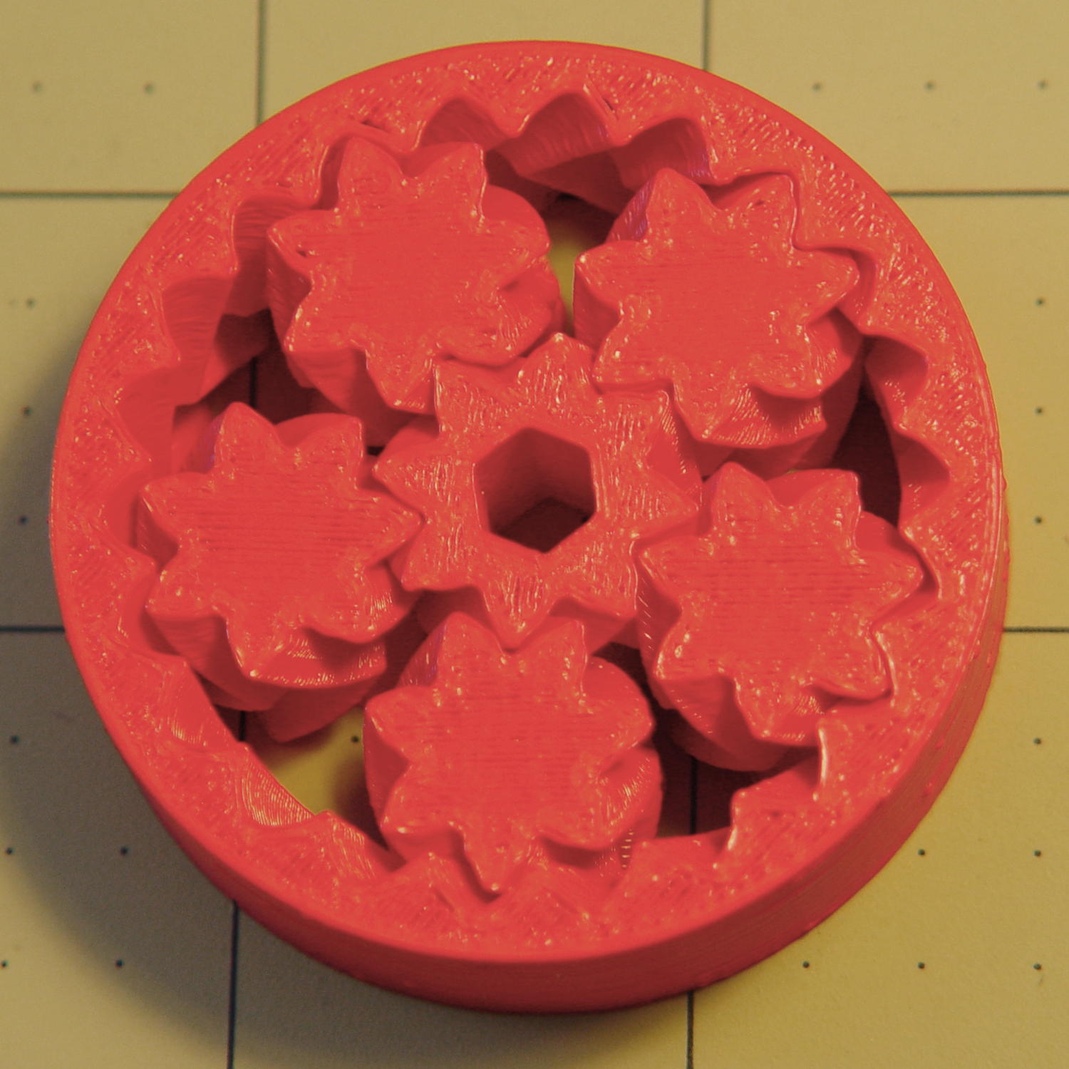
    The Shapeways stainless steel process produces nice results:

    Browning HP Mag Blocks - stainless and plastic - side
    Browning HP Mag Blocks – stainless and plastic – side

    It’s actually bronze-infused stainless steel powder, so it’s not exactly solid steel. The parts spend a day rattling around in a vibratory polisher that slightly rounds off their edges and smooths the surface, but (as with all 3D printed objects) you must learn to love the results; it’s certainly more photogenic than the black plastic version from my M2.

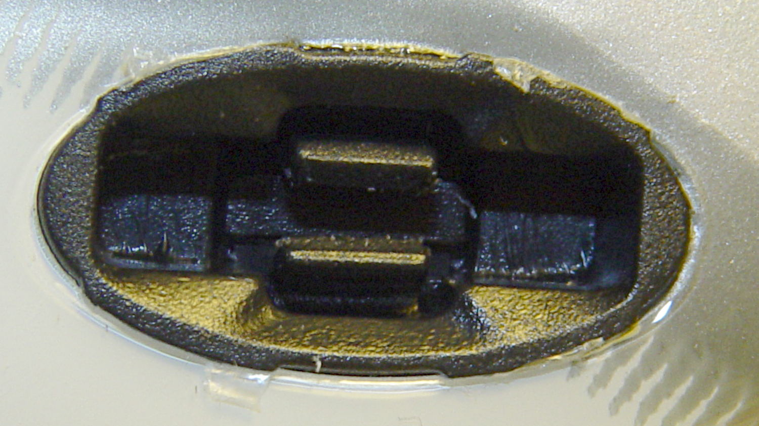
    The bottom view shows the hole I added to reduce the metallic volume; they charge a bit under $0.01/mm3, which encourages airy design:

    Browning HP Mag Blocks - stainless and plastic - bottom
    Browning HP Mag Blocks – stainless and plastic – bottom

    A cross-section view of the solid model shows the interior structure:

    Browning Hi-Power Magazine Block - steel - solid model - section
    Browning Hi-Power Magazine Block – steel – solid model – section

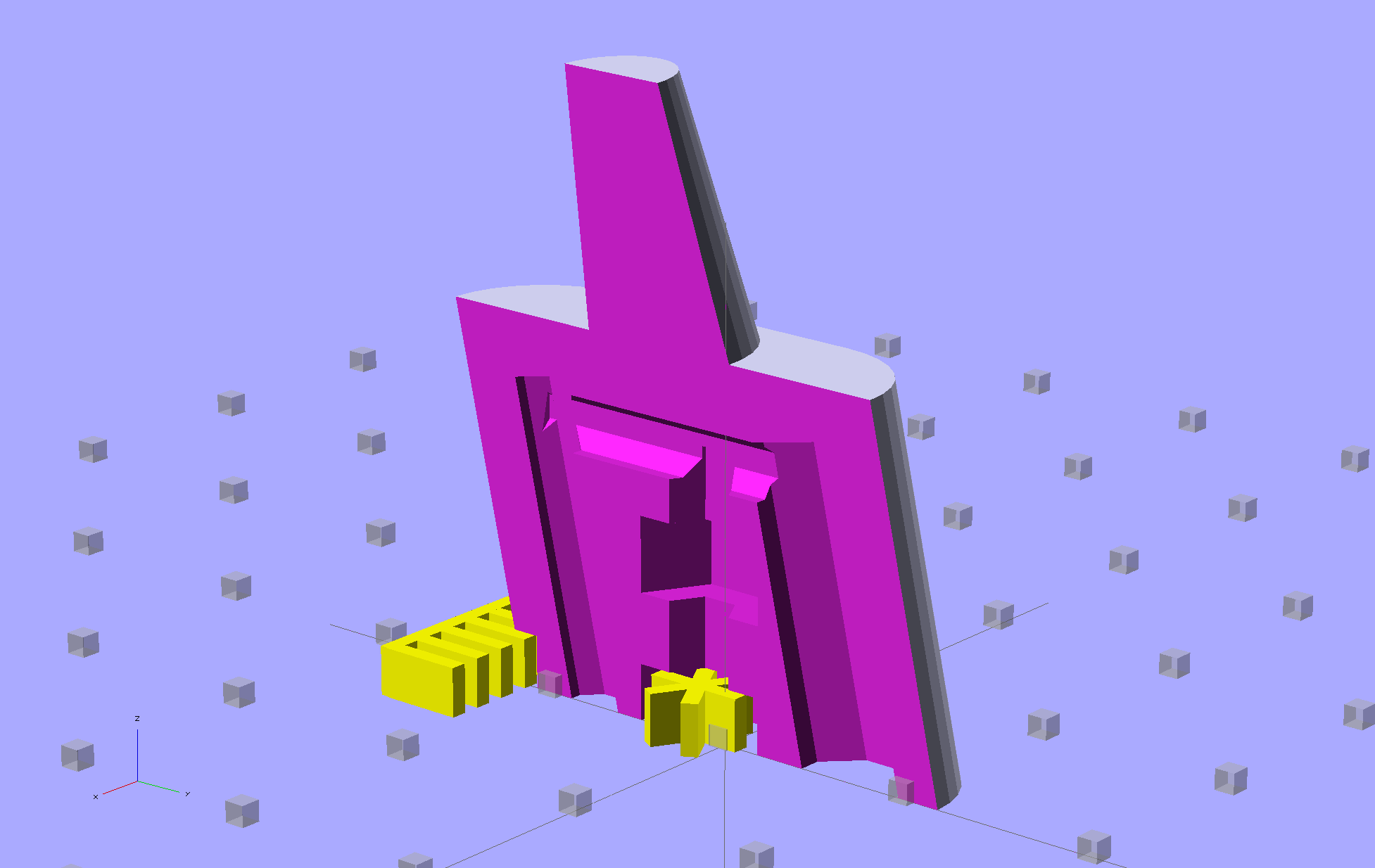
    The vent pipes are somewhat larger than in the plastic version and, obviously, I didn’t include the yellow support structures in the model I sent to Shapeways.

    Their specs give a minimum wall thickness of 3.0 mm, which I’m definitely pushing on some of the internal features. The pipes came out perfectly, as nearly as I can tell, although some polishing media did get wedged in the smaller hole. Air passes freely across the top, which is the important part.

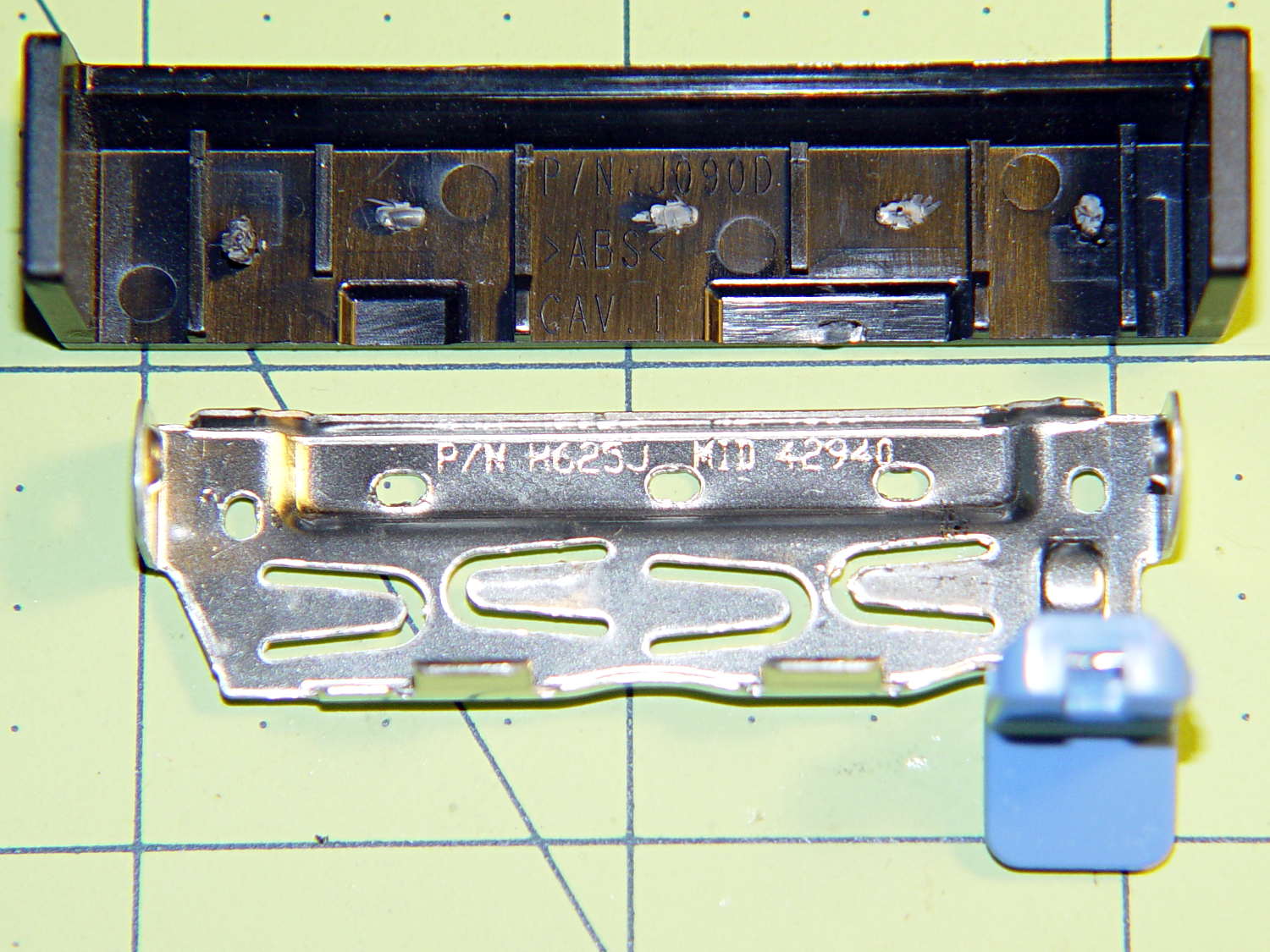
    Although the specs list a ±2 mm (!) tolerance, a comment in a Shapeways forum said that applies to larger objects, with 0.2 mm being typical for smaller objects. The steel and plastic parts match within 0.2 mm of the nominal model dimensions, so that lower tolerance seems about right; I have no idea how consistent it is.

    Another comment recommended carbide tools for secondary operations and that’s definitely true; I wrecked a perfectly good HSS tap trying to thread the central hole. Fortunately, I made the block slightly smaller outside and slightly larger inside, specifically to avoid having a deep thread; I intend to ram a standard M3x0.5 SHCS into that hole and epoxy it in place without worrying about thread damage.

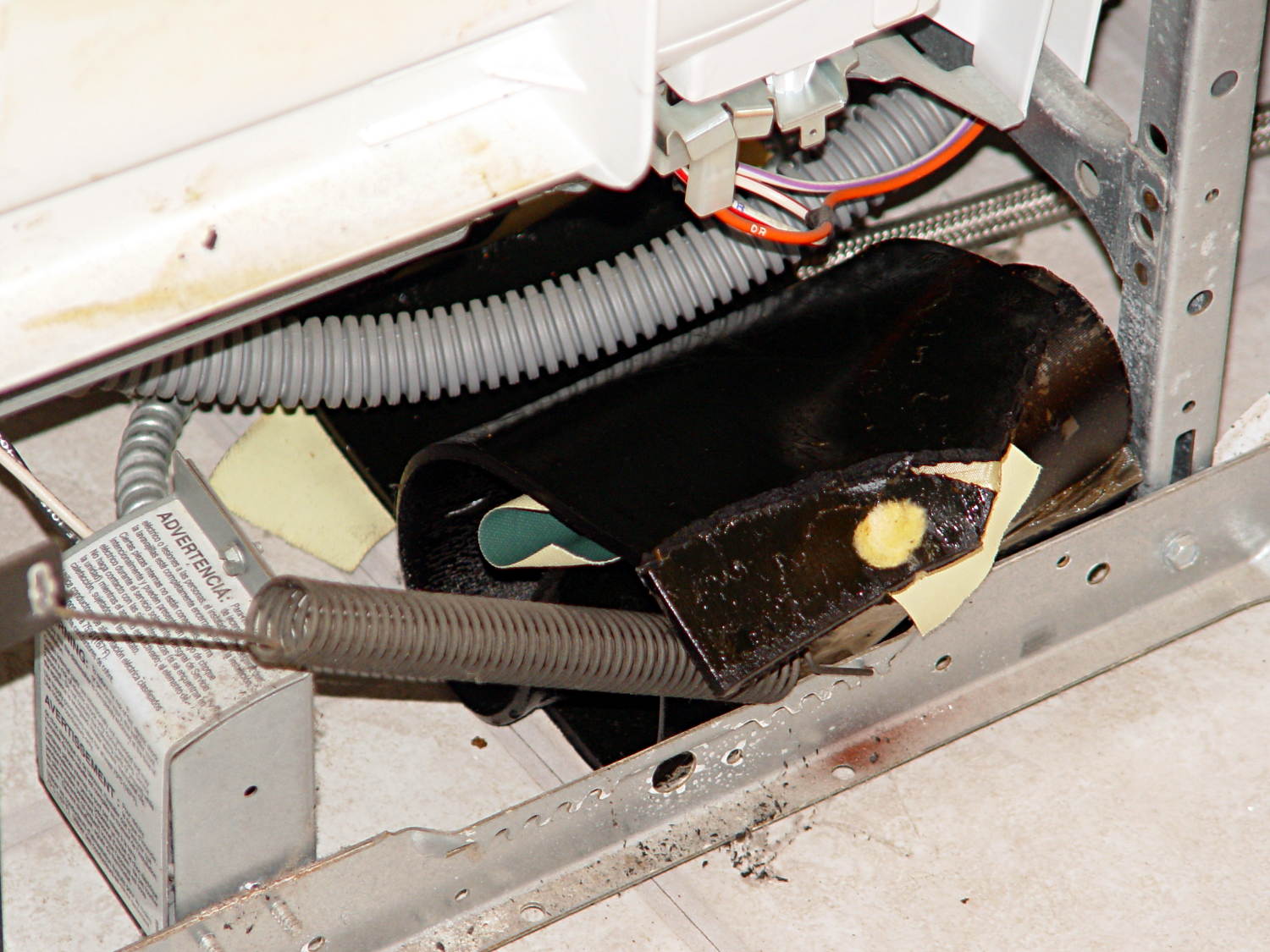
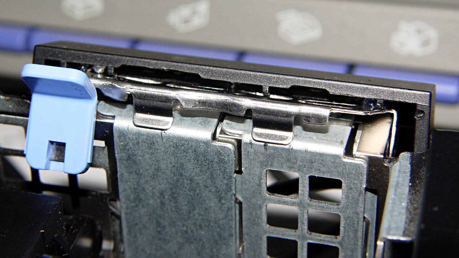
    A trial fit shows it captures the spring tab just like the plastic version did:

    Browning Hi-Power magazine - steel block trial fit
    Browning Hi-Power magazine – steel block trial fit

    I must contact my legislators again, as I’m pretty sure they’re not going to contact me.

    The OpenSCAD source code:

    // Browning Hi-Power Magazine Plug
    // Ed Nisley KE4ZNU December 2013
    
    Layout = "Show";			// Show Whole Split
    							//  Show = section view for demo, not for building
    							//  Whole = upright for steel or plastic
    							//  Split = laid flat for plastic show-n-tell assembly
    
    AlignPins = (Layout == "Split");					// pins only for plastic show-n-tell
    
    Support = true && (Layout != "Split");				// no support for split, optional otherwise
    
    //- Extrusion parameters must match reality!
    //  Print with 2 shells and 3 solid layers
    
    ThreadThick = 0.15;
    ThreadWidth = 0.40;
    
    HoleWindage = 0.2;
    
    Protrusion = 0.1;			// make holes end cleanly
    
    //----------------------
    // Dimensions
    
    Angle = 12.5;				// from vertical
    
    SpringID = 10.3;			// magazine spring curvature (measure with drill shank)
    SpringRadius = SpringID / 2;
    
    Length = 23.0;				// front-to-back perpendicular to magazine shaft
    Height = 18.0;				// bottom-to-top, parallel to magazine shaft
    							//  18 = 10 round max capacity
    
    RectLength = Length - SpringID;	// block length between end radii
    
    HornBaseOD = 8.0;			// fits between follower pegs to prevent shortening
    HornTipOD = 5.0;
    HornAddTip = (HornTipOD/2)*tan(Angle);
    HornAddBase = (HornBaseOD/2)*tan(Angle);
    HornAddLength = HornAddTip + HornAddBase + 2*Protrusion;
    HornLength = 12.0;			// should recompute ODs, but *eh*
    
    ScrewOD = 3.0 - 0.25;		// screw hole dia - minimal thread engagement
    ScrewLength = 13.0;
    ScrewOffset = -1.5;			//   ... from centerline
    							//  OEM = 0.0
    							//  generic A = -1.5
    
    NutOD = 5.6;				// hex nut dia across flats
    NutThick = 2.4;				//  ... generous allowance for nut
    NutTrapLength = 1.5*NutThick;		// allow for epoxy buildup
    NutOffset = 6.0;			//  ... base height from floor
    
    TrimHeight = 2.5;			// vertical clearance for spring clip on base plate
    							//   OEM = 2.5
    							//   generic A = 2.5
    
    TrimOffset = -9.5 + ScrewOffset;	// ... horizontal from centerline
    							//	 OEM = 0.0
    							//   generic A = 1.5
    
    SupportLength = 4.0;		// length of support struts under Trim
    SupportWidth = SpringID;	// ... width
    
    VentDia = 2.5;				// air vent from back of screw recess
    VentOffset = ScrewOffset - 6.0;
    
    RecessDia = 5.0;			// recess to reduce weight
    RecessLength = 0.66*Length;	//  ... internal length
    RecessOffset = 8.5;	//  ... offset from centerline
    
    PinOD = 1.72;				// alignment pins
    PinLength = 6.0;
    PinInset = 0.6*SpringRadius;	// from outside edges
    echo(str("Alignment pin length: ",PinLength));
    
    NumSides = 8*4;				// default cylinder sides
    
    Offset = 5.0/2;				// from centerline for build layout
    
    //----------------------
    // Useful routines
    
    function Delta(a,l) = l*tan(a);				// incremental length due to angle
    
    // Locating pin hole with glue recess
    //  Default length is two pin diameters on each side of the split
    
    module LocatingPin(Dia=PinOD,Len=0.0) {
    
    	PinLen = (Len != 0.0) ? Len : (4*Dia);
    
    	translate([0,0,-ThreadThick])
    		PolyCyl((Dia + 2*ThreadWidth),2*ThreadThick,4);
    
    	translate([0,0,-2*ThreadThick])
    		PolyCyl((Dia + 1*ThreadWidth),4*ThreadThick,4);
    
    	translate([0,0,-(Len/2 + ThreadThick)])
    		PolyCyl(Dia,(Len + 2*ThreadThick),4);
    
    }
    
    module PolyCyl(Dia,Height,ForceSides=0) {			// based on nophead's polyholes
    
      Sides = (ForceSides != 0) ? ForceSides : (ceil(Dia) + 2);
    
      FixDia = Dia / cos(180/Sides);
    
      cylinder(r=(FixDia + HoleWindage)/2,
               h=Height,
    	   $fn=Sides);
    }
    
    module ShowPegGrid(Space = 10.0,Size = 1.0) {
    
      Range = floor(50 / Space);
    
    	for (x=[-Range:Range])
    	  for (y=[-Range:Range])
    		translate([x*Space,y*Space,Size/2])
    		  %cube(Size,center=true);
    
    }
    
    //----------------------
    // The magazine block
    
    module Block(SectionSelect = 0) {
    
    CropHeight = Height*cos(Angle);				// block height perpendicular to base
    echo(str("Perpendicular height: ",CropHeight));
    
    	difference() {
    		union() {
    			intersection() {
    				rotate([Angle,0,0])
    					hull() {
    						for (i=[-1,1])
    							translate([0,i*RectLength/2,-((Length/2)*sin(Angle) + Protrusion)])						cylinder(r=SpringRadius,
    										h=(Height + 2*(Length/2)*sin(Angle) + 2*Protrusion),
    										$fn=NumSides);
    					}
    				translate([0,0,CropHeight/2])
    					cube([2*SpringID,3*Length,CropHeight],center=true);
    			}
    			translate([0,-Height*sin(Angle),Height*cos(Angle)])
    				resize([SpringID,0,0])
    					intersection() {
    						rotate([Angle,0,0])
    							translate([0,0,-(HornAddBase + Protrusion)])
    								cylinder(r1=HornBaseOD/2,
    										r2=HornTipOD/2,
    										h=(HornLength + HornAddLength + Protrusion),
    										$fn=NumSides);
    					cube([2*SpringID,Length,2*(HornLength*cos(Angle) + Protrusion)],center=true);
    				}
    		}
    
    		translate([0,ScrewOffset,-Protrusion])		// screw
    			rotate(180/6)
    				PolyCyl(ScrewOD,(ScrewLength + Protrusion),6);
    
    		translate([0,ScrewOffset,NutOffset])		// nut trap in center
    			rotate(180/6)
    				PolyCyl(NutOD,NutTrapLength,6);
    
    		translate([0,ScrewOffset,-Protrusion])		// nut clearance at base
    			rotate(180/6)
    				PolyCyl(NutOD,(1.1*NutThick + Protrusion),6);
    
    		translate([SpringID/2,TrimOffset,-Protrusion])
    			rotate(180)
    				cube([SpringID,Length,(TrimHeight + Protrusion)],center=false);
    
    		if (AlignPins)								// alignment pins
    			for (i=[-1,1])
    				rotate([Angle,0,0])
    				translate([0,
    							(i*((Length/2)*cos(Angle) - PinInset)),
    							(CropHeight/2 - i*2*PinInset)])
    					rotate([0,90,0]) rotate(45 - Angle)
    						LocatingPin(PinOD,PinLength);
    
    		translate([0,(ScrewOffset + 1.25*NutOD),ScrewLength])	// air vent
    			rotate([90,0,0]) rotate(180/8)
    				PolyCyl(VentDia,3*NutOD,8);
    		translate([0,VentOffset,-(VentDia/2)*tan(Angle)])
    			rotate([Angle,0,0]) rotate(180/8)
    				PolyCyl(VentDia,(RecessLength + (VentDia/2)*tan(Angle)),8);
    
    		translate([0,(RecessOffset + ScrewOffset),0])			// weight reduction recess
    			rotate([Angle,0,0]) rotate(180/8)
    				translate([0,0,-((RecessDia/2)*tan(Angle))])
    				PolyCyl(RecessDia,(RecessLength + (RecessDia/2)*tan(Angle)),8);
    
    		if (SectionSelect == 1)
    			translate([0*SpringID,-2*Length,-Protrusion])
    				cube([2*SpringID,4*Length,(Height + HornLength + 2*Protrusion)],center=false);
    		else if (SectionSelect == -1)
    			translate([-2*SpringID,-2*Length,-Protrusion])
    				cube([2*SpringID,4*Length,(Height + HornLength + 2*Protrusion)],center=false);
    	}
    
    SupportBars = floor((SupportWidth/2) / (4*ThreadWidth));
    
    	if (Support) {									// add support structures
    		for (i = [-SupportBars:SupportBars])
    			translate([i*4*ThreadWidth,
    					   (TrimOffset - SupportLength/2 - ThreadWidth),
    					   (TrimHeight - ThreadThick)/2])
    				color("Yellow")
    				cube([(2*ThreadWidth),SupportLength,(TrimHeight - ThreadThick)],center=true);
    
    		translate([0,(TrimOffset - SupportLength - ThreadWidth),(TrimHeight - ThreadThick)/2])
    			color("Yellow")
    			cube([SupportWidth,(2*ThreadWidth),(TrimHeight - ThreadThick)],center=true);
    
    		translate([0,ScrewOffset,0])
    			for (j=[0:5]) {
    			rotate(30 + 360*j/6)
    				translate([(NutOD/2 - ThreadWidth)/2,0,(1.1*NutThick - ThreadThick)/2])
    					color("Yellow")
    					cube([(NutOD/2 - ThreadWidth),
    						  (2*ThreadWidth),
    						  (1.1*NutThick - ThreadThick)],
    						  center=true);
            }
    	}
    
    }
    
    //-------------------
    // Build it...
    
    ShowPegGrid();
    
    if (Layout == "Show")
    	Block(1);
    
    if (Layout == "Whole")
    	Block(0);
    
    if (Layout ==  "Split") {
    	translate([(Offset + Length/2),Height/2,0])
    		rotate(90) rotate([0,-90,-Angle])
    			Block(-1);
    	translate([-(Offset + Length/2),Height/2,0])
    		rotate(-90) rotate([0,90,Angle])
    			Block(1);
    }
    
  • Sandisk 32 GB Flash Drive: Now With String!

    So I drill two holes in the dust caps of those teensy Sandisk drives and added a cheerful red string:

    Sandisk 32 GB Flash Drive - cap string
    Sandisk 32 GB Flash Drive – cap string

    That this should not be necessary goes without saying…

  • Kenmore Dishwasher Sound Deadening Sheets: Slip Sliding Away, Redux

    The springs balancing the dishwasher door started twanging again, which I now know is the diagnostic sign that an asphalt sound deadening sheet has slipped off the tub. A sheet on the right side almost perpetrated a clean escape, but the flap drooping over the spring gave it away:

    Dishwasher sound deadener - slipped away
    Dishwasher sound deadener – slipped away

    Another sheet on the left side was inching away, but hadn’t quite gotten over the fence:

    Dishwasher sound deadener - slipping away
    Dishwasher sound deadener – slipping away

    They’re pretty much a rigid solid at room temperature:

    Dishwasher sound deadener - wrinkled asphalt sheet
    Dishwasher sound deadener – wrinkled asphalt sheet

    It puts one in mind of the pitch drop experiments now running in various labs. In this case, we now know it takes about four years for an asphalt sheet to slide completely off the tub; those two sheets were definitely in place when I buttoned it up after the previous one broke free.

    I applied a heat gun to soften the sheets, then smoothed them around the tub again. This time I applied long strips of Gorilla Tape from one side to the other, rather than short strips of ordinary duct tape along the edges, and maybe this fix will outlast either the dishwasher or our tenure here, whichever comes first…

  • Planetary Gear Bearing: Now With Knurling!

    OK, I couldn’t resist. Tweaking a few lines of code wrapped a knurl around emmitt’s Gear Bearing for enhanced griptivity:

    Knurled vs original Planetary Gear Bearing
    Knurled vs original Planetary Gear Bearing

    That image has desaturated red to suppress the camera’s red burnout. It looks better in the realm of pure math:

    Planetary Gear Bearing - Kurled - solid model
    Planetary Gear Bearing – Kurled – solid model

    Reducing the tolerance parameter to 0.4 produced a surprisingly rigid, yet freely turning, bearing that required no cleanup: it popped off the plate ready to roll!

    The heavy lifting in the OpenSCAD source code remains emmitt’s work. I replaced the outer cylinder with a knurl and simplified his monogram to stand out better amid the diamonds. This is the affected section:

    ... snippage ...
    translate([0,0,T/2]){
    	difference(){
    //		cylinder(r=D/2,h=T,center=true,$fn=100);
    		render(convexity=10)
    		translate([0,0,-T/2])
    			knurl(k_cyl_hg=T,
    			k_cyl_od=D,
    			knurl_wd=5.0,
    			knurl_hg=5.0,
    			knurl_dp=0.5,
    			e_smooth=5.0/2);
    		herringbone(nr,pitch,P,DR,-tol,helix_angle,T+0.2);
    //		difference(){
    			translate([0,-(D/2+4.5),0])rotate([90,0,0])monogram(h=10);
    //			cylinder(r=D/2-0.25,h=T+2,center=true,$fn=100);
    //		}
    	}
    	rotate([0,0,(np+1)*180/ns+phi*(ns+np)*2/ns])
    	difference(){
    		mirror([0,1,0])
    			herringbone(ns,pitch,P,DR,tol,helix_angle,T);
    		cylinder(r=w/sqrt(3),h=T+1,center=true,$fn=6);
    	}
    	for(i=[1:m])rotate([0,0,i*360/m+phi])translate([pitchD/2*(ns+np)/nr,0,0])
    		rotate([0,0,i*ns/m*360/np-phi*(ns+np)/np-phi])
    			render(convexity=10)
    			herringbone(np,pitch,P,DR,tol,helix_angle,T);
    }
    

    I also added a few render(convexity=n) operations to improve the preview, but that’s just cosmetic.

  • Bell Helmet Visor Mount Tabs

    Santa delivered a pair of helmets that will require mirror mounts and a mic boom before the spring riding season kicks in. The visor has tabs that snap into sockets on each side of the helmet:

    Bell Helmet Visor Mount - socket
    Bell Helmet Visor Mount – socket

    It occurred to me that I could make an interposer between the helmet and the visor that could anchor the mic boom, with a tab for the helmet and a socket of some sort for the visor. While that’s still on the to-do list, the tab looks like this:

    Bell Helmet Visor Mount
    Bell Helmet Visor Mount

    Those are 1 mm cubes on 10 mm centers, so this is a teeny little thing.

    I don’t have a good idea for the corresponding socket, because those little grippers seem much too small for 3D printing, but now I have some tabs to play with:

    Bell Helmet Visor Mount - OEM vs 3D Printed
    Bell Helmet Visor Mount – OEM vs 3D Printed

    The OpenSCAD source code puts the tab atop an oval base plate, but it’ll eventually stick out of the boom mount:

    // Bell Helmet Visor Mount
    // Ed Nisley KE4ZNU
    // December 2013
    
    // Layout options
    
    Layout = "Build";			// Build Show
    
    //-----
    // Extrusion parameters must match reality!
    
    ThreadThick = 0.20;
    ThreadWidth = 0.4;
    
    HoleWindage = 0.2;
    
    //-- Handy stuff
    
    function IntegerMultiple(Size,Unit) = Unit * ceil(Size / Unit);
    
    Protrusion = 0.1;			// make holes end cleanly
    
    inch = 25.4;
    
    //----------------------
    // Dimensions
    
    //----------------------
    // Useful routines
    
    module PolyCyl(Dia,Height,ForceSides=0) {			// based on nophead's polyholes
    
      Sides = (ForceSides != 0) ? ForceSides : (ceil(Dia) + 2);
    
      FixDia = Dia / cos(180/Sides);
    
      cylinder(r=(FixDia + HoleWindage)/2,
               h=Height,
    	   $fn=Sides);
    }
    
    //- Put peg grid on build surface
    
    module ShowPegGrid(Space = 10.0,Size = 1.0) {
    
    	RangeX = floor(100 / Space);
    	RangeY = floor(125 / Space);
    
    	for (x=[-RangeX:RangeX])
    		for (y=[-RangeY:RangeY])
    			translate([x*Space,y*Space,Size/2])
    			%cube(Size,center=true);
    
    }
    
    //-------------------
    // Shapes
    
    TabBaseLength = 17.0;
    TabTopLength = 15.5;
    
    TabWidth = 4.00;
    TabHeight = 5.5;
    TabEmbed = 0.5;
    TabTaperHeight = 3.70;
    TabBaseHeight = TabHeight - TabTaperHeight;
    
    LatchBar = 2.25;					// square cross section
    WebIndent = 1.60;					// from outside edge of post
    WebThick = TabWidth - 2*WebIndent;
    LatchIndentTall = TabHeight - LatchBar;
    
    PostLength = 5.00;
    PostTaper = 1.25;
    LatchIndentLength = TabBaseLength - 2*(PostLength + PostTaper);
    
    module BellLatch() {
    
    	difference() {
    		intersection() {
    			translate([0,TabWidth/2,0]) rotate([90,0,0])				// side view
    			linear_extrude(height=TabWidth)
    				polygon(points=[
    					[-TabBaseLength/2,-TabEmbed],[-TabBaseLength/2,TabBaseHeight],[-TabTopLength/2,TabHeight],
    					[TabTopLength/2,TabHeight],[TabBaseLength/2,TabBaseHeight],[TabBaseLength/2,-TabEmbed]
    				]);
    
    			translate([0,0,-TabEmbed])
    			linear_extrude(height=(TabHeight + TabEmbed),convexity=3)				// top view
    				polygon(points=[
    					[-TabBaseLength/2,-TabWidth/2],
    					[-TabBaseLength/2, TabWidth/2],
    					[-(TabBaseLength/2 - PostLength), TabWidth/2],
    					[-(TabBaseLength/2 - PostLength - PostTaper),LatchBar/2],
    					[ (TabBaseLength/2 - PostLength - PostTaper),LatchBar/2],
    					[ (TabBaseLength/2 - PostLength),TabWidth/2],
    					[ TabBaseLength/2, TabWidth/2],
    					[ TabBaseLength/2,-TabWidth/2],
    					[ (TabBaseLength/2 - PostLength),-TabWidth/2],
    					[ (TabBaseLength/2 - PostLength - PostTaper),-LatchBar/2],
    					[-(TabBaseLength/2 - PostLength - PostTaper),-LatchBar/2],
    					[-(TabBaseLength/2 - PostLength),-TabWidth/2]
    				]);
    		}
    		for (y=[-1,1])
    		translate([0,y*((TabWidth/2 + WebThick/2)),LatchIndentTall/2])
    			cube([LatchIndentLength,TabWidth,LatchIndentTall],center=true);
    	}
    
    /*	difference() {
    		translate([0,0,TabHeight/2])
    		cube([TabLength,TabWidth,TabHeight],center=true);
    	}
    */
    }
    
    //-------------------
    // Build things...
    
    ShowPegGrid();
    
    if (Layout == "Show")
    	BellLatch();
    
    if (Layout == "Build") {
    	translate([0,0,2.0])
    		BellLatch();
    	difference() {
    		resize([20.0,10.5,2.0])
    			cylinder(r=2,h=2,$fn=32);
    		for (x=[-1,1])
    			translate([x*(5/2 + TabBaseLength/2 + 0.5),0,5+0.6])
    				cube([5,25,10],center=true);
    	}
    
    }
    
  • Planetary Gear Bearing

    Most of the things I design don’t have moving parts, so I printed emmitt’s Gear Bearing as a fondletoy:

    Planetary Gear Bearing
    Planetary Gear Bearing

    Setting the clearance to 0.5 produced a free fit with absolutely no cleanup or run-in required; the center hole is a sliding fit for a 6 mm hex wrench.

    I should do another one with knurling around the outside…

    The picture has strongly desaturated reds, which reveals the top surface a bit more clearly.

  • Optiplex 980 PCI Card Clamp Cover Repair

    The new-to-me Optiplex 980 has a tool-free clamp securing the PCI card brackets to the chassis, with a nice plastic dress cover that really finishes off that side of the case. Alas, it’s secured by five small heat-staked plastic pegs that I managed to shear off as part of a finger fumble that you’ll recognize when it happens to you and which I need not further discuss:

    Optiplex 980 PCI Clamp Cover - disassembled
    Optiplex 980 PCI Clamp Cover – disassembled

    So I drilled two slightly undersized holes for the tiniest screws in the Little Box o’ Tiny Screws:

    Optiplex 980 PCI Clamp Cover - drilling
    Optiplex 980 PCI Clamp Cover – drilling

    The two end plates sticking up are the only square parts of the cover, so that thing is actually clamped by the right-side plate and sheer will power. I ran the drill down 3 mm from the top of the post at the slowest manual jog speed from the Joggy Thing and I did not break through the top and did not hit that lathe bit under the cover.

    The screw threads and a dab of epoxy hold them in place:

    Optiplex 980 PCI Clamp Cover - tiny screws
    Optiplex 980 PCI Clamp Cover – tiny screws

    I’d like to say the finished repair looked like this:

    Optiplex 980 PCI Clamp Cover - in place
    Optiplex 980 PCI Clamp Cover – in place

    But, alas, the eagle-eyed reader will note that the screws are gone, replaced by two dabs of clear acrylic caulk; those faint threads and epoxy were no match for the snap of that latching lever and the slight distortion caused by the spring fingers applying force to the brackets.

    Ah, well, it’s close enough…