Ed Nisley's Blog: Shop notes, electronics, firmware, machinery, 3D printing, laser cuttery, and curiosities. Contents: 100% human thinking, 0% AI slop.
I did a lightning talk / show-n-tell last Tuesday at the MHV LUG meeting and covered one end of a table with the Neopixel-lit bulbs & vacuum tubes & hard drive platters I’ve been playing with:
The ceramic ring screws down around the socket shell and pulls it up against the base; the threads have only as much precision as required to keep it from falling off. I may need to add a leveling shim just so I don’t have to explain why it’s always crooked.
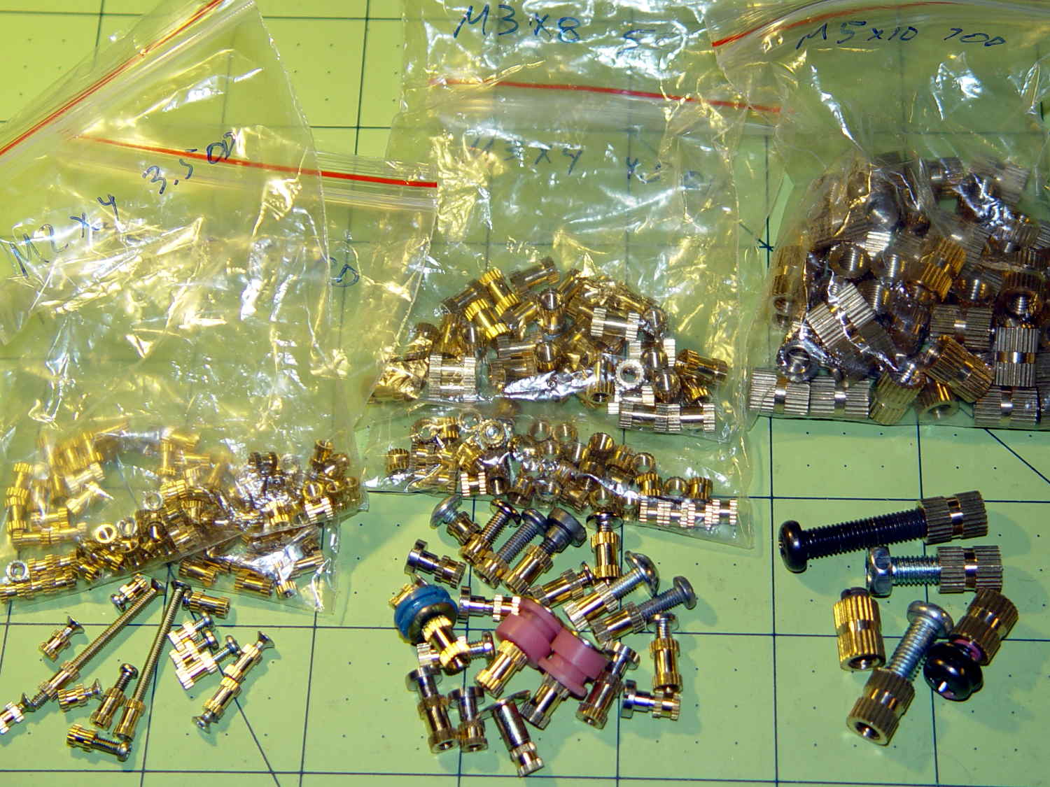
These seem like they ought to come in handy for fastening things to 3D printed objects:
Kurled Inserts – M2 M3 M5
The assorted screws come from the Small Can o’ Small Screwlike Things, all harvested from various dead bits of consumer electronics:
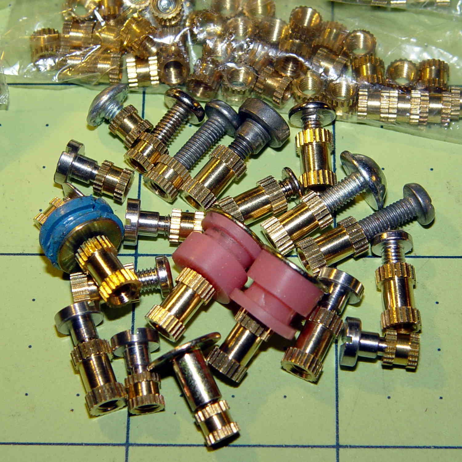
Kurled M3 Inserts
These would benefit from a heated staking tool that slides them into the hole parallel to the axis and flush with the surface. Such things are commercially available, of course, but for my simple needs something involving a cartridge heater, a wall wart, and a drill press may suffice.
It would be better if the inserts had actual knurls, rather than splines. So it goes.
For the record (thread x length x Knurl OD x Body OD):
M2 x 4 x 3.5 x 2.8
M2 x 6 x 3.5 x 2.7
M3 x 4 x 4.5 x 3.8
M3 x 8 x 5.0 x 3.9
M5 x 10 x 7.5 x 6.9
The actual measurements seem to vary within ±0.02 of nominal and I doubt the manufacturing consistency justifies any assumption tighter than ±0.1 mm.
The M3 inserts really do have two different ODs.
The M5 insert was listed as “7 mm OD” and measures 7.5 mm, which suggests a typo in the description.
So an ordinary cylinder() with the nominal knurl OD or a PolyCyl() with the nominal body OD should suffice. Horizontal holes can probably use a plain old cylinder() with the nominal body OD, because they need reaming anyway.
Perhaps a dab of epoxy would bond better with the plastic around a nominal-size hole than forcing the insert into an undersized hole or heat-bonding the insert. Some experimentation is in order.
Ten bucks for the entire collection (five bags of 50 inserts each = 250 little brass doodads = 4¢ each), shipped free halfway around the planet, seemed reasonable, given that inch size knurled brass inserts run anywhere from 50¢ to upwards of $2 a pop and a Genuine Helicoil 4-40 insert sets you back just shy of a buck.
An Amazon vendor offers 4-40 inserts for $0.24 each in single quantities, but with $9.25 shipping. [le sigh]
Inch-size inserts with knurled rings intended for ultrasonic bonding seem to be 5¢ to 15¢ on eBay. I think the straight-side versions will work better than the tapered ones for heat or epoxy bonding.
It knurls my knuckles that we here in the US haven’t gone solidly metric. Yes, I have a goodly assortment of metric hardware in addition to the harvested fasteners shown above, but it definitely wasn’t cheap & readily available.
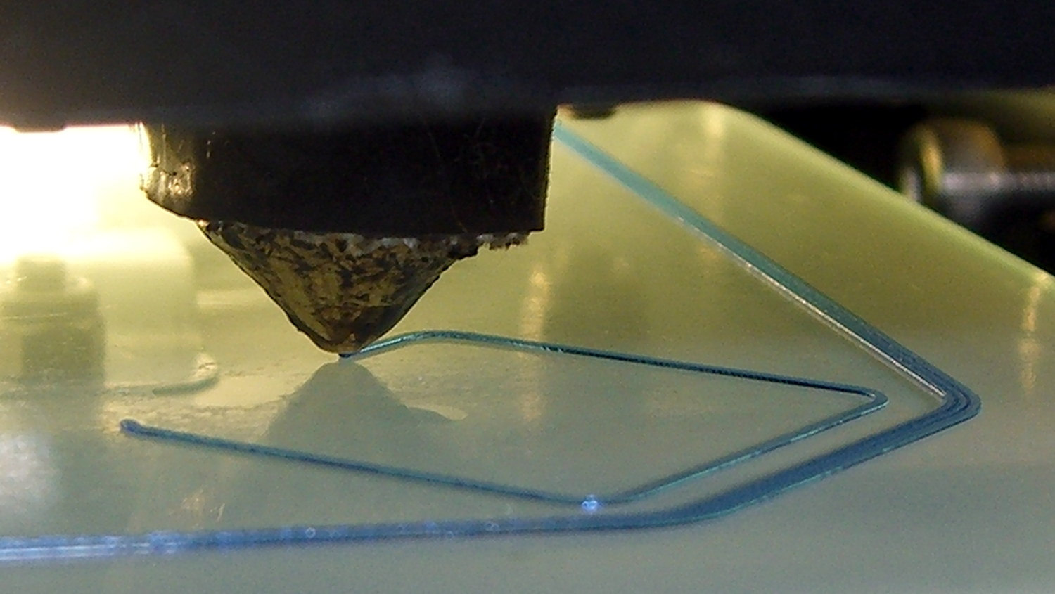
So, while printing the first pass of the halogen lamp base, this happened:
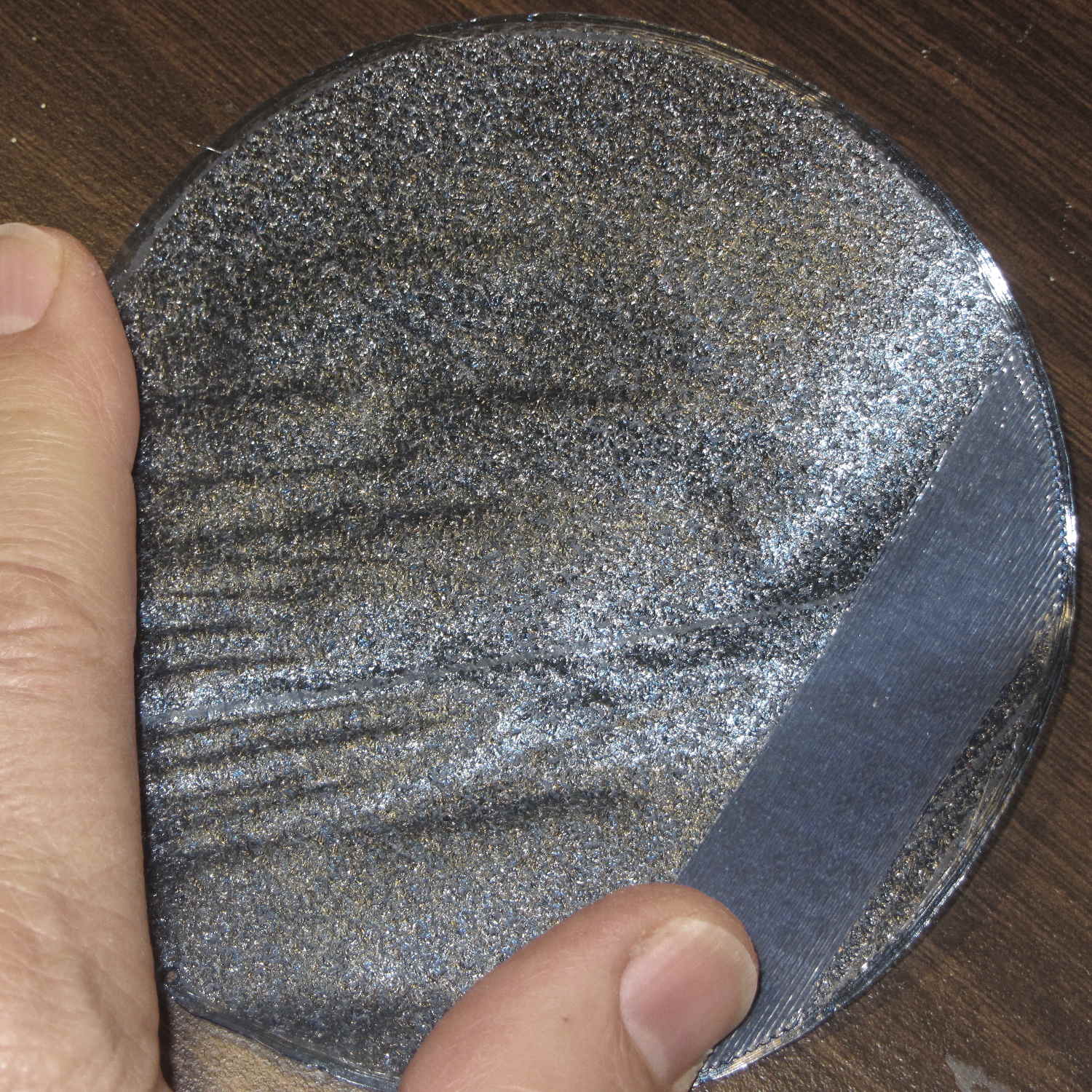
Lamp Base – wrecked print
The first layer went down fine, but the filament stopped feeding after laying down the small linear patch along the right side. The wrinkles come from me peeling it off the platform while it was still hot and flexy.
Although feeding PETG at 75 mm/s for infill worked so far (I mean, sheesh, look at all the stuff I’ve made in the last year), this involved a fairly large expanse of filament and maybe, just maybe, the high flow rate cooled the nozzle enough to increase the extrusion pressure and eventually strip the filament.
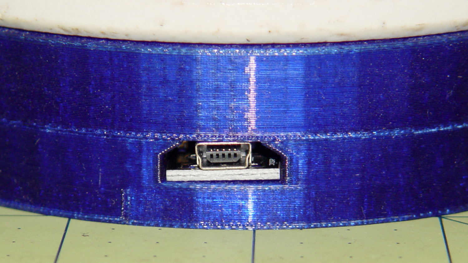
I shoved the filament hard enough to get it feeding again, bumped the extrusion temperature to 260 °C and started another print, whereupon things went swimmingly for the first 12.2 mm. Alas, the filament jammed again, just below the top of the hole for the USB adapter, where you see the odd line in the middle of the finished base:
Lamp Base – USB port
Because it’s now printing a relatively thin cylinder at relatively slow speeds (less infill per perimeter), the “feeding too fast” argument falls flat on its face: obviously, something else is wrong.
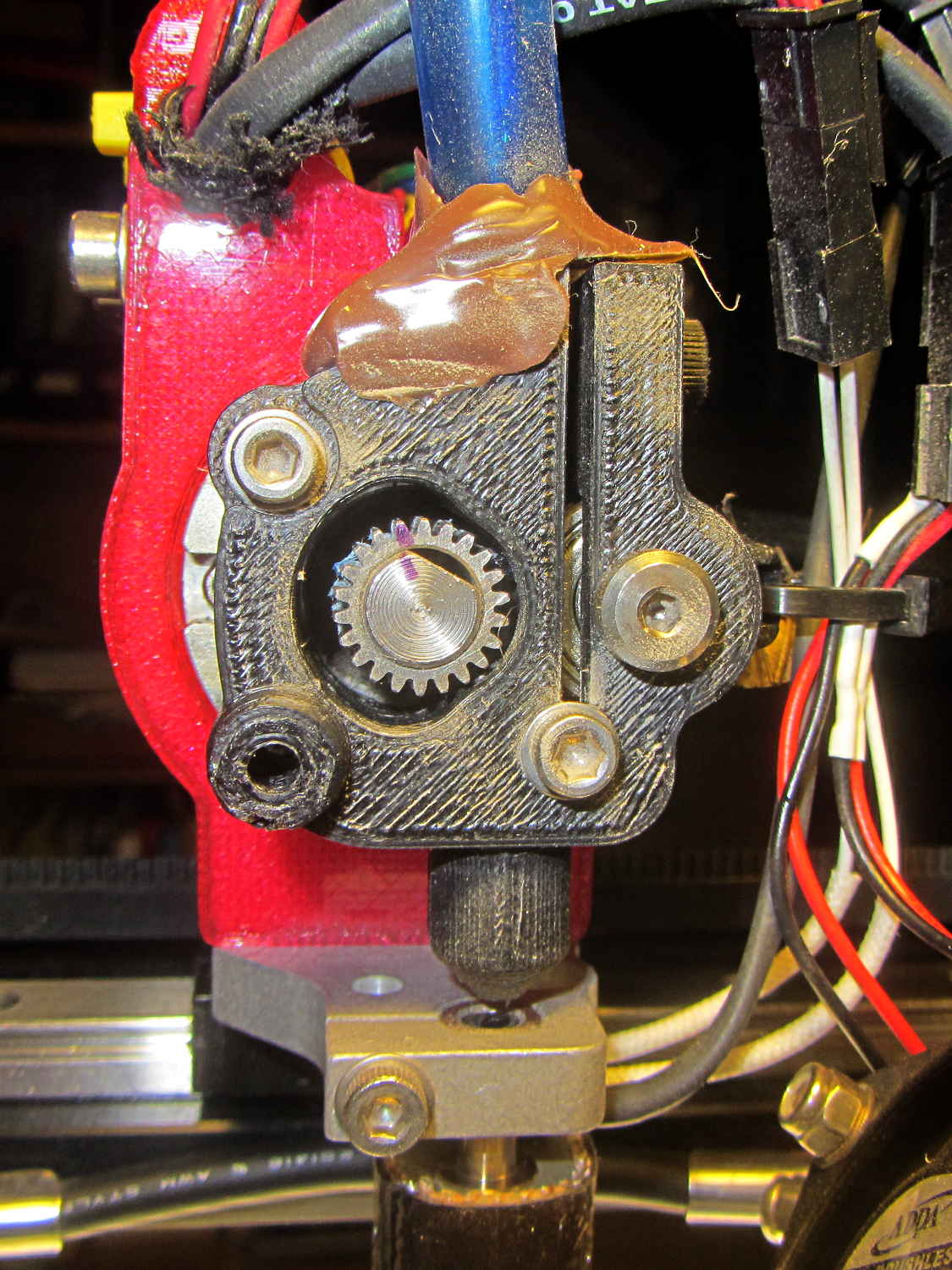
Removing the fans showed a bit of plastic on the drive gear teeth, but nothing too terrible:
M2 Filament Drive – jam front view
The witness mark on the planetary gearbox output shaft still lines up with the mark on the gear, so the tiny grub screw hasn’t come loose. Note the slight misalignment between the bottom of the filament drive and the hot end inlet; I’ve already snipped the filament and done some retraction.
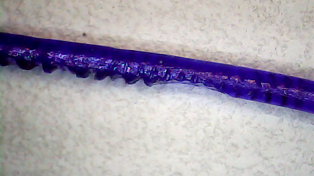
A small struggle involving needle nose pliers dragged this classic gouged filament from the drive:
Stripped PETG Filament
This spool of PETG filament started out at 1.70 mm, but this section measures 1.80 mm. That’s at the high end of the ±0.05 mm tolerance around the nominal 1.75 mm, but, frankly, I don’t take the tolerance too seriously.
Undamaged filament from the spool didn’t push smoothly through the drive, so I reamed out the entire path with a 2 mm drill (actually, a #46 drill = 2.05 mm). I don’t recall if I did that before mounting the drive, but even if I did, I’d expect some crud and distortion to accumulate after a while; it’s been running without much attention since last March.
Reassembling the drive and feeding the filament to just above the hot end showed a slight misalignment:
M2 Filament Dive – misaligned front view
I cured that by loosening the screws and rotating the whole drive slightly clockwise:
M2 Filament Dive – realigned front view
Viewed from the side, the drive positions the filament slightly too far to the rear:
M2 Filament Dive – alignment side view
I didn’t (think to) check if the hole in the snout has become bellmouthed, but it wouldn’t take much. In any event, the filament fed into the hot end without incident, so maybe there’s enough slop to cover that misalignment. Maybe I should add a small shim behind the drive?
With the filament drive working again, I had Slic3r chop the bottom off the solid model of the lamp base and create the G-Code for just the top section, which printed without any problem at all.
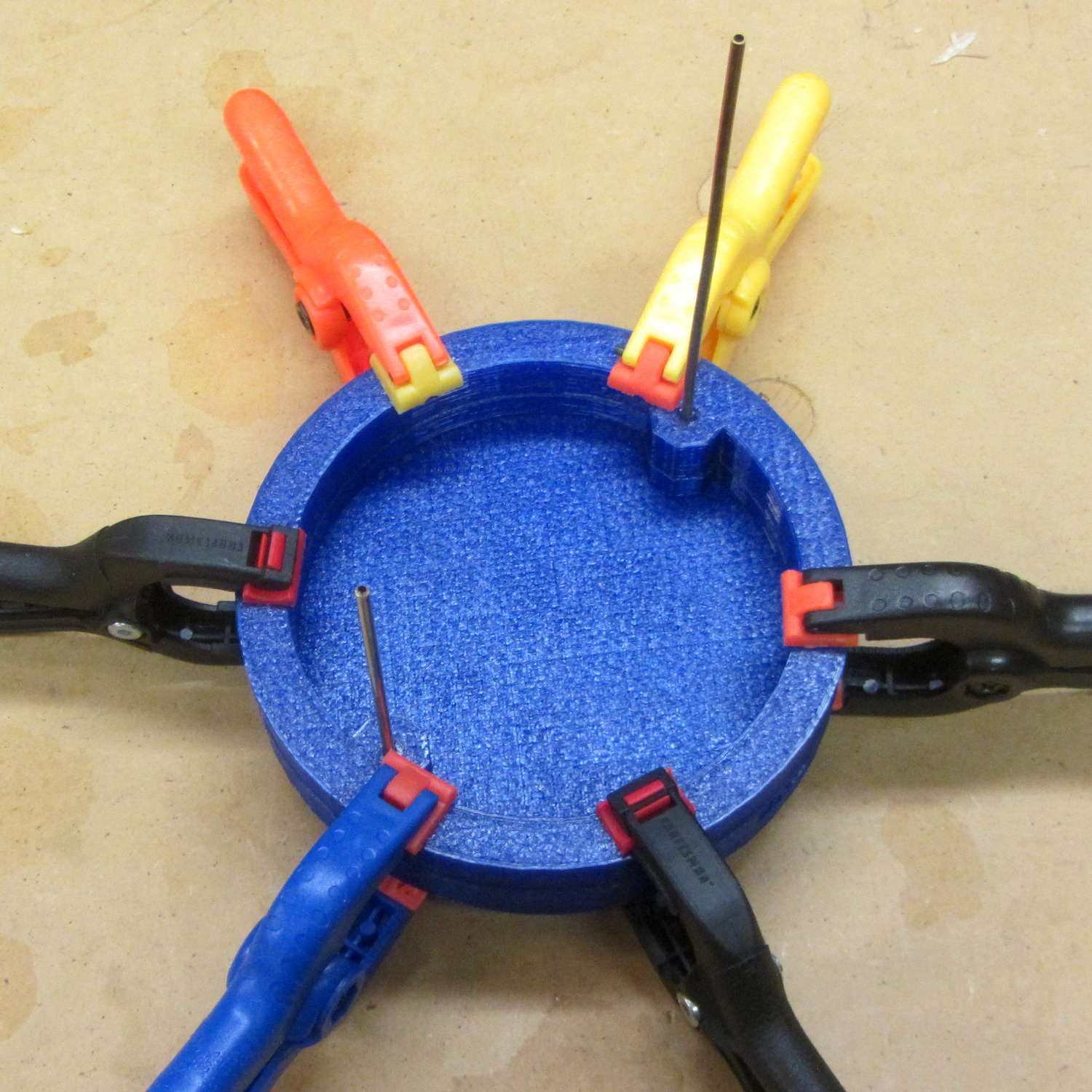
I drilled eight holes in the bottom surface of the new ring, slobbered epoxy around the ring and tucked it into the holes, used a pair of brass rods to align the two parts, and clamped them together while the epoxy cured:
Lamp Base – clamping
I should be using black PETG anyway, so we’ll call this one a prototype and move on.
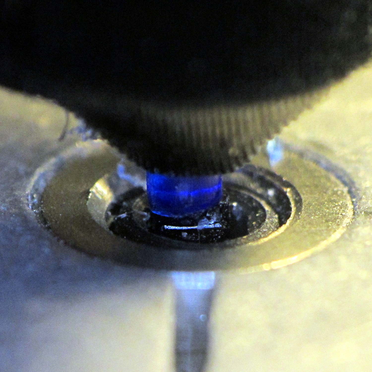
Having that knockoff Neopixel fail from overheating prompted me to measure what was going on. Because the LEDs sink most of their heat into the package leads, the back of the LED strip should be the hottest part of the package and the Mood Light’s central pillar should be pretty nearly isothermal. Despite that, I figured I should measure the temperature closer to the back of the strip, sooo I drilled a hole for the thermocouple…
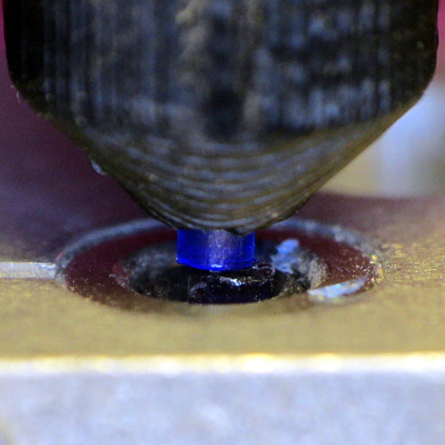
Clamp the whole Mood Light to the Sherline’s tooling plate with the pillar sides mostly square to the axes and line up the spindle 2 mm behind the LED strip:
Mood Light – aligning thermocouple hole
The two clamp pads are CD chunks, under just enough pressure to anchor the Mood Light.
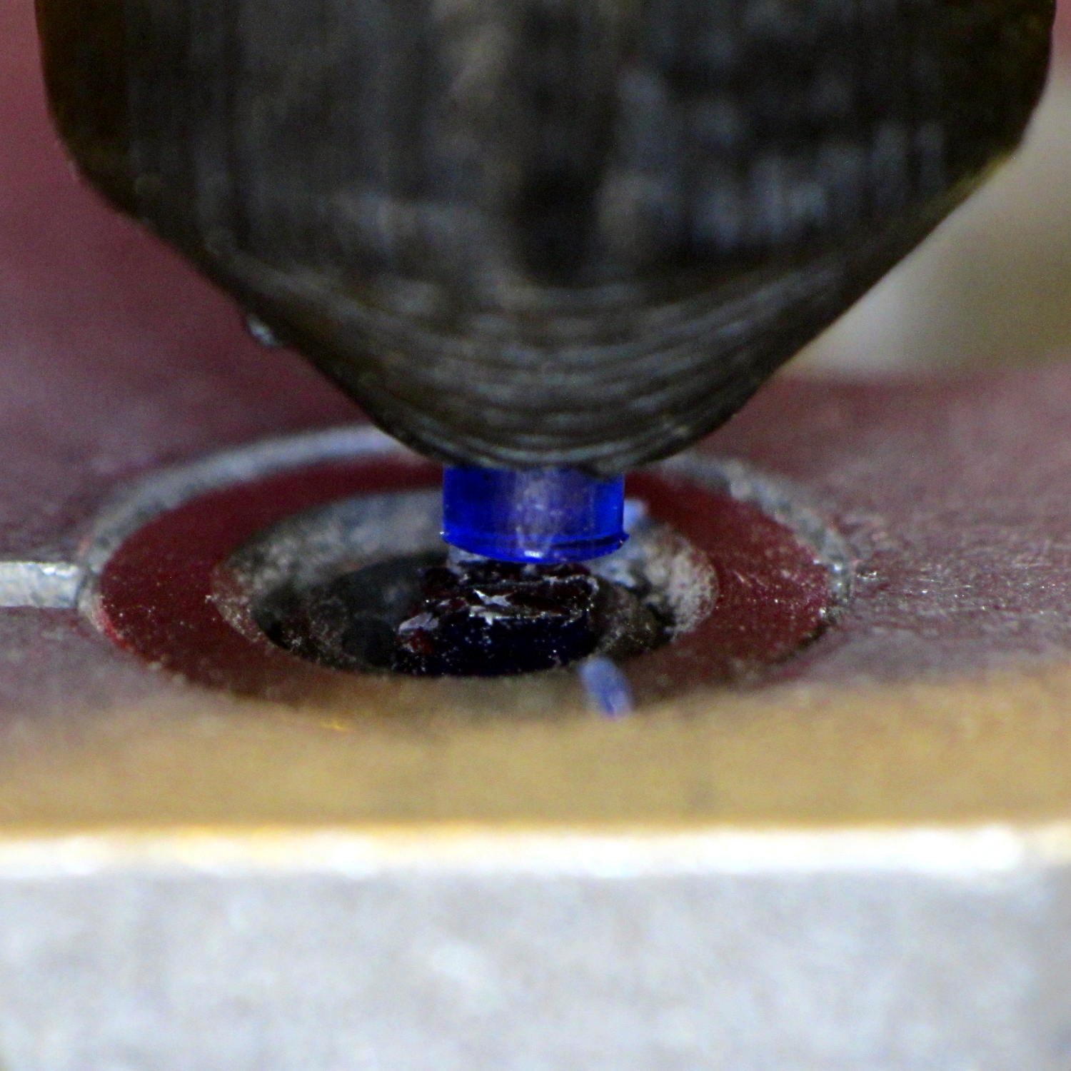
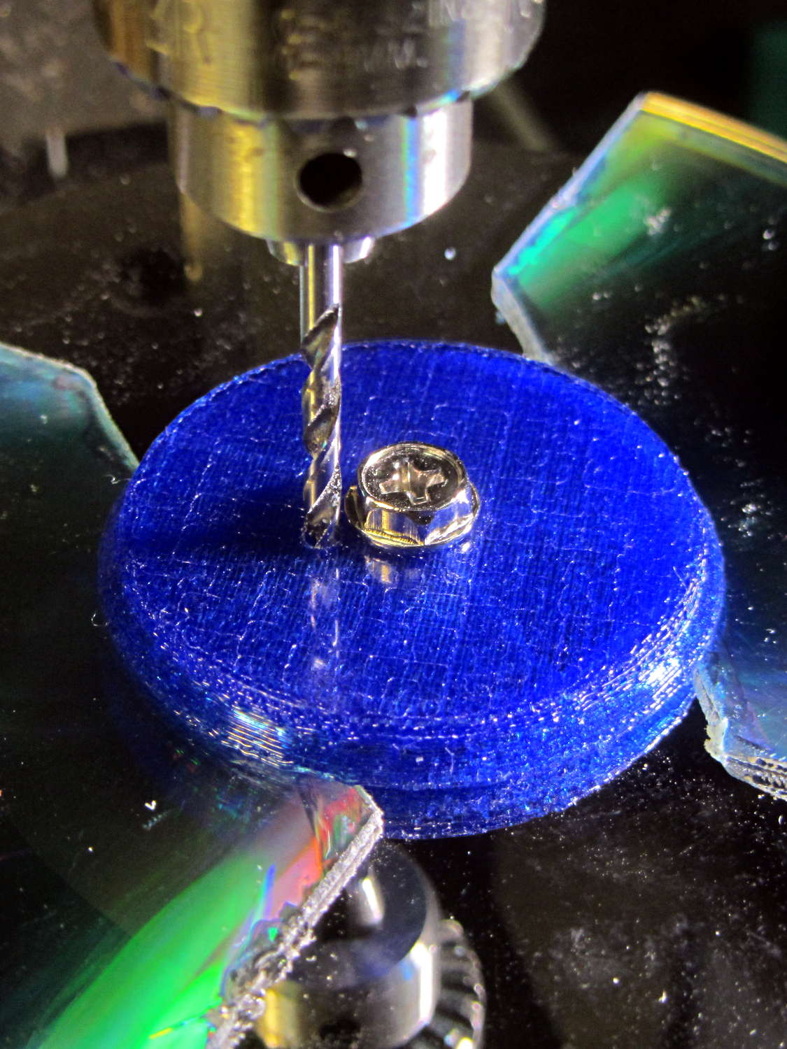
Screw the cap in place (to match-drill both holes at once) and drill a 2 mm (#46, close enough) hole down past the top LED:
Mood Light – drilling thermocouple hole
I tucked the Mood Light into a box to ward off breezes, jammed one thermocouple into the new hole, let another float over the top platter, then forced the Neopixels to display constant grayscale PWM values (R=G=B) while recording the LED and air temperatures every five minutes:
Hard Drive Mood Light – temp vs power data
That was easier and faster than screwing around with automated data collection. The data has some glaring gaps where I went off to do other things during the day.
I turned those numbers into a graph, printed it out, puzzled over it for a bit, then annotated it with useful numbers:
Hard Drive Mood Light – temp vs power data – graph
That first little blip over on the left comes from a minute or two at PWM 32; the cooling time constant works out to be a bit under 10 minutes. The warming time constant looks to be somewhat longer, but not by much.
Eyeballing the endpoint temperatures for each PWM value, feeding in the current measurements, and creating a small table:
VCC
5
V
Current
0.057
A
Package
0.285
W
Total
3.42
W
PWM
Duty
Nom Power
Failed LEDs
Net Power
°C Rise
0
0.00
0.00
0
0.00
0
32
0.13
0.43
0
0.43
6
64
0.25
0.86
0
0.86
12
85
0.33
1.14
1
1.04
16
128
0.50
1.71
1
1.62
24
192
0.75
2.57
1
2.47
35
255
1.00
3.41
4
3.03
42
The same blue LED that failed earlier dropped out again, plus another package (on a different strip) went completely dark shortly after I clobbered the LEDs with full power at PWM 255. The Net Power column deducts the power not used by the failed LEDs, under the reasonable assumption that the total heating depends on the number of active LEDs.
All the failed LEDs worked fine when they cooled to room temperature, so, whatever the failure mode might be, it’s not permanent. The skimpy WS2812B datasheet says bupkis about a protective thermal shutdown circuit, although it specs an 80 °C maximum operating junction temperature. I’ll stipulate a 20 °C temperature difference from junction to thermocouple at PWM 255, but that doesn’t explain the first blue LED failure at PWM 85.
Methinks these knockoffs will be much happier operating in the mid-30s.
Turning the last two columns of that table into a graph (minus the PWM 0 line to let the intercept float around) looks like I’m faking it:
Hard Drive Mood Light – Temperature vs Power
The Y intercept is off by less than 1 °C, which seems pretty good under the circumstances. The kink at PWM 85 shows that I probably didn’t allow enough time for the temperature to stabilize after the blue LED failed.
So, in round numbers, the thermal coefficient for a dozen knockoff Neopixels on a plastic pillar inside a stack of hard drive platters works out to 14 °C/W.
The raised sine waves in the Mood Light produce a long-term average PWM half of their maximum PWM. They’ve been perfectly happy with MaxPWM = 64 pushing them barely 6 °C over ambient, so they should continue to work fine at PWM 128 for a 12 °C rise… except, perhaps, during the hottest of mid-summer days.
Obviously, I should jam a thermistor inside the column and have the Arduino wrap a feedback loop around the column temperature…
Well, a picture of plastic on my M2’s platform, anyhow:
Digital Machinist Cover – Winter 2015
I swiped that image from Digital Machinist‘s writeup of the Winter 2015 issue. They run 3D printing articles that are vastly more technical and detail-oriented than the usual glowing PR fluff pieces found elsewhere; I’ve been writing about G-Code and 3D printing for quite a few years now.
They could have used an action shot taken earlier in that sequence, but it doesn’t fit the cover’s vertical layout:
This lamp needs a base for its (minimal) electronics:
Vacuum Tube LEDs – plate lead – overview
The solid model won’t win many stylin’ points:
Vacuum Tube Lights – lamp base solid model
It’s big and bulky, with a thick wall and base, because that ceramic lamp socket wants to screw down onto something solid. The screw holes got tapped 6-32, the standard electrical box screw size.
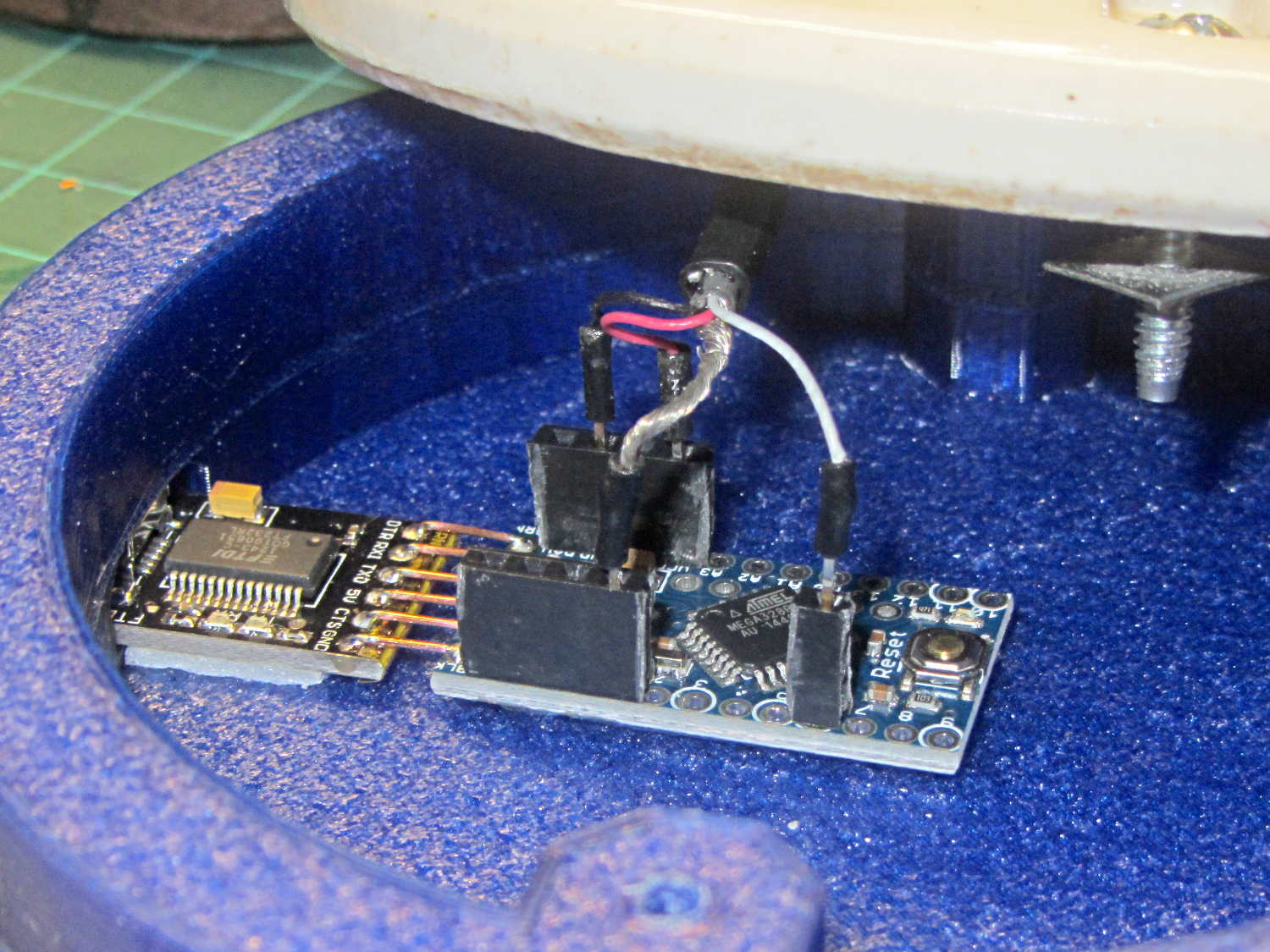
The odd little hole on the far side accommodates a USB-to-serial adapter that both powers the lamp and lets you reprogram the Arduino Pro Mini without tearing the thing apart:
Vacuum Tube Lights – USB adapter cutout
The sloped roof makes the hole printable in the obvious orientation:
Lamp Base – USB port
There’s an ugly story behind the horizontal line just above the USB adapter that I’ll explain in a bit.
The adapter hole begins 1.2 mm above the interior floor to let the adapter sit on a strip of double-sticky foam tape. I removed the standard header socket and wired the adapter directly to the Arduino Pro Mini with 24 AWG U-wires:
Lamp Base – interior
I didn’t want to use pin connectors on the lamp cable leads, but without those you (well, I) can’t take the base off without un-/re-soldering the wires in an awkward location; the fact that I hope to never take it apart is irrelevant. Next time, I’ll use a longer wire from the plate cap and better connectors, but this was a trial fit that became Good Enough for the purpose.
And then It Just Worked… although black, rather than cyan, plastic would look spiffier.
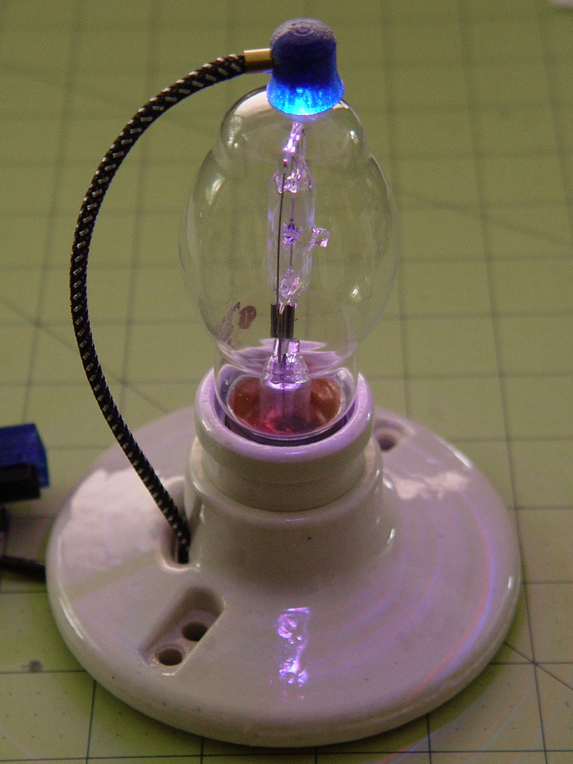
Bluish phases look icy cold:
Vacuum Tube LEDs – halogen lamp – purple phase
Reddish phases look Just Right for a hot lamp:
Vacuum Tube LEDs – halogen lamp – red phase
A ring of white double sided foam tape now holds the plate cap in place; that should be black, too.
The OpenSCAD source code adds the base to the plate cap as a GitHub gist:
This file contains hidden or bidirectional Unicode text that may be interpreted or compiled differently than what appears below. To review, open the file in an editor that reveals hidden Unicode characters.
Learn more about bidirectional Unicode characters