Ed Nisley's Blog: Shop notes, electronics, firmware, machinery, 3D printing, laser cuttery, and curiosities. Contents: 100% human thinking, 0% AI slop.
The pedal on Mary’s most recent Kenmore 158 lost its low-speed control, which meant I must add a few more graphite / carbon disks to the stacks:
Kenmore 158 – carbon disks
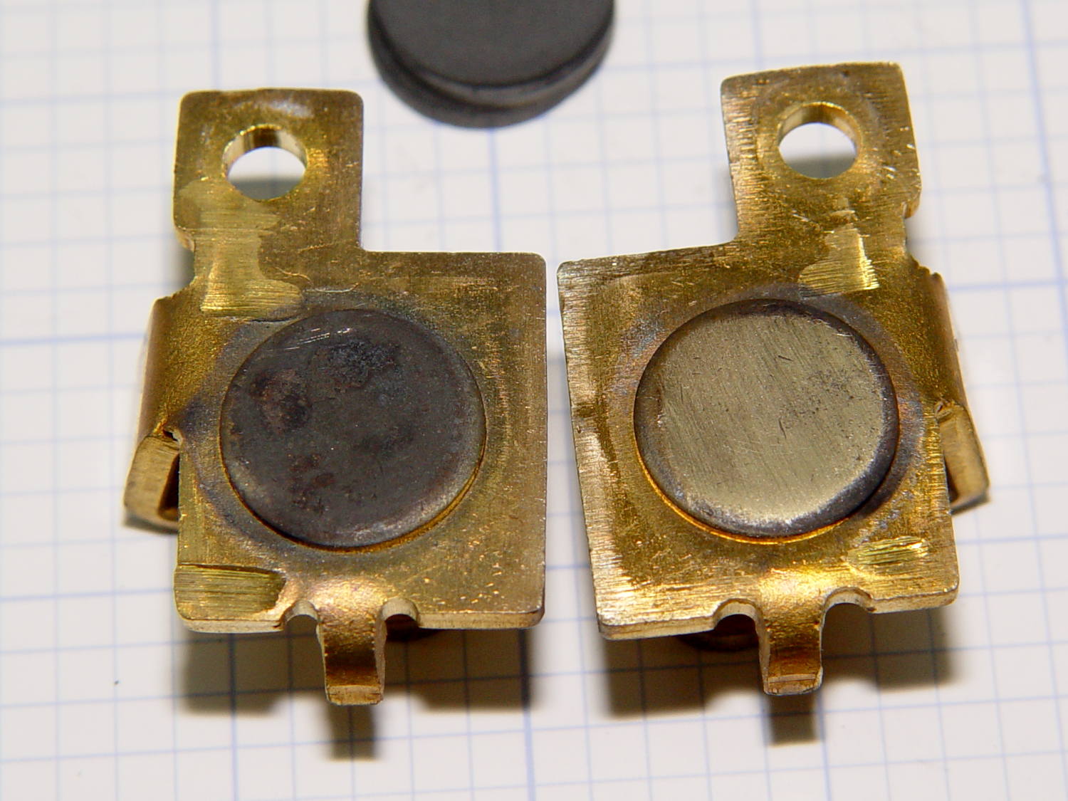
The contacts needed a bit of attention, too:
Kenmore 158 – carbon contact plates – detail
Contrary to what I found in the previousrheostats, these stacks end with a double-thick graphite disk backed up by a disk of brass shimstock, all of which needed cleaning, too. No broken disks, none severely eroded, no debris, just a general shortening of the stacks; I think the disks gradually turn into carbon dioxide.
Each stack has 42 graphite disks that average 0.79 mm thick, the double-thick disks measure 1.5 mm, and the brass shims are 0.30 mm = 12 mil. The punched contacts on those brass plates stand 0.95 mm proud of the surface.
With the big graphite plugs in place, the ceramic housing had 37 mm deep holes for the disk stacks. Subtracting the 0.95 mm contact leaves about 36 mm and, seeing as how the stacks add up to just under 36 mm overall, there’s barely room for one additional disk. I added one to each stack, buttoned the pedal up, and it works perfectly again.
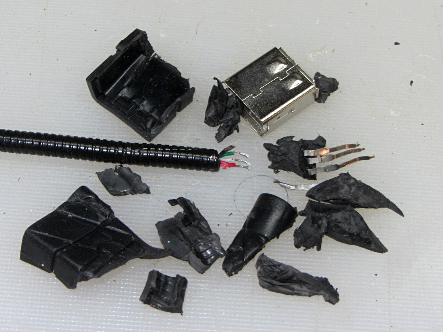
The bandsaw needs more light on the blade, but a fixed lamp will certainly get in the way of something. Pondering the solution space of available parts suggests a COB LED on a flexible gooseneck, which led to some 30 cm USB extenders, then smashing one of the connectors to reveal the wiring inside:
USB Gooseneck Extender – disassembled
It was (probably) assembled by soldering the USB terminals to the wires, mounting it in a fixture, then injection-molding the shell around everything. The injected plastic fills the end of the gooseneck and immobilizes the wires.
I’d like slightly longer wire ends, although they’re workable if I don’t make any further mistakes. Perhaps I can heatsink the gooseneck, slit 10 mm of the metal sheath with an abrasive wheel, and peel off the pieces without damaging the wires. It could happen!
Speaking of mistakes, wiring an ordinary USB connector with +12 VDC for an LED seems fraught with peril…
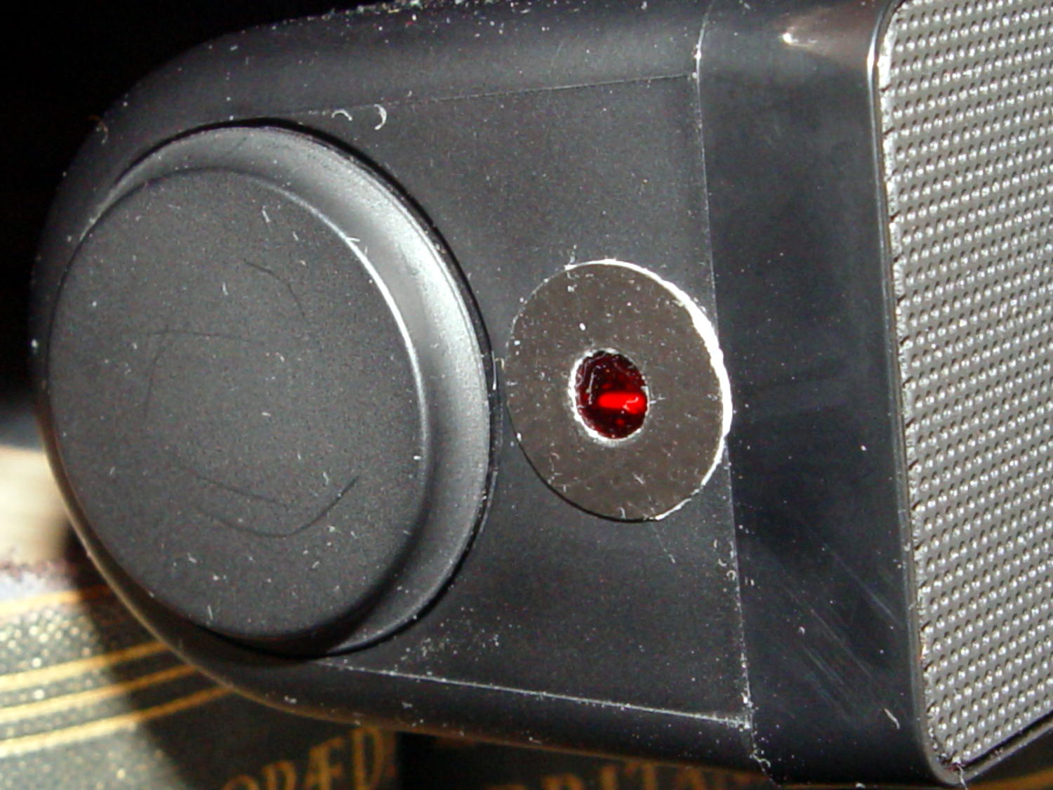
Despite its diminutive size, the white LED on the end of the Dell AC511 USB SoundBar lights up a dark bedroom surprisingly well:
Dell AC511 USB SoundBar – white power LED
That’s pretty much the only power-on indicator for the streaming players, so I didn’t want to just slap a strip of black tape over it. Instead, because white LEDs don’t emit much energy toward the red end of the spectrum, I made a cute little filter from a snippet of Primary Red gel filter material, surrounded by a black Gorilla Tape donut:
Red filter for Dell AC511 USB power LED
Two layers of Primary Red cut the light intensity to a dim glow that’s barely visible in daylight and completely inoffensive at night:
Red filter for Dell AC511 – installed
The blue activity LED on the SunFounder got the black electrical tape treatment, however, with just a sliver showing through to give a hint that it’s still active:
SunFounder RT5370 USB WiFi Adapter – masked LED
One of the other WiFi adapters has a pinhole over a red LED that’s barely visible. Another, seemingly identical one, lacks the red LED under the pinhole; when I asked the vendor about that, I was told it was removed “to save power.” Yeah, right. That was part of the motivation to try a different adapter next time around, with good results.
Of course, you must wrap an opaque black case around the Raspberry Pi to tamp down the red and green LEDs on the PCB. It’s possible to control them in software, with varying degrees of difficulty depending on which Pi you have, but …
The (relatively) new Raspberry Pi 3 PCB layout puts the Run header in a different location than in the Pi 2, but a minute of filing gnaws a suitable opening:
Raspberry Pi 3 – Reset Switch
As before, a hot-melt glue blob holds the switch in place. I’d prefer a black case, if only to hide the blob, but clear-ish is what’s available right now.
Remember those orderly shutdowns, even at the cost of a keypad button!
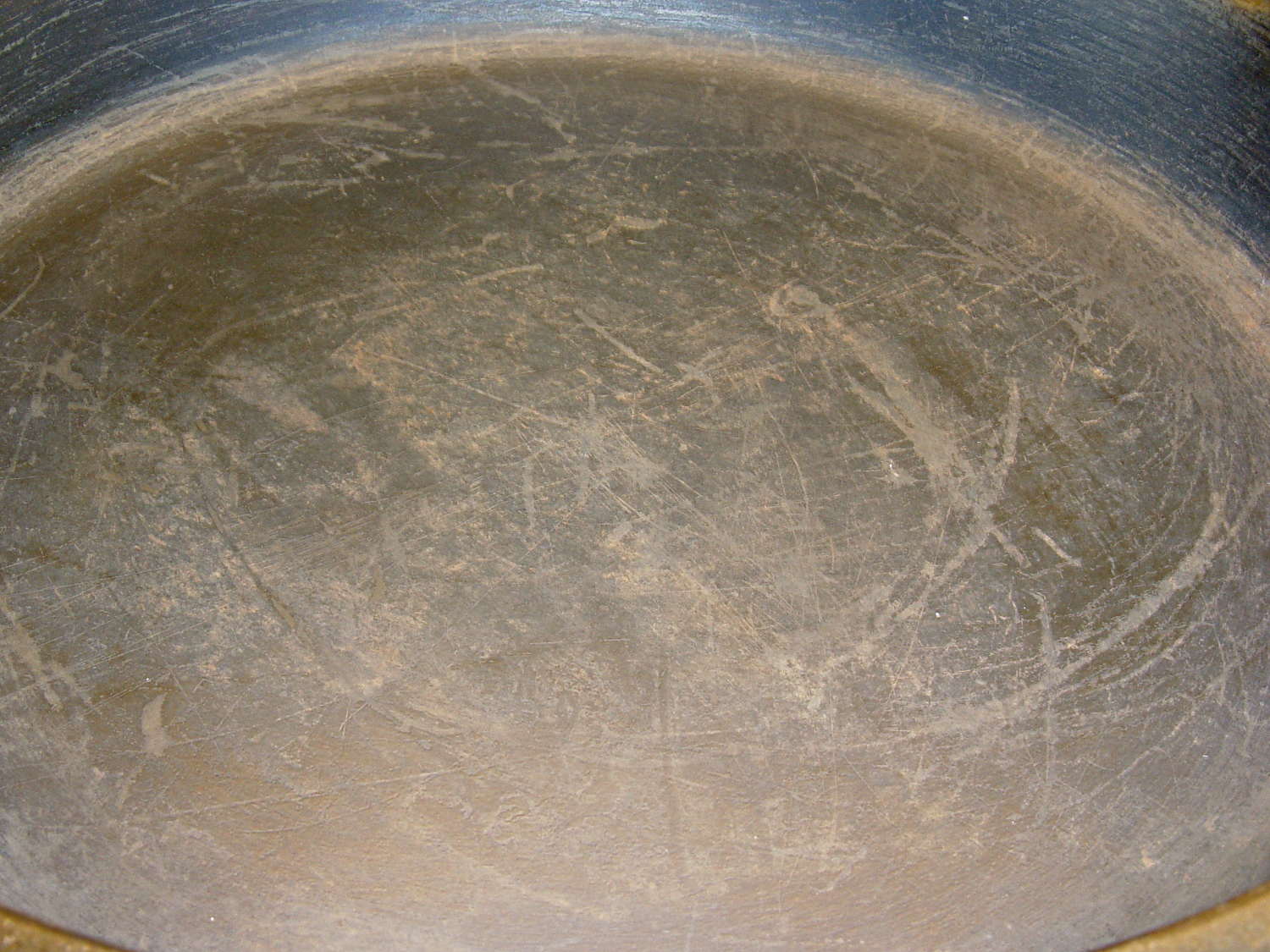
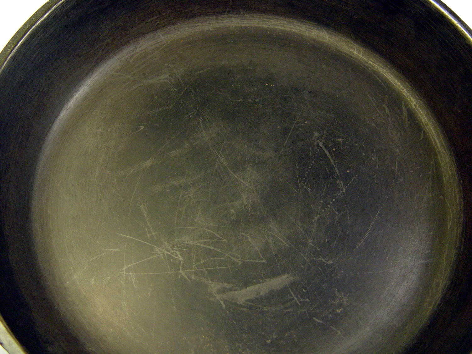
After seasoning the pan after every meal for a few weeks, then not doing that for a few more weeks, its thick glaze began looking somewhat scuffed:
Cast Iron Pan – scuffed
You may recognize some of those scars from the previous picture:
Wagner skillet – two weeks of use
Perhaps the multi-layer seasoning was entirely too thick and prone to chipping; this time, I’ll try a thinner coating. Because it’s cast iron, the pan under the coating remains undamaged.
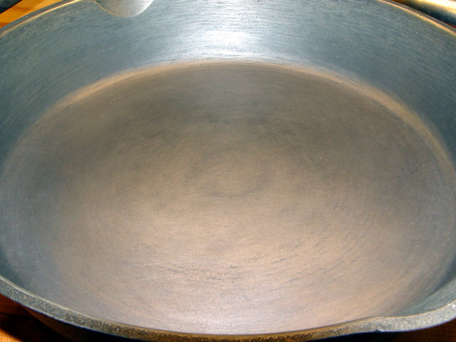
A few hours in a bucket of sodium carbonate solution with a battery charger driving a few amps through it removed most of the glaze and a few minutes with a sponge sanding block cleaned off the rest. Applying flaxseed oil and heating it to 400 °F on a regular burner (under close supervision!) produced a nice coating:
Cast Iron Pan – seasoned
The single layer was way slick for veggies in the evening and handled the morning omelet with aplomb, so we’ll run with it until something interesting happens.
As before, I put the larger spool on the floor under the lathe and let the thread spill straight off the top toward the smaller spool. This time, I didn’t have a twist accumulating in the loose thread between the two spools:
Grab longer lengths of the loose thread
Absolutely no slippage between the fingers!
Put more tension on the thread at the takeup spool
As nearly as I can tell, the thread still has a slight twist coming off the larger spool, but grabbing longer lengths captures the twist and more tension lays it on the smaller spool. After cutting the thread, what was left had maybe three turns of twist, which was no big deal and obviously hadn’t accumulated.
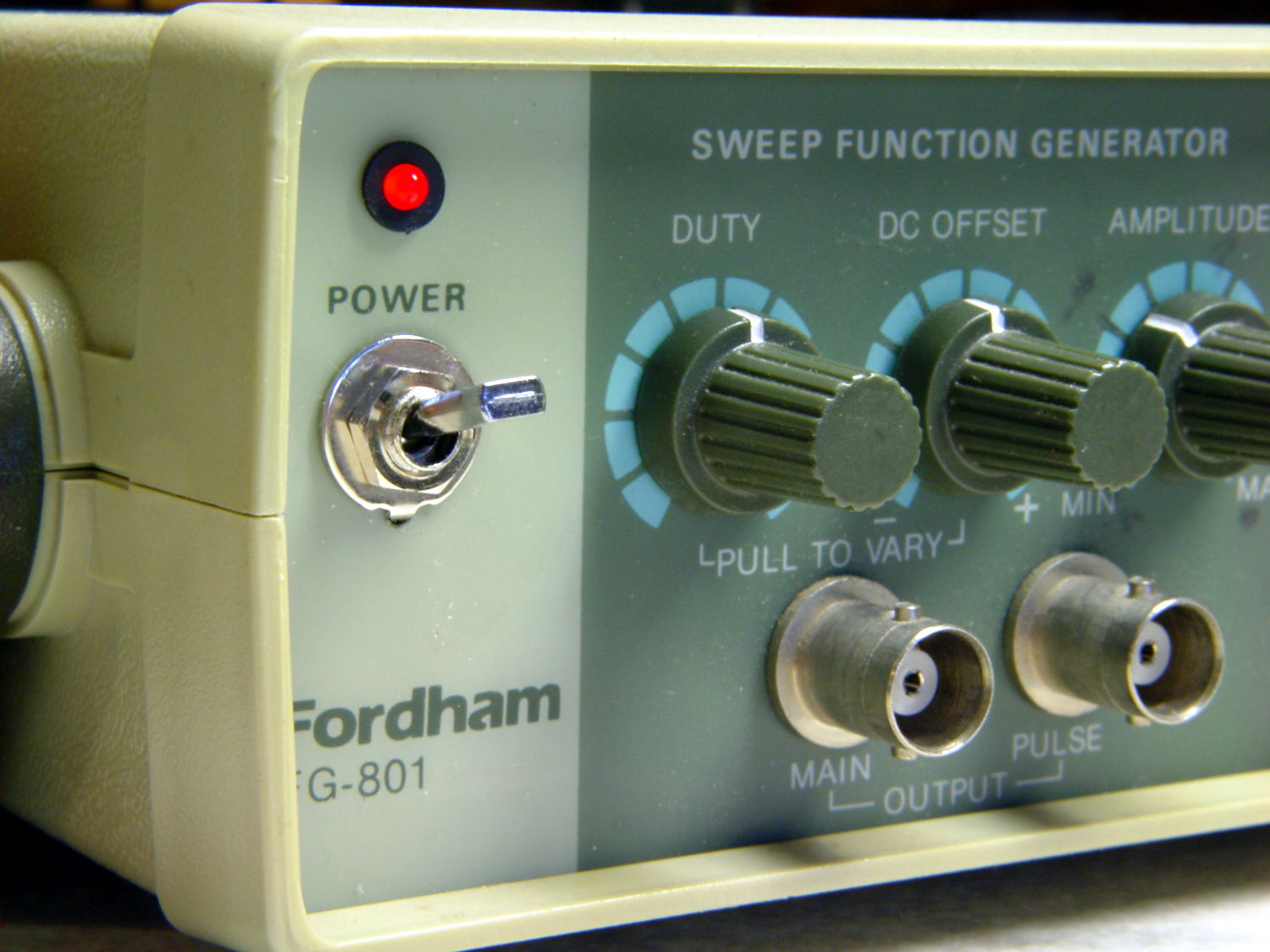
The power switch in my trusty Fordham FG-801 Function Generator failed with an accumulation of oxidation / crud on the contacts. That’s fix-able, but the switch contained not one, but two powerful springs, and puked its guts all over the floor around the Squidwrench Operating Table. Even with (a preponderance of) the parts in hand, I couldn’t figure out how to reassemble the thing; the only way out was to replace the switch.
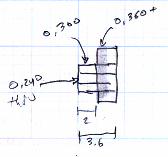
The OEM switch had a 0.360+ inch diameter pushbutton that fit into a ⅜ inch hole and, alas, my remaining stock of line-voltage switches had toggle levers and used ¼ inch holes. So I converted a bit of aluminum rod into a suitable bushing:
Fordham FG-801 Fn Gen – new switch hardware
The lock washer in the middle started with a much wider tab that I filed down into a tooth for the dent from a #2 center drill. Protip: center drills don’t walk off like twist drills, even when you hand-hold the front panel at the drill press with all the electronics dangling below.
The bushing dimension doodle:
Fordham FG-801 Function Generator – Replacement Switch Bushing
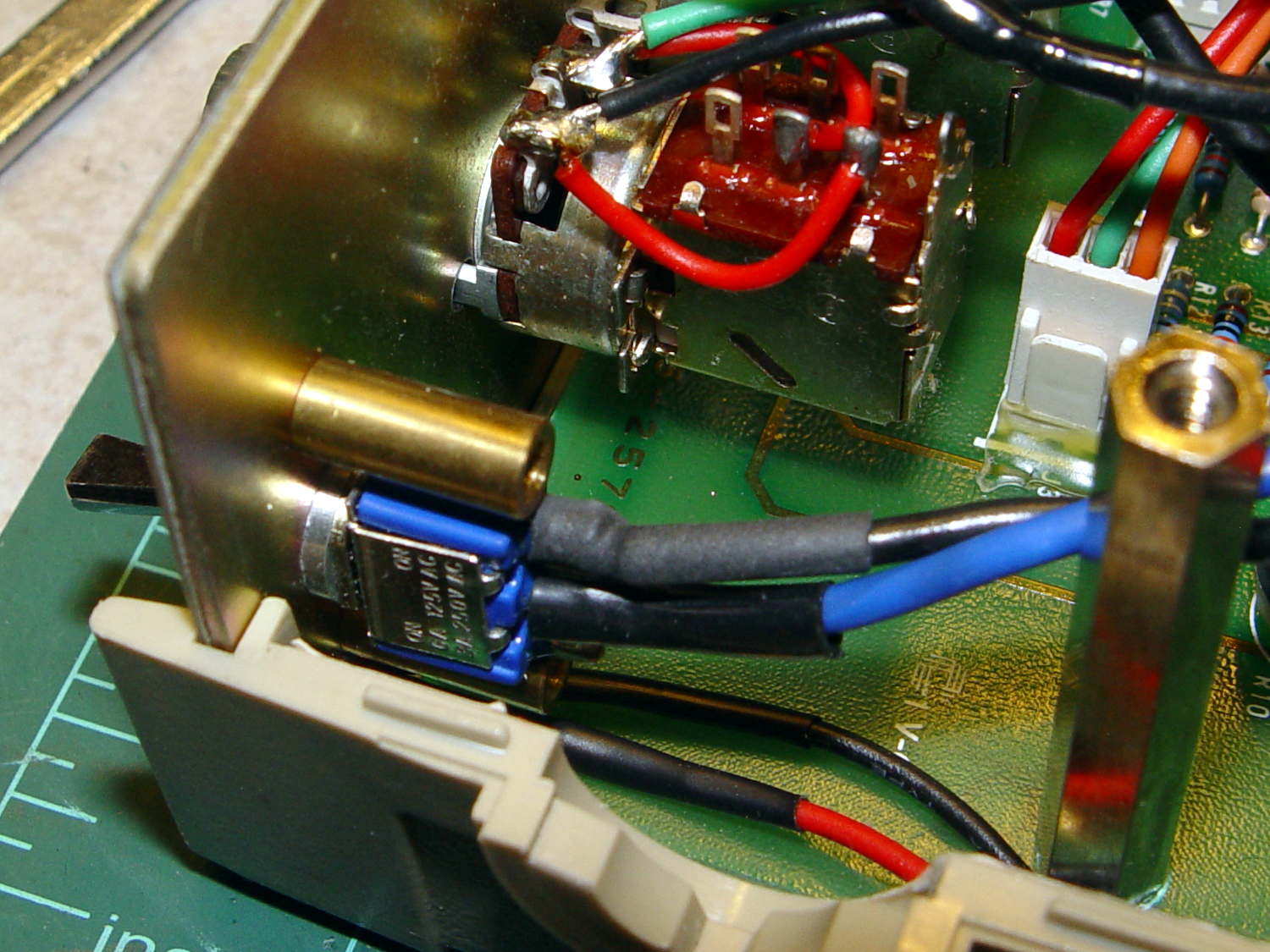
The internal wiring routes the 120 VAC line conductor to the switch, then to the fuse, then to the transformer. I don’t know whether it’s better to have an unfused switch or an unswitched fuse (surely there’s a UL spec for that), but I didn’t change anything. The new switch, being slightly smaller and mounting directly on the panel, required a new wire (the blue one) from the fuse:
Fordham FG-801 Fn Gen – power switch – installed
The OEM switch mounted on two round brass standoffs and, wonder to tell, the new switch fit between them!
From the front, the new switch looks like it grew there:
Fordham FG-801 Fn Gen – switch in action
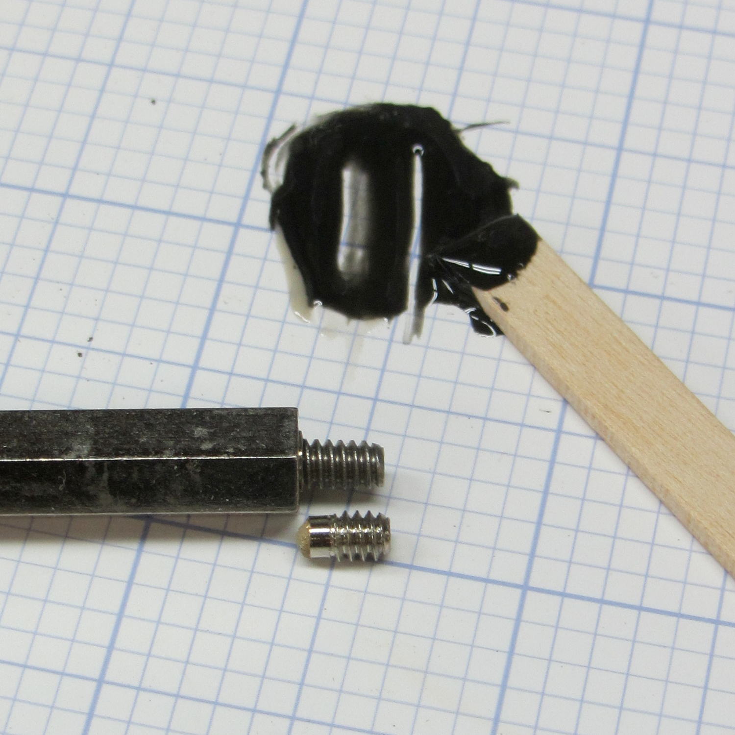
The PCB mounts to the top of the case with one screw and four hexagonal brass standoffs. The standoffs have 6-32 tapped holes on one end and a 6-32 stud on the other; one of those stud had broken off. A 6-32 stainless steel screw secured in a clearance hole with a dab of epoxy solved that problem:
Fordham FG-801 Fn Gen – standoff stud
I stood it vertically and tweaked the screw to be perpendicular while the epoxy cured.
Memo to Self: The next time around, put a nut on the stud to make sure the answer comes out right. I didn’t do this time to avoid epoxying the nut to the standoff.