The power switch in my trusty Fordham FG-801 Function Generator failed with an accumulation of oxidation / crud on the contacts. That’s fix-able, but the switch contained not one, but two powerful springs, and puked its guts all over the floor around the Squidwrench Operating Table. Even with (a preponderance of) the parts in hand, I couldn’t figure out how to reassemble the thing; the only way out was to replace the switch.
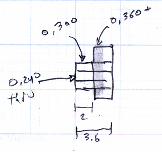
The OEM switch had a 0.360+ inch diameter pushbutton that fit into a ⅜ inch hole and, alas, my remaining stock of line-voltage switches had toggle levers and used ¼ inch holes. So I converted a bit of aluminum rod into a suitable bushing:

The lock washer in the middle started with a much wider tab that I filed down into a tooth for the dent from a #2 center drill. Protip: center drills don’t walk off like twist drills, even when you hand-hold the front panel at the drill press with all the electronics dangling below.
The bushing dimension doodle:
The internal wiring routes the 120 VAC line conductor to the switch, then to the fuse, then to the transformer. I don’t know whether it’s better to have an unfused switch or an unswitched fuse (surely there’s a UL spec for that), but I didn’t change anything. The new switch, being slightly smaller and mounting directly on the panel, required a new wire (the blue one) from the fuse:
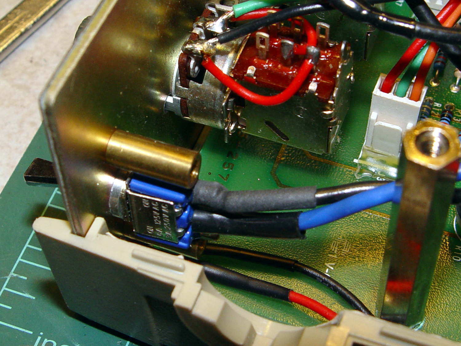
The OEM switch mounted on two round brass standoffs and, wonder to tell, the new switch fit between them!
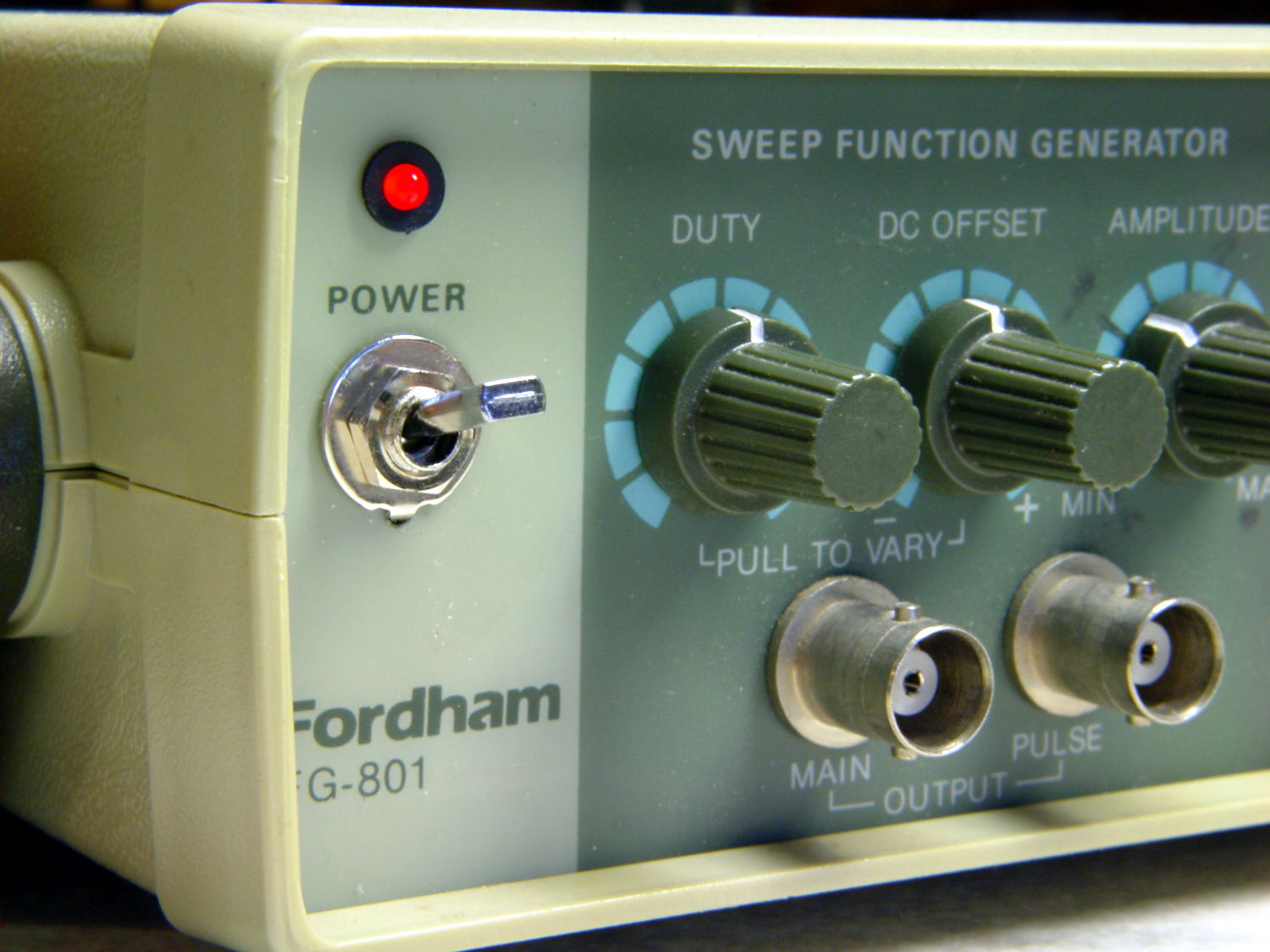
From the front, the new switch looks like it grew there:
The PCB mounts to the top of the case with one screw and four hexagonal brass standoffs. The standoffs have 6-32 tapped holes on one end and a 6-32 stud on the other; one of those stud had broken off. A 6-32 stainless steel screw secured in a clearance hole with a dab of epoxy solved that problem:
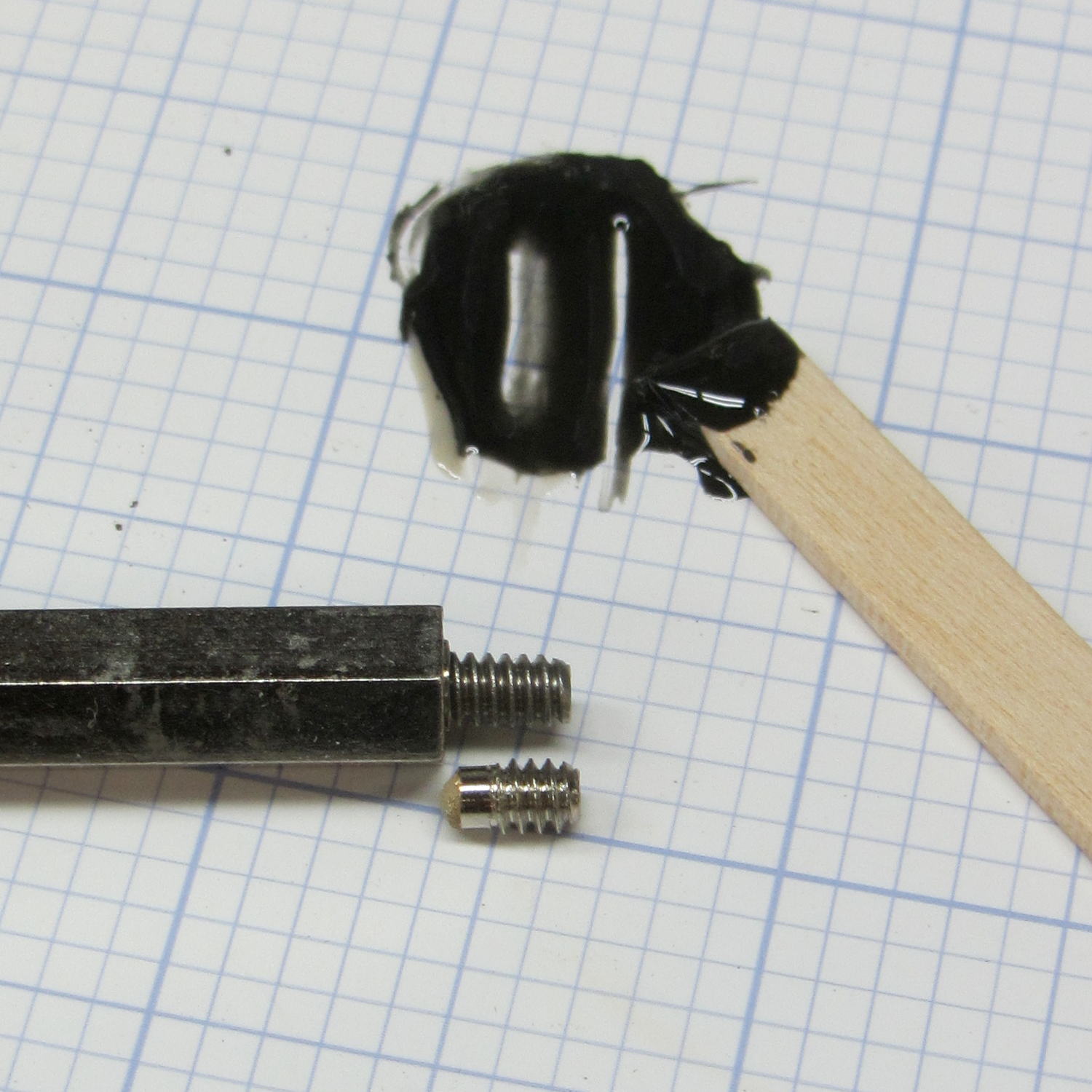
I stood it vertically and tweaked the screw to be perpendicular while the epoxy cured.
Memo to Self: The next time around, put a nut on the stud to make sure the answer comes out right. I didn’t do this time to avoid epoxying the nut to the standoff.
Done!

Comments
12 responses to “Fordham FG-801 Function Generator Power Switch”
Nice fix. Most of my line voltage switches are big chunky ones that wouldn’t look as appropriate there.
I was so happy I saved those little switches…
What epoxy is that? It’s an awfully pretty color.
Good old JB Kwik fast-cure steel-filled epoxy from fresh tubes. It’s darker gray than slow-cure JB Weld, which may have more to do with my imprecise mixing of small quantities than anything else.
I use JB’s filled epoxies everywhere their color doesn’t matter. The antenna splice got clear epoxy, because even I balk at black blobs on natural PETG…
I had hopes that the steel-filled JB Weld would be conductive, but no luck. Beyond that, JB Weld is my go-to product
I’ve used conductive silver-filled epoxy decades ago, but I’m not going there. They’re not terribly user friendly, either (IIRC, we had to keep it in the freezer; premixed with a room-temp cure. Shelf life was weeks.)
Electrically insulating and thermally conducting: how does it know? [grin]
The draw-able circuits craze brought silver-loaded ink back for a while, but I think that whole effort sank without a trace. Something to do with precious metal prices, methinks…
You can add filler of your choice to any epoxy up to around peanut butter consistency. With normal formulas you mix A and B and then mix in the filler. For 5 minute variants you might want to mix in filler with component A and then add B to allow for more working time.
I never tried to make a conductive epoxy, but I do mix an odd batch of graphite filled RTV silicone to resurface silicone membranes in remote controllers. Trick is to add enough graphite for the mix to be conductive but not so much that it looses structural integrity. I guess there’s no reason why it wouldn’t work with epoxy. Metal dust might work better than graphite though.
The model makers use glass microbeads to mix in epoxy for lightweight filler. I found the cured mix can be removed with a moderate amount of heat in case things go awry.
Epoxies tend to have relatively low Tglass temperature. Rule of thumb is Tg will be around 20C higher then the cure temperature limited by maximum Tg specific for each product. That means they will soften when heated, but also that you can post-cure them at higher-then-room temperatures. Some aviation grade resins like L285 can get to almost 100C Tg, but I suspect that 5 minute types have significantly lower maximum Tg as shorter cure times usually mean weaker final product.
Ah-ha! That explains slow-cure JB Weld’s 550 °F rating vs. fast-cure JB Kwik’s 300 °F. They don’t give a formal Tg for either, but “can withstand temperatures up to” probably means the Tg is at least a little bit higher.
I’ve read somewhere (and although that doesn’t make it true it does make a kind of sense) that parts A and B are reacting while they can get close to each other. As the matrix cures, molecules are less mobile and are more unlikely to find themselves next to their opposite numbers. The curing process stops when they are all immobile.
By heating it up in post curing, you allow additional mobility which results in additional curing.
In fast processes however, components have less open time, they get immobilized sooner and cure is less complete.
This could be completely wrong but it aligns with empirical evidence quite nicely :)
[…] While I had the case open, I checked the FG-801’s calibration: […]