The Smell of Molten Projects in the Morning

Ed Nisley's Blog: Shop notes, electronics, firmware, machinery, 3D printing, laser cuttery, and curiosities. Contents: 100% human thinking, 0% AI slop.

Category: Machine Shop

Mechanical widgetry

  • Bandsaw Worklight

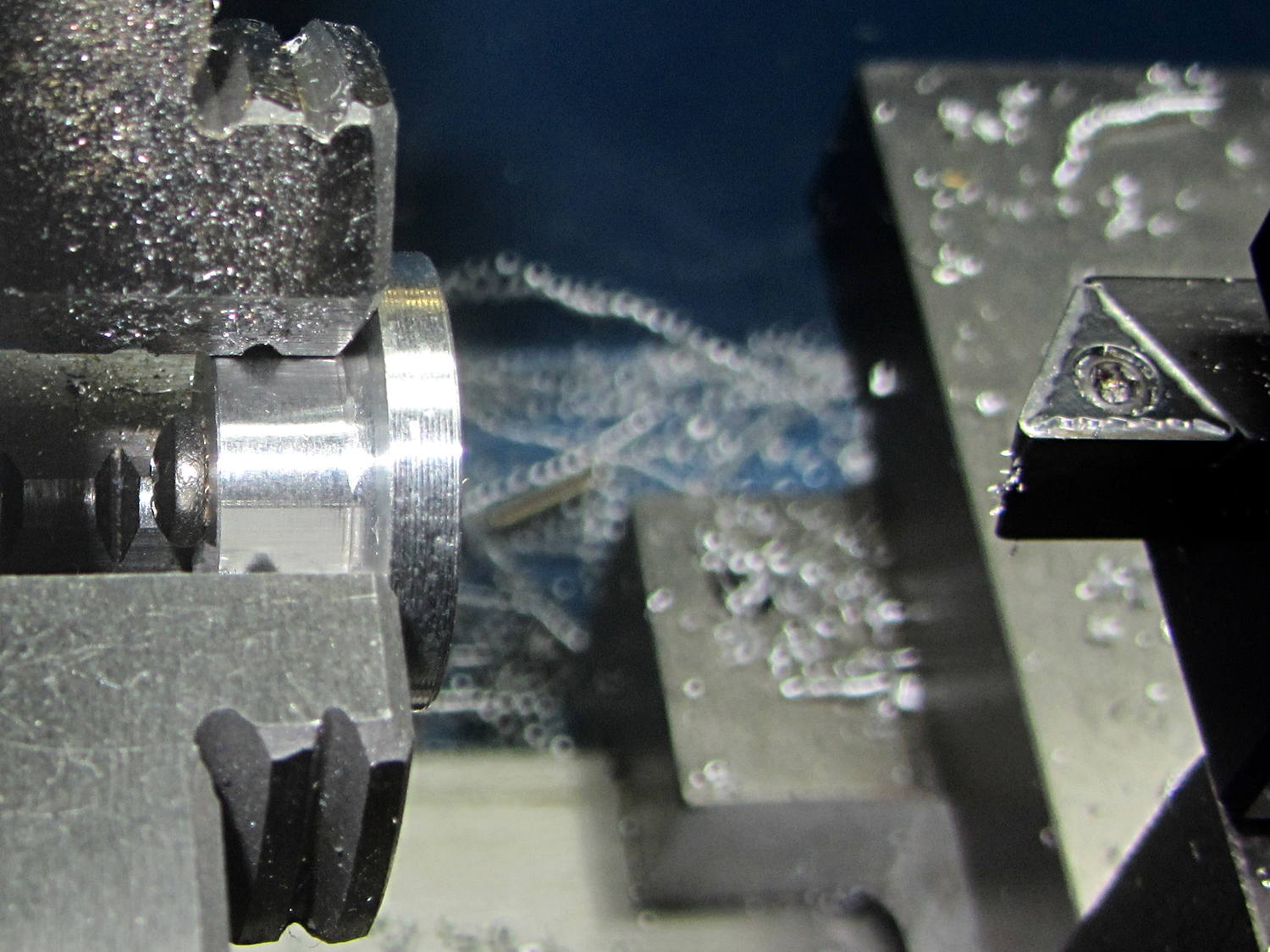
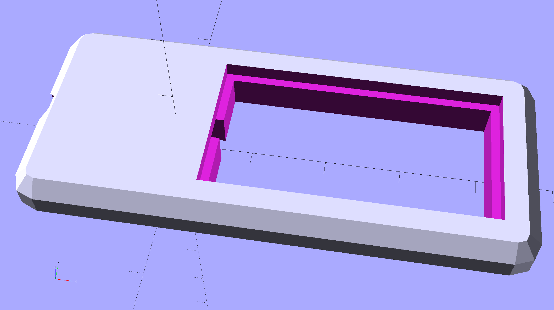
    Having hacked back the end of the USB gooseneck extension, a tweak of the COB LED heatsink mount for my desk lamp produces a smaller version for a 1.8 W LED:

    Chip On Board Heatsink Mount - Bandsaw Lamp - solid model
    Chip On Board Heatsink Mount – Bandsaw Lamp – solid model

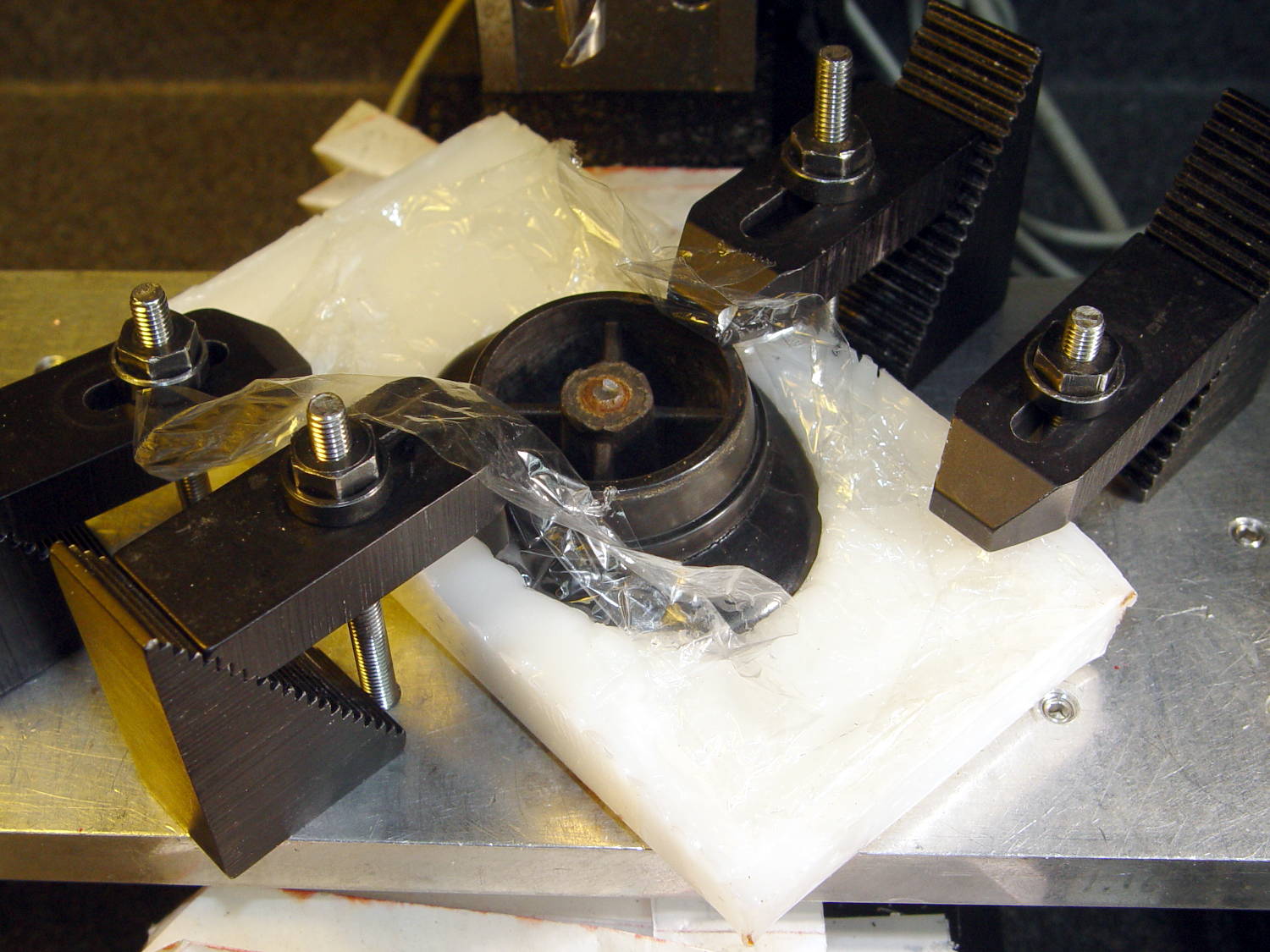
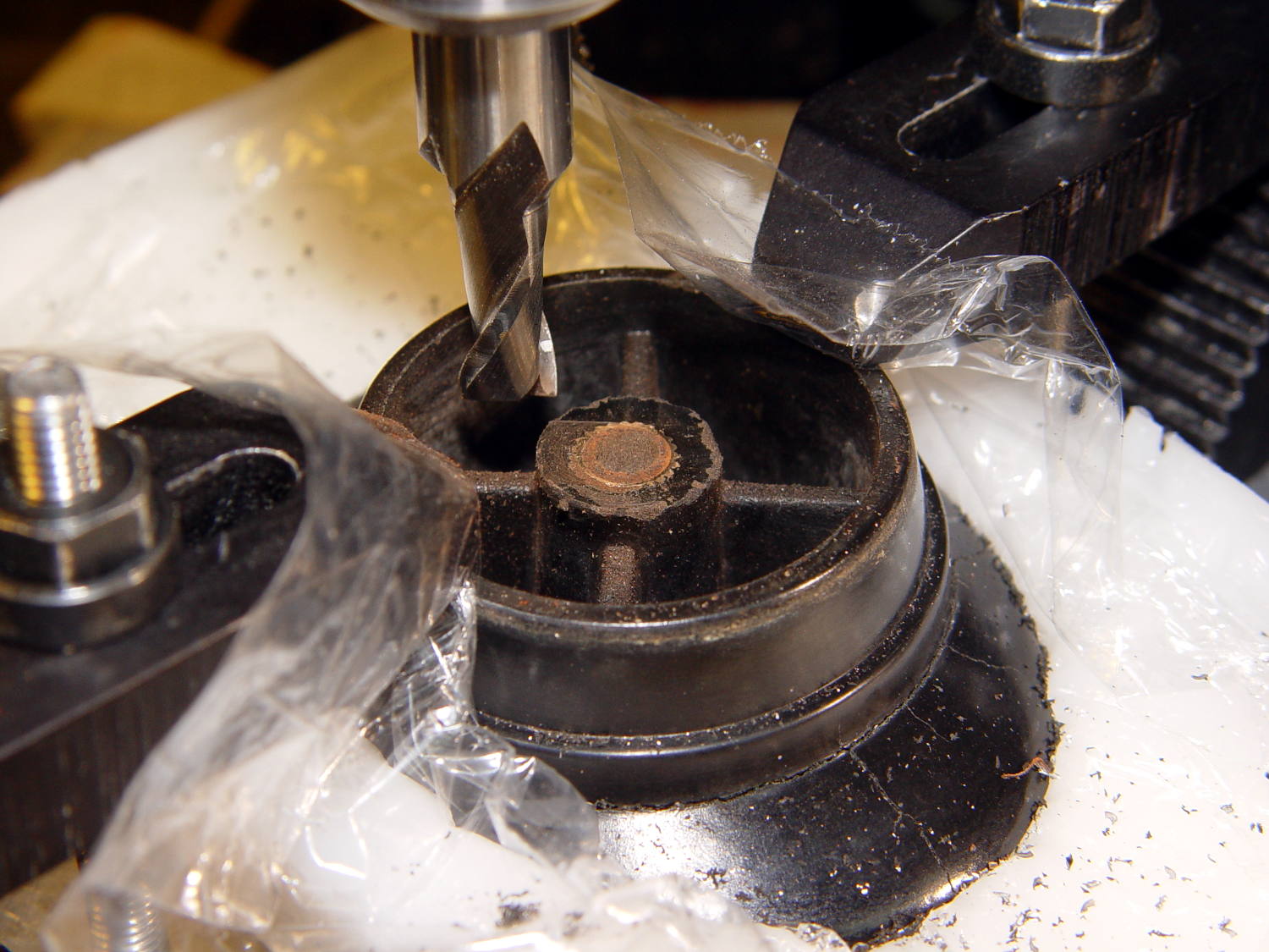
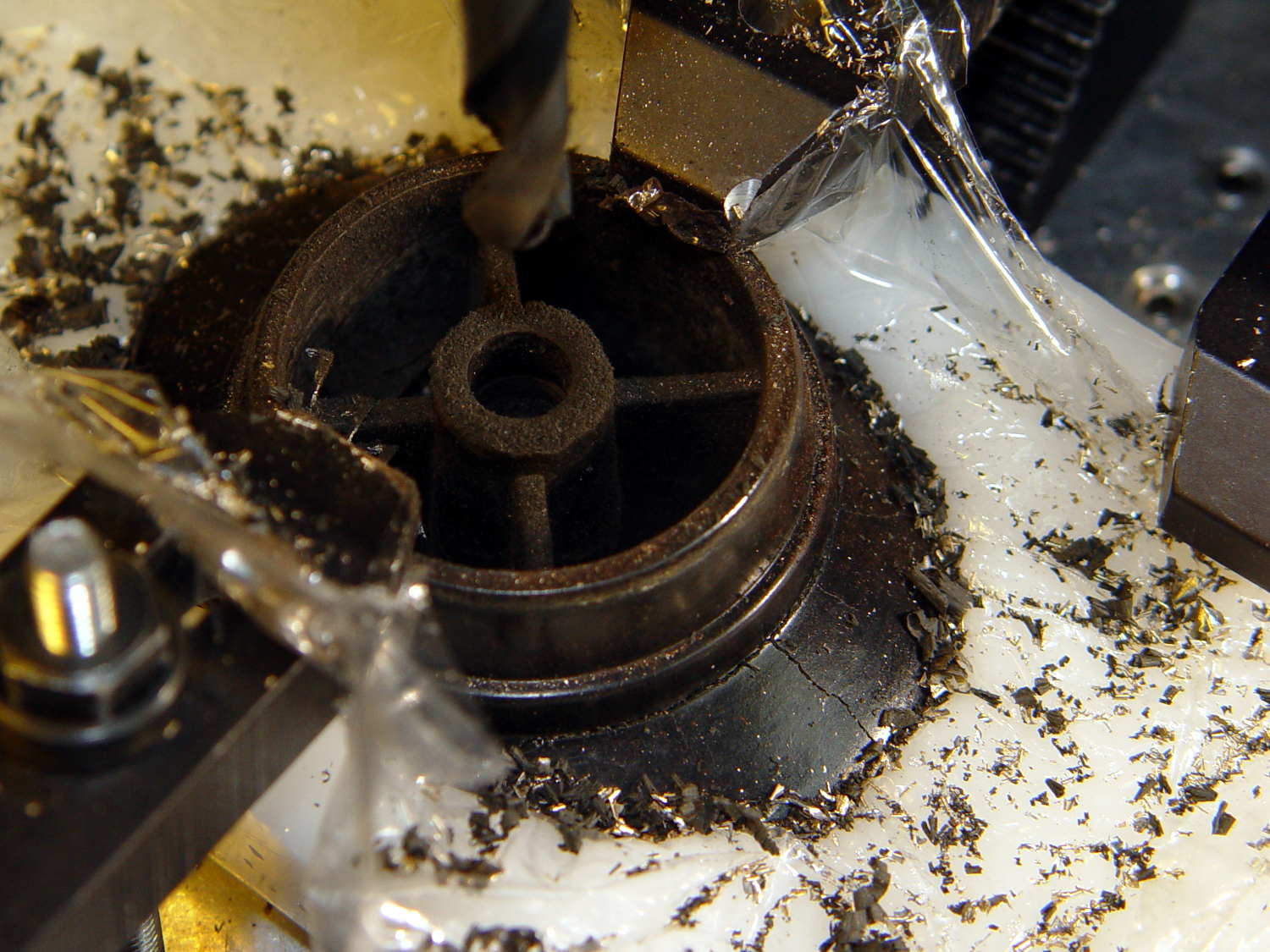
    That fits half of a random heatsink, bandsawed just to the far side of the middle fin and milled flat.

    Ream out the 5 mm hole with a #8 drill for a snug fit around the gooseneck, jam gooseneck in place, dab epoxy on the corners of the recess, mash the heatsink in place, solder wires to LED, smear epoxy on the aluminum backplate, clamp while curing:

    USB Gooseneck - LED assembly
    USB Gooseneck – LED assembly

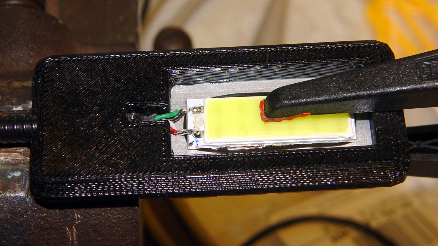
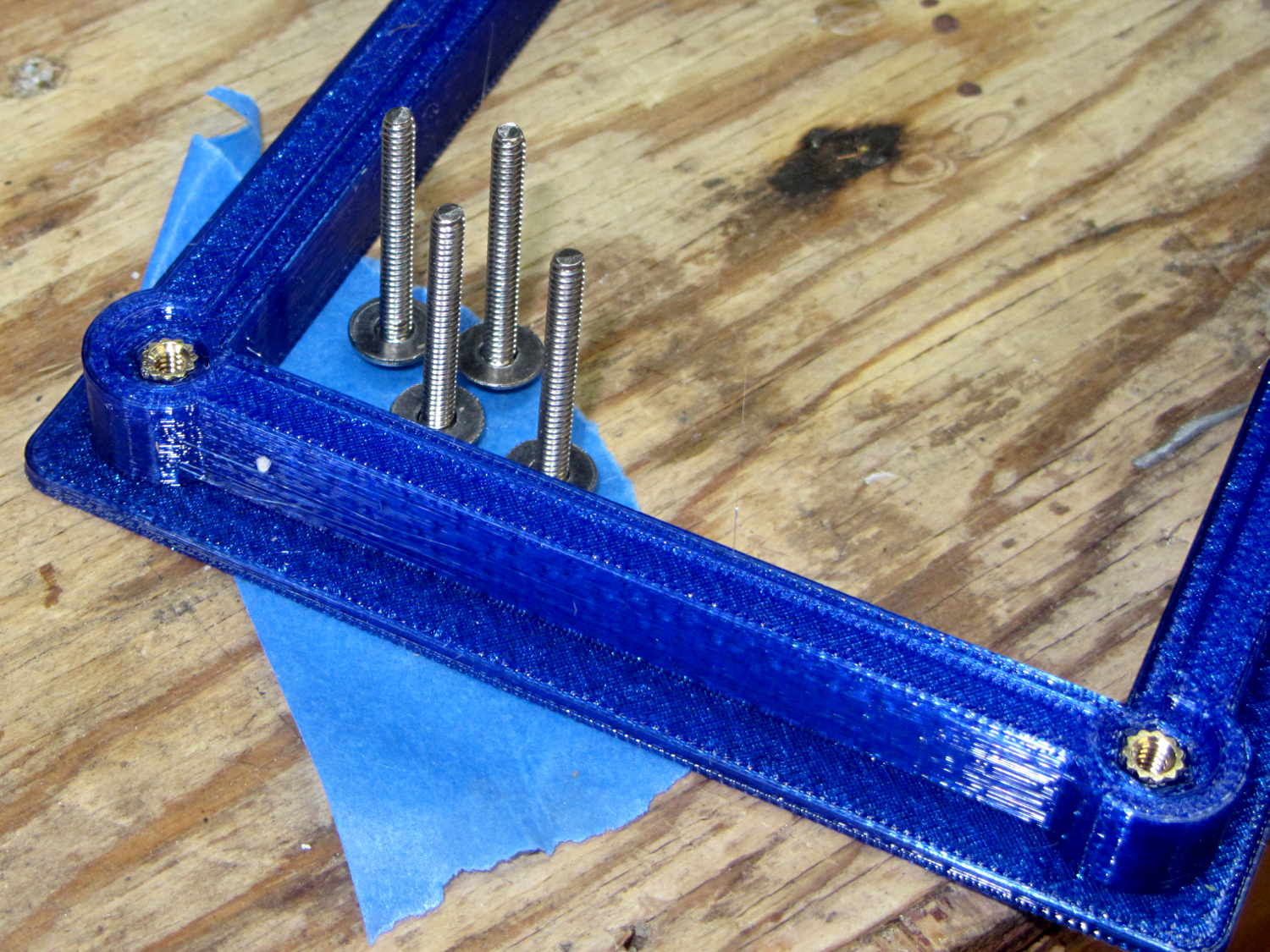
    And it looks pretty good, if I do say so myself:

    USB Gooseneck - on bandsaw
    USB Gooseneck – on bandsaw

    The hook-n-loop tape holding the cable to the bandsaw gotta go, but should suffice until I conjure a better mount.

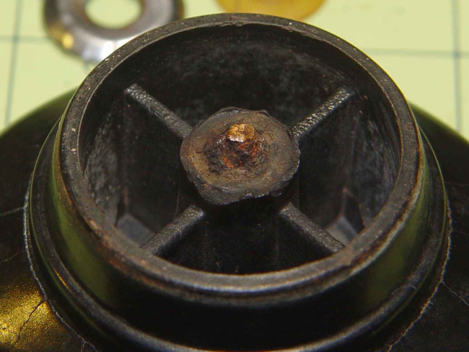
    The alert reader may wonder how a 9 V COB LED runs from a 5 V USB cable with nary a trace of a voltage booster to be seen. Well, that’s not really a USB cable any more; I paralleled the red+white and black+green wires for lower resistance, then hacked a 9 VDC power supply into an old USB hub:

    Hacked USB hub - PCB mods
    Hacked USB hub – PCB mods

    I ripped out the upstream USB plug, hotwired the 9 V supply where the 5 V USB wires used to be, soldered jumpers on the downstream sockets to short the outer two pin pairs together, razor-knifed the power leads going into the epoxy-blobbed USB controller, and declared victory:

    Hacked USB hub - in use
    Hacked USB hub – in use

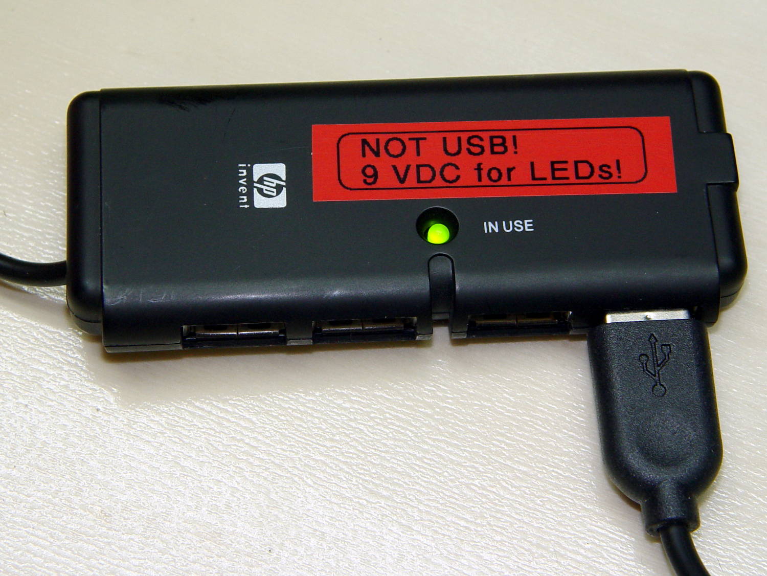
    Admittedly, that “In Use” LED runs a bit brighter now.

    I have a few other tools on that bench in need of LED lights; when I build ’em, they can all plug into this hub. No reason to invent new connectors & cables & all that. It may need a power switch.

    Turns your stomach, eh?

    The OpenSCAD source code as a GitHub Gist:

    // Chip-on-board LED light heatsink mount for desk lamp
    // Ed Nisley KE4ZNU December 2015
    // February 2017 – rectangular COB, smaller heatsink
    Layout = "Show"; // Show Build
    //- Extrusion parameters must match reality!
    ThreadThick = 0.25;
    ThreadWidth = 0.40;
    HoleWindage = 0.2;
    Protrusion = 0.1; // make holes end cleanly
    inch = 25.4;
    function IntegerMultiple(Size,Unit) = Unit * ceil(Size / Unit);
    //———————-
    // Dimensions
    ID = 0; // for round things
    OD = 1;
    LENGTH = 2;
    Gooseneck = [3.0,5.0,15.0]; // anchor for end of gooseneck
    COB = [30.0,11.0,2.5]; // Chip-on-board LED module
    Heatsink = [37.1,19.2,10.0]; // overall
    HeatsinkBase = 2.0; // solid base below fins
    HSLip = 1.0; // width of lip under heatsink
    BaseMargin = 2*2*ThreadWidth;
    BaseRadius = 3*ThreadThick + Gooseneck[OD]/2; // defines slab thickness
    BaseSides = 2*4;
    Base = [(Gooseneck[LENGTH] + Gooseneck[OD] + Heatsink[0] + 2*BaseRadius + BaseMargin),
    (Heatsink[1] + 2*BaseRadius + 2*BaseMargin),
    2*BaseRadius];
    echo(str("Slab thickness: ",Base[2]));
    //———————-
    // Useful routines
    module PolyCyl(Dia,Height,ForceSides=0) { // based on nophead's polyholes
    Sides = (ForceSides != 0) ? ForceSides : (ceil(Dia) + 2);
    FixDia = Dia / cos(180/Sides);
    cylinder(r=(FixDia + HoleWindage)/2,
    h=Height,
    $fn=Sides);
    }
    //– Lamp heatsink mount
    module Lamp() {
    difference() {
    translate([(Base[0]/2 – BaseRadius – Gooseneck[LENGTH]),0,0])
    hull()
    for (i=[-1,1], j=[-1,1])
    translate([i*(Base[0]/2 – BaseRadius),j*(Base[1]/2 – BaseRadius),Base[2]/2])
    sphere(r=BaseRadius/cos(180/BaseSides),$fn=BaseSides);
    translate([(Heatsink[0]/2 + Gooseneck[OD]), // main heatsink recess
    0,
    (Base[2] + Heatsink[2]/2 – HeatsinkBase)])
    cube((Heatsink + [HoleWindage,HoleWindage,0.0]),center=true);
    translate([(Heatsink[0]/2 + Gooseneck[OD]),0,HeatsinkBase]) // lower lip to shade lamp module
    scale([1,1,2])
    cube(Heatsink – [2*HSLip,2*HSLip,0],center=true);
    translate([0,0,Base[2]/2]) // goooseneck insertion
    rotate([0,-90,0]) rotate(180/8)
    PolyCyl(Gooseneck[OD],Base[0],8);
    translate([0,0,Base[2]/2 + Gooseneck[ID]/2]) // wire exit
    rotate([180,0,0])
    PolyCyl(Gooseneck[ID],Base[2],6);
    translate([Gooseneck[OD],0,(Base[2] – HeatsinkBase – Protrusion)/2]) // wire slot
    rotate([180,0,0])
    cube([2*Gooseneck[OD],Gooseneck[ID],(Base[2] – HeatsinkBase + Protrusion)],center=true);
    }
    }
    //———————-
    // Build it
    if (Layout == "Show") {
    Lamp();
    }
    if (Layout == "Build") {
    }


  • USB Gooseneck: Unwinding

    The USB gooseneck extension consists of a spring-steel helix with an aluminum filler strip to smooth the outside:

    USB Gooseneck - filler unwound
    USB Gooseneck – filler unwound

    A pin vise holds the intact part of the gooseneck.

    The filler unwinds easily, but the spring required several bashes with a drift punch to loosen the first coil. The pin vise can’t apply enough grip to immobilize the spring, so you (well, I) bashed more-or-less radially outward, rather than at a tangent; that’s almost as difficult to do as to describe.

    After enough bashing to get a grip with sturdy needlenose pliers, the spring unwound in short sections, again applying force radially to avoid turning the gooseneck in the pin vise:

    USB Gooseneck - spring unwinding
    USB Gooseneck – spring unwinding

    The black helix aimed off to the side seems to be plastic from the USB shell injection-molded around the connector hardware.

    Chopping the spring with the tip of a hardened diagonal cutter (don’t do this with a copper-wire dike!) and bashing the tail ends back around the wire core produced a passable result:

    USB Gooseneck - reshaped ends
    USB Gooseneck – reshaped ends

    The black thing sticking out beyond the spring seems to be the jacket around the wires.

    All the conductors are the same diameter, which isn’t shouldn’t be particularly surprising.

  • Screw Cutting Fixture: Not Quite Right

    A stack of PCB proto boards arrived from halfway around the planet and, in a rare preemptive strike, I made some holders before I need them:

    PCB Protoboard - in holder
    PCB Protoboard – in holder

    That called for trimming eight 4-40 screws, so I also tried a first pass at a screw cutting fixture:

    Screw cutting fixture - 4-40 insert
    Screw cutting fixture – 4-40 insert

    That’s an ordinary 4-40 brass insert epoxied inside a drilled hole, with a snug 4-40 clearance hole on the other side.

    If I needed slightly longer screws, they’d get a jam nut on the inside, but in this case I just tightened it firmly, ran the lathe in reverse, and cut against the far side to keep the screw from working loose:

    Screw cutting fixture - in use
    Screw cutting fixture – in use

    The insert is on the left side of the fixture, just under the screw head.

    Unfortunately, my faith in epoxy bonding led me astray: there’s just not enough griptivity to lock the insert inside that drilled aluminum hole. Despite my taking sissy cuts, the cutting forces pushed the insert out of its hole. I completed the mission by cutting the last four screws by hand.

    The original idea for the fixture would have me turning the fixture from steel and tapping the screw hole. That puts a lot of labor into something that may get chewed up fairly quickly, so I wondered if a brass insert would suffice.

    Not in that orientation, it doesn’t. Putting the insert on the other side of the fixture (to the right, away from the chuck) would have the cutting forces pushing it into the fixture, which should have been obvious from the start. So it goes.

    When I must cut a larger screw, I’ll redrill that fixture, put the insert on the other side, and see how that plays.

    If I turned the fixture from steel with similar drilled similar holes, I could braze / silver solder the insert into the hole: that would prevent it from turning, even if the jam nut wasn’t quite up to the task.

  • Kenmore 158 Foot Pedal: Fine Tuning

    After a week of use, Mary decided the single additional graphite disk in each stack produced a too-high initial speed when the sewing machine started up; this being a matter of how it feels injects some of trial-and-error into the repair.

    Shaving a graphite disk down from 0.8 to 0.4 mm seemed entirely too messy, so I snipped squares from 0.40 mm = 16 mil brass shim stock, nibbled the edges into a polygon, and filed the resulting vertexes to produce a (rough) circle:

    Kenmore 158 Foot Pedal - 0.40 mm brass shims
    Kenmore 158 Foot Pedal – 0.40 mm brass shims

    Each stack looks like this:

    • 1.5 mm graphite disk (double-thick)
    • 0.30 mm brass (original part)
    • 0.79 mm graphite disk
    • 0.40 brass (new part)
    • The rest of the stack

    Protip: dump those shards onto a strip of wide masking tape, fold gently until it’s all corners, and drop in the trash. Otherwise, you’ll pull those things out of your shoes and fingers for months…

    You can get cheaper nibbling tools nowadays; I’ve had mine for decades.

  • 60 kHz Preamp: Board Holder

    A cleaned up version of my trusty circuit board holder now keeps the 60 kHz preamp off what passes for a floor in the attic:

    Preamp in attic
    Preamp in attic

    The solid model became slightly taller than before, due to a serious tangle of wiring below the board, with a narrower flange that fits just as well in the benchtop gripper:

    Proto Board - 80x110
    Proto Board – 80×110

    Tidy brass inserts epoxied in the corners replace the previous raw screw holes in the plastic:

    Proto Board Holder - 4-40 inserts and screws
    Proto Board Holder – 4-40 inserts and screws

    The screws standing on their heads have washers epoxied in place, although that’s certainly not necessary; the dab of left-over epoxy called out for something. The screws got cut down to 7 mm after curing.

    The preamp attaches to a lumpy circle of loop antenna hung from the rafters and returns reasonable results:

    WWVB - morning - 2017-01-16
    WWVB – morning – 2017-01-16

    The OpenSCAD source code as a GitHub Gist:

    // Test support frame for proto boards
    // Ed Nisley KE4ZNU – Jan 2017
    ClampFlange = true;
    Channel = false;
    //- Extrusion parameters – must match reality!
    ThreadThick = 0.25;
    ThreadWidth = 0.40;
    function IntegerMultiple(Size,Unit) = Unit * ceil(Size / Unit);
    Protrusion = 0.1;
    HoleWindage = 0.2;
    //- Screw sizes
    inch = 25.4;
    Tap4_40 = 0.089 * inch;
    Clear4_40 = 0.110 * inch;
    Head4_40 = 0.211 * inch;
    Head4_40Thick = 0.065 * inch;
    Nut4_40Dia = 0.228 * inch;
    Nut4_40Thick = 0.086 * inch;
    Washer4_40OD = 0.270 * inch;
    Washer4_40ID = 0.123 * inch;
    ID = 0;
    OD = 1;
    LENGTH = 2;
    Insert = [3.9,4.6,5.8];
    //- PCB sizes
    PCBSize = [110.0,80.0,1.5];
    PCBShelf = 2.0;
    Clearance = 2*[ThreadWidth,ThreadWidth,0];
    WallThick = 5.0;
    FrameHeight = 10.0;
    ScrewOffset = 0.0 + Clear4_40/2;
    ScrewSites = [[-1,1],[-1,1]]; // -1/0/+1 = left/mid/right and bottom/mid/top
    OAHeight = FrameHeight + Clearance[2] + PCBSize[2];
    FlangeExtension = 3.0;
    FlangeThick = IntegerMultiple(2.0,ThreadThick);
    Flange = PCBSize
    + 2*[ScrewOffset,ScrewOffset,0]
    + 2*[Washer4_40OD,Washer4_40OD,0]
    + [2*FlangeExtension,2*FlangeExtension,(FlangeThick – PCBSize[2])]
    ;
    echo("Flange: ",Flange);
    NumSides = 4*5;
    WireChannel = [Flange[0],15.0,3.0 + PCBSize[2]];
    WireChannelOffset = [Flange[0]/2,25.0,(FrameHeight + PCBSize[2] – WireChannel[2]/2)];
    //- Adjust hole diameter to make the size come out right
    module PolyCyl(Dia,Height,ForceSides=0) { // based on nophead's polyholes
    Sides = (ForceSides != 0) ? ForceSides : (ceil(Dia) + 2);
    FixDia = Dia / cos(180/Sides);
    cylinder(r=(FixDia + HoleWindage)/2,h=Height,$fn=Sides);
    }
    //- Build it
    difference() {
    union() { // body block
    translate([0,0,OAHeight/2])
    cube(PCBSize + Clearance + [2*WallThick,2*WallThick,FrameHeight],center=true);
    for (x=[-1,1], y=[-1,1]) { // screw bosses
    translate([x*(PCBSize[0]/2 + ScrewOffset),
    y*(PCBSize[1]/2 + ScrewOffset),
    0])
    cylinder(r=Washer4_40OD,h=OAHeight,$fn=NumSides);
    }
    if (ClampFlange) // flange for work holder
    linear_extrude(height=Flange[2])
    hull()
    for (i=[-1,1], j=[-1,1]) {
    translate([i*(Flange[0]/2 – Washer4_40OD/2),j*(Flange[1]/2 – Washer4_40OD/2)])
    circle(d=Washer4_40OD,$fn=NumSides);
    }
    }
    for (x=[-1,1], y=[-1,1]) { // screw position indexes
    translate([x*(PCBSize[0]/2 + ScrewOffset),
    y*(PCBSize[1]/2 + ScrewOffset),
    -Protrusion])
    rotate(x*y*180/(2*6))
    PolyCyl(Clear4_40,(OAHeight + 2*Protrusion),6); // screw clearance holes
    translate([x*(PCBSize[0]/2 + ScrewOffset),
    y*(PCBSize[1]/2 + ScrewOffset),
    OAHeight – PCBSize[2] – Insert[LENGTH]])
    rotate(x*y*180/(2*6))
    PolyCyl(Insert[OD],Insert[LENGTH] + Protrusion,6); // inserts
    translate([x*(PCBSize[0]/2 + ScrewOffset),
    y*(PCBSize[1]/2 + ScrewOffset),
    OAHeight – PCBSize[2]])
    PolyCyl(1.2*Washer4_40OD,(PCBSize[2] + Protrusion),NumSides); // washers
    }
    translate([0,0,OAHeight/2]) // through hole below PCB
    cube(PCBSize – 2*[PCBShelf,PCBShelf,0] + [0,0,2*OAHeight],center=true);
    translate([0,0,(OAHeight – (PCBSize[2] + Clearance[2])/2 + Protrusion/2)]) // PCB pocket on top
    cube(PCBSize + Clearance + [0,0,Protrusion],center=true);
    if (Channel)
    translate(WireChannelOffset) // opening for wires from bottom side
    cube(WireChannel + [0,0,Protrusion],center=true);
    }
  • Kenmore 158: Presser Foot Tweak

    After watching Mary fiddle with the shrunken presser foot screw, I tapered the tip as a guide into the hole:

    Presser Foot Screw - tapered tip
    Presser Foot Screw – tapered tip

    A hint-and-tip (which I cannot, alas, find again) suggested making bushings to simplify trimming screws in the lathe. A rim on the bushing aligns it with the front of the jaws, the screw threads into the central hole with a jam nut locking it in place, then you can turn / shape / file the end of the screw just beyond bushing with great support and a total lack of drama.

    For the moment, I just aligned the screw in the tailstock drill chuck, crunched the three-jaw spindle chuck on the screw head, backed off the tailstock, took unsupported sissy cuts, and it was all good:

    Presser Foot Screw - chuck alignment
    Presser Foot Screw – chuck alignment

    Gotta make those bushings!

  • Pot Lid Repair

    For reasons not relevant here, we (temporarily) have a set of pots with glass lids. One of lids had a remarkable amount of crud between the glass and the trim ring under the knob, which turned out to be corrosion falling off the screw. Trying to remove the screw produced the expected result:

    CKC Pot Lid - broken screw in handle
    CKC Pot Lid – broken screw in handle

    For whatever reason, they used an ordinary, not stainless, steel screw:

    CKC Pot Lid - corroded screw
    CKC Pot Lid – corroded screw

    I figured I could mill the stub flat, drill out the remainder, install a new insert, and be done with it. The knob has a convex surface and, even though this looked stupid, I tried clamping it atop a wood pad:

    CKC Pot Lid - precarious clamping
    CKC Pot Lid – precarious clamping

    Two gentle cutter passes convinced me it was, in fact, a lethally stupid setup.

    Soooo, I poured some ShapeLock pellets into a defunct (and very small) loaf pan, melted them in near-boiling water, and pressed the knob into the middle, atop some stretchy film to prevent gluing the knob in place:

    CKC Pot Lid - ShapeLock bedding
    CKC Pot Lid – ShapeLock bedding

    That’s eyeballometrically level, which is good enough, and the knob sits mechanically locked into the room-temperature plastic slab. Clamping everything down again makes for a much more secure operation:

    CKC Pot Lid - clamped ShapeLock fixture
    CKC Pot Lid – clamped ShapeLock fixture

    A few minutes of manual milling exposes the original brass insert molded into the knob, with the steel screw firmly corroded in the middle:

    CKC Pot Lid - screw stub milled flat
    CKC Pot Lid – screw stub milled flat

    Center-drill, drill small-medium-large, and eventually the entire insert vanishes in  a maelstrom of chips and dust:

    CKC Pot Lid - OEM insert removed
    CKC Pot Lid – OEM insert removed

    Run a 10-32 stud into an insert, grab in drill chuck, dab JB Kwik around the knurls, press in place while everything’s still aligned in the Sherline, pause for curing, re-melt the ShapeLock, and the insert looks like it grew there:

    CKC Pot Lid - new insert installed
    CKC Pot Lid – new insert installed

    Wonder to tell, a 1 inch 10-32 screw fit perfectly through the pot lid into the knob, with a dab of low-strength Loctite securing it. Reassemble everything in reverse order, and it’s all good:

    CKC Pot Lid - repaired knob
    CKC Pot Lid – repaired knob

    Well, apart from those cracks. I decided I will not borrow trouble from the future: we’ll let those problems surface on their own and, if I’m still in the loop, I can fix them.