|
// MPCNC Bar Clamp Mounts |
|
// Ed Nisley KE4ZNU – 2018-02-03 |
|
|
|
Layout = "Build"; // BarEnd EndBlock ScrewBlock Build |
|
|
|
Chirality = "Right"; // bar handedness = side with opening |
|
|
|
/* [Extrusion] */ |
|
|
|
ThreadThick = 0.25; // [0.20, 0.25] |
|
ThreadWidth = 0.40; // [0.40] |
|
|
|
/* [Hidden] */ |
|
|
|
Protrusion = 0.1; // [0.01, 0.1] |
|
|
|
HoleWindage = 0.2; |
|
|
|
function IntegerMultiple(Size,Unit) = Unit * ceil(Size / Unit); |
|
|
|
ID = 0; |
|
OD = 1; |
|
LENGTH = 2; |
|
|
|
//- Adjust hole diameter to make the size come out right |
|
|
|
module PolyCyl(Dia,Height,ForceSides=0) { // based on nophead's polyholes |
|
Sides = (ForceSides != 0) ? ForceSides : (ceil(Dia) + 2); |
|
FixDia = Dia / cos(180/Sides); |
|
cylinder(r=(FixDia + HoleWindage)/2,h=Height,$fn=Sides); |
|
} |
|
|
|
/* [Clamp] */ |
|
|
|
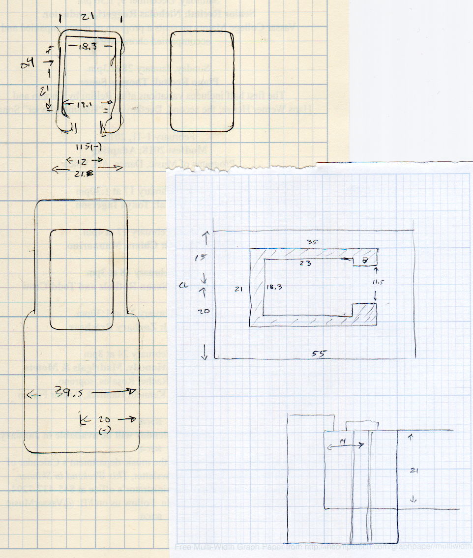
BarEndOut = [34.5,21.0]; // outside dimensions |
|
BarEndIn = [28.0,18.0]; // … inside |
|
BarEndSlot = [2.8,11.5]; // slot on open side |
|
BarEndRadius = 1.5; // corner rounding |
|
NumSides = 3*4; // … and sides |
|
|
|
BarHeightOC = 22.0; // min height above bench |
|
|
|
Clearance = 0.2; // overall bar clearance |
|
|
|
PinOffset = [14.0,2.5]; // clamp hardware pin location |
|
PinOD = 6.5; // … pin OD |
|
|
|
WallThick = 5.0; // basic wall & floor thickness |
|
|
|
EndBlockSize = [2*PinOffset.x + WallThick,BarEndOut.x + 2*WallThick,BarHeightOC + BarEndOut.y/2]; |
|
|
|
ScrewBlockSize = [2*PinOffset.x,BarEndOut.x + 2*WallThick,BarHeightOC + BarEndOut.y/2]; |
|
|
|
|
|
//—– |
|
// Define shapes |
|
|
|
// Aluminum bar extrusion |
|
|
|
module BarEnd(Length = 2.0,Hollow=true) { |
|
|
|
linear_extrude(height=Length,convexity=3) |
|
offset(delta=Clearance) |
|
difference() { |
|
hull() |
|
for (i=[-1,1], j=[-1,1]) |
|
translate([i*(BarEndOut.x/2 – BarEndRadius),j*(BarEndOut.y/2 – BarEndRadius)]) |
|
circle(r=BarEndRadius,$fn=3*4); // not related to block corner rounding |
|
if (Hollow) { |
|
translate([BarEndOut.x/2 – BarEndIn.x/2 – BarEndSlot.x,0]) |
|
square(BarEndIn,center=true); |
|
translate([BarEndOut.x/2,0]) |
|
square([BarEndOut.x,BarEndSlot.y],center=true); |
|
} |
|
} |
|
} |
|
|
|
// Block supporting open end of Bar |
|
|
|
module EndBlock() { |
|
|
|
Normal = (Chirality == "Left") ? [0,0,0] : [0,1,0]; |
|
Radius = WallThick; |
|
|
|
mirror(Normal) |
|
difference() { |
|
if (true) |
|
hull() { |
|
dx = EndBlockSize.x/2 – Radius; |
|
dy = EndBlockSize.y/2 – Radius; |
|
for (i=[-1,1],j=[-1,1]) |
|
translate([i*dx,j*dy,EndBlockSize.z – Radius]) { |
|
sphere(r=Radius,$fn=NumSides); |
|
cylinder(r=Radius,h=Protrusion,$fn=NumSides); |
|
} |
|
for (i=[-1,1],j=[-1,1]) |
|
translate([i*dx,j*dy,0]) |
|
cylinder(r=Radius,h=Protrusion,$fn=NumSides); |
|
} |
|
else |
|
translate([-EndBlockSize.x/2,-EndBlockSize.y/2,0]) |
|
cube(EndBlockSize,center=false); |
|
translate([EndBlockSize.x/2 – PinOffset.x,0*PinOffset.y,-Protrusion]) |
|
rotate(180/8) |
|
PolyCyl(PinOD,2*EndBlockSize.z,8); |
|
translate([EndBlockSize.x/2 – 2*PinOffset.x,0,BarHeightOC]) |
|
rotate([0,90,0]) rotate(-90) |
|
BarEnd(Length=EndBlockSize.x); |
|
} |
|
} |
|
|
|
// Block supporting screw end of Bar |
|
// Ad-hoc chamfers to clear screw mount castings |
|
|
|
module ScrewBlock() { |
|
|
|
Normal = (Chirality == "Left") ? [0,0,0] : [0,1,0]; |
|
Radius = WallThick; |
|
|
|
mirror(Normal) |
|
difference() { |
|
if (true) |
|
hull() { |
|
dx = ScrewBlockSize.x/2 – Radius; |
|
dy = ScrewBlockSize.y/2 – Radius; |
|
for (i=[-1,1],j=[-1,1]) |
|
translate([i*dx,j*dy,ScrewBlockSize.z – Radius]) { |
|
sphere(r=Radius,$fn=NumSides); |
|
cylinder(r=Radius,h=Protrusion,$fn=NumSides); |
|
} |
|
for (i=[-1,1],j=[-1,1]) |
|
translate([i*dx,j*dy,0]) |
|
cylinder(r=Radius,h=Protrusion,$fn=NumSides); |
|
} |
|
else |
|
translate([0,0,ScrewBlockSize.z/2]) |
|
cube(ScrewBlockSize,center=true); |
|
translate([0,PinOffset.y,-Protrusion]) |
|
rotate(180/8) |
|
PolyCyl(PinOD,2*ScrewBlockSize.z,8); |
|
translate([-ScrewBlockSize.x/2 – Protrusion,0,BarHeightOC]) |
|
rotate([0,90,0]) rotate(-90) |
|
BarEnd(Length=ScrewBlockSize.x + 2*Protrusion,Hollow=false); |
|
for (i=[-1,1]) |
|
translate([i*ScrewBlockSize.x/2,ScrewBlockSize.y/2,ScrewBlockSize.z – Protrusion]) |
|
rotate(45) |
|
cube([sqrt(2)*WallThick,sqrt(2)*WallThick,2*ScrewBlockSize.z],center=true); |
|
} |
|
} |
|
|
|
|
|
//—– |
|
// Build things |
|
|
|
if (Layout == "BarEnd") |
|
BarEnd(); |
|
|
|
if (Layout == "EndBlock") |
|
EndBlock(); |
|
|
|
if (Layout == "ScrewBlock") |
|
ScrewBlock(); |
|
|
|
if (Layout == "Build") { |
|
translate([EndBlockSize.z/2,0.6*EndBlockSize.y,EndBlockSize.x/2]) |
|
rotate([0,-90,0]) |
|
EndBlock(); |
|
translate([0,-0.6*ScrewBlockSize.y,0]) |
|
ScrewBlock(); |
|
} |