Ed Nisley's Blog: Shop notes, electronics, firmware, machinery, 3D printing, laser cuttery, and curiosities. Contents: 100% human thinking, 0% AI slop.
After a year of fairly light use, the lens holder (and “attack ring”) of my J5-V2 flashlight worked loose and began to rattle. The ring holding the lens in place turned out to be finger-loose, but that wasn’t the entire problem, so I removed it and looked inside:
The aluminum ring holding the LED assembly in place was also finger-loose, so I unwound it to take the whole front end apart:
J5-V2 Flashlight – front parts
Reassembly with a few dabs of Loctite in appropriate places should prevent future rattles.
Given the number of … issues … accompanying this thing, I’d say it’s not been a good cost performer. The Anker LC40 and LC90 flashlights work much better.
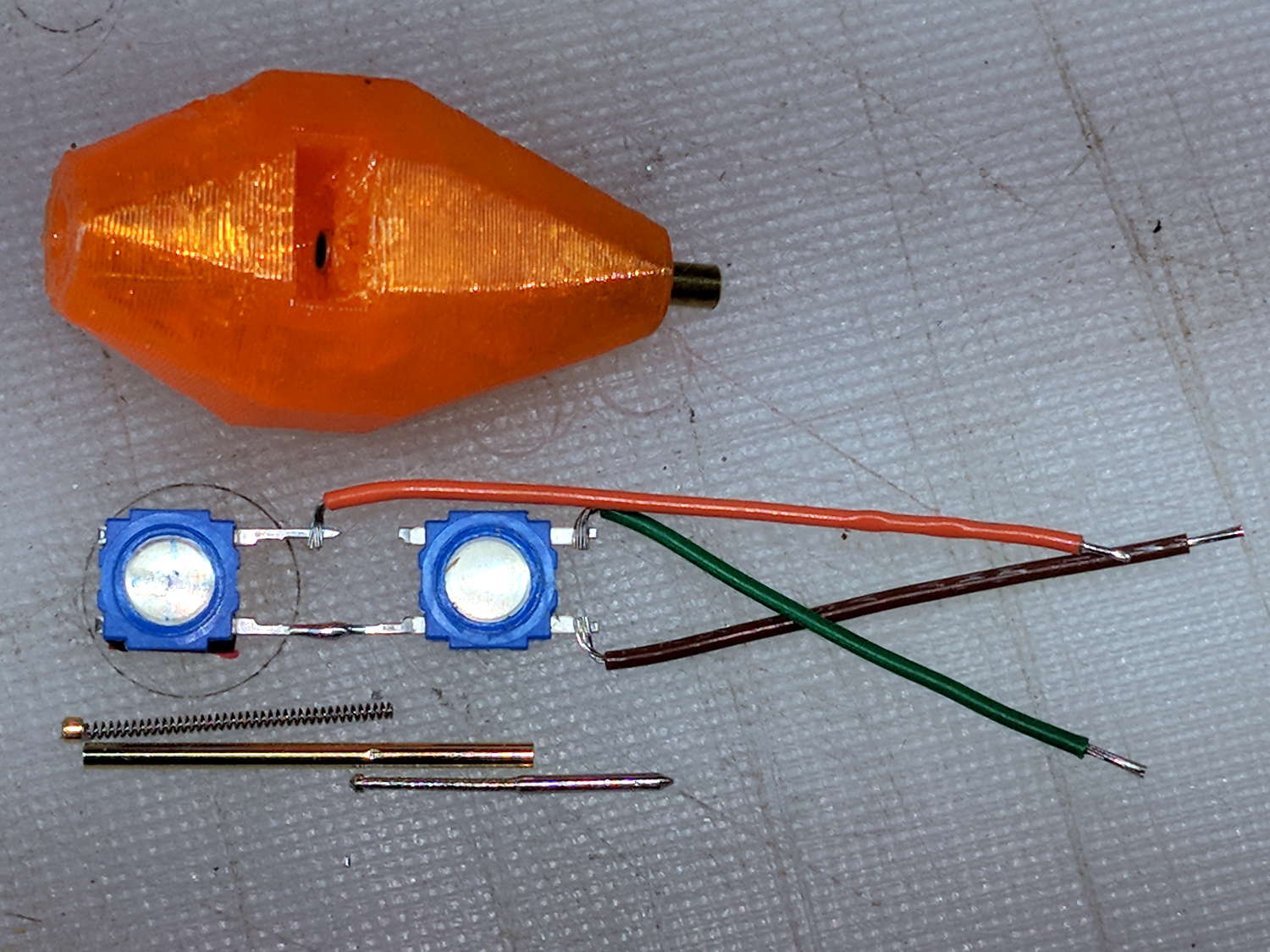
So I intended to shrink the Autolevel probe with 1/8 inch drill rod and a tactile membrane switch:
MPCNC – Simple Z probe – pogo tactile switch
Unfortunately, it didn’t work nearly as well as I expected, because the switch membrane requires slightly less than the 180 g of pressure that pushes the P100 pogo pin entirely into its housing, leaving no overtravel worth mentioning. The membrane switch mechanism itself has much less than 1 mm of overtravel after the dome snaps, which left me with an uncomfortable feeling of impending doom.
I managed to figure that out before completely assembling the thing, saving me a bit of time.
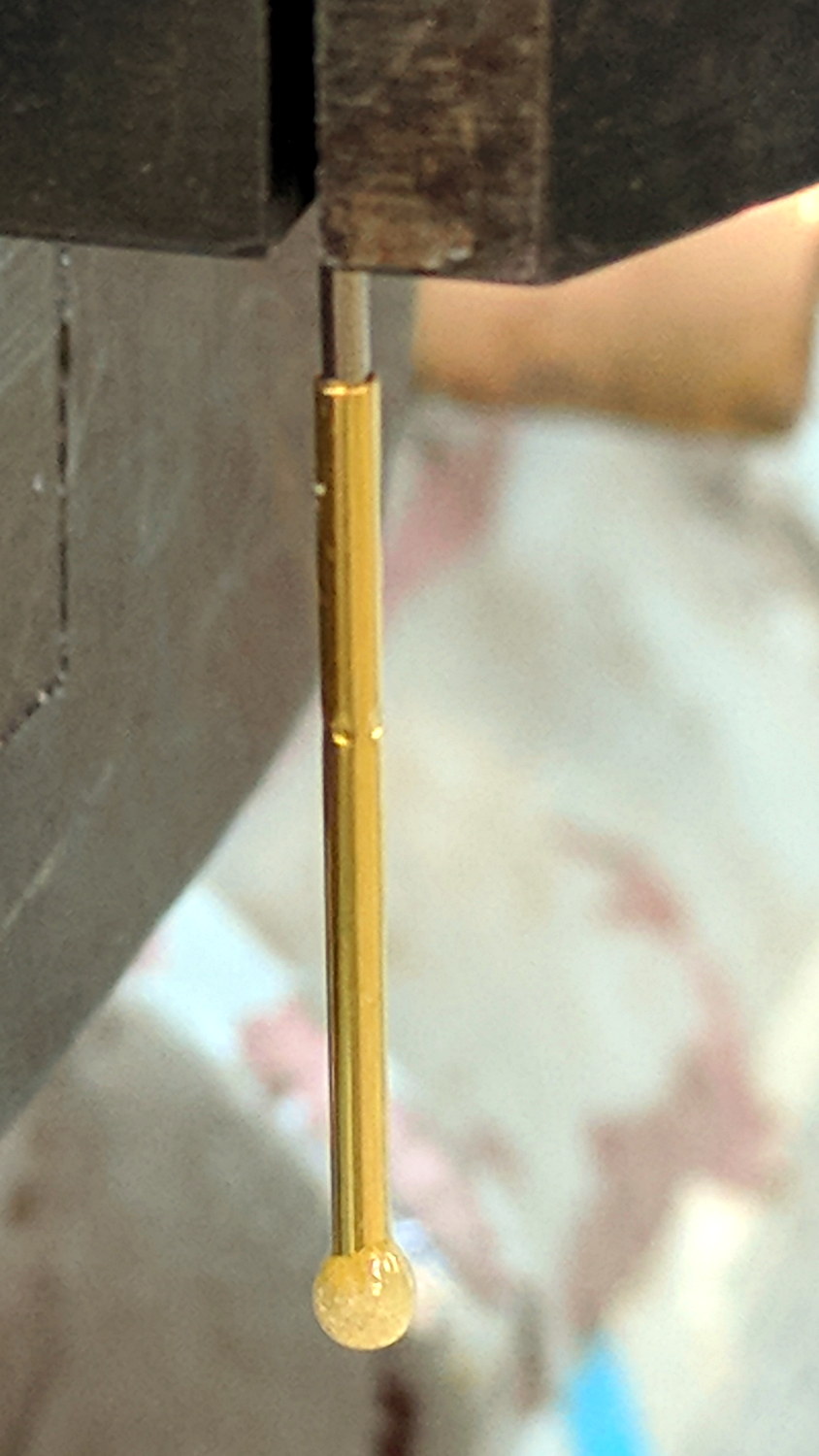
The end of the pogo pin initially sported a dot of epoxy to spread the load over the switch dome:
Pogo pin with epoxy switch-pusher drop
I dismantled the pogo pin to see whether I could substitute a more forceful spring how it worked. As expected, a teeny spring drives the probe up against a trio of indentations in the brass housing. I didn’t expect the probe to have such an intricate shape, but it’s obvious in retrospect.
The OpenSCAD code for the housing required minimal tweakage from the larger version, so it’s not worth immortalizing.
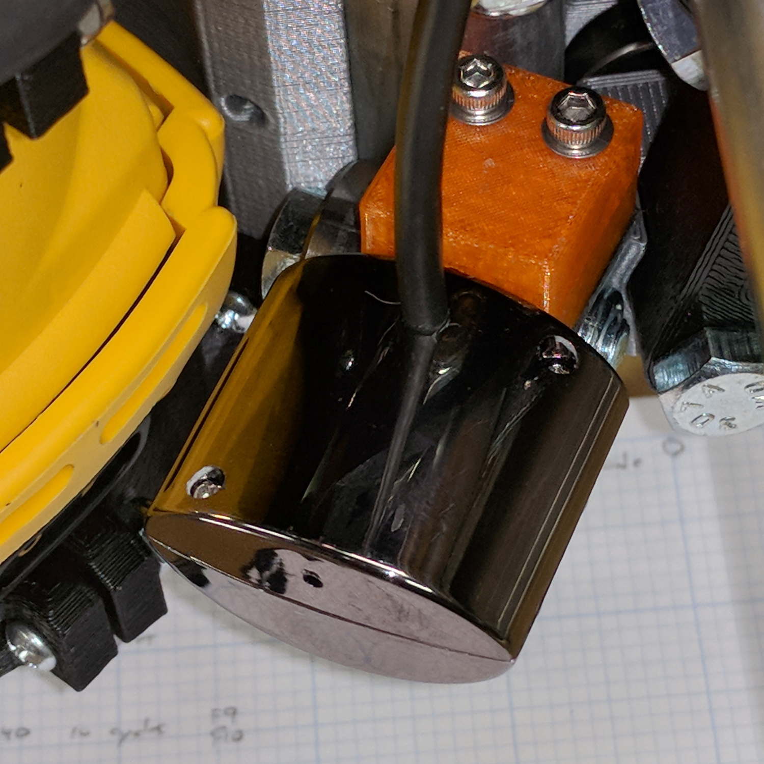
The bCNC doc shows a camera mount made from acrylic and aluminum, but the MPCNC tool carrier lacks anywhere to secure such a thing. The camera should be reasonably close to the spindle axis, high enough to clear the work, and stable enough to hold its alignment. There’s a tiny flat spot next to the outer-lower Z-axis bearing supports (along the bottom of the picture), so that’s where it must go:
MPCNC – Central Assembly – detail
At least for now, anyway.
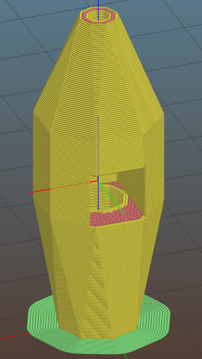
The USB camera originally mounted on a spring clip, with a 10 mm ball at the end of a 6 mm OD × 6 mm long stalk. Because we live in the future, building a matching ball socket isn’t particularly difficult:
MPCNC – USB Camera mount – Slic3r
3D printing FTW!
The stalk opening slants downward by 5°, because the camera PCB isn’t quite aligned with the stalk and I couldn’t get the first version to aim the lens directly downward.
A pair of brass inserts anchor the two M3 SHCS. The clamping force seems barely adequate to the task, but I’ll wait to see what else I don’t like before complexicating the situation.
The MPCNC bearing bracket doesn’t provide much surface area for the foam and it’s a bit more flexy than I’d like, but good practice probably requires verifying the spindle-to-camera offset before trusting the results, so we’ll see how it works.
The initial camera alignment consists of putting a mirror flat on the (pretty much level) platform:
MPCNC USB Camera – mirror alignment
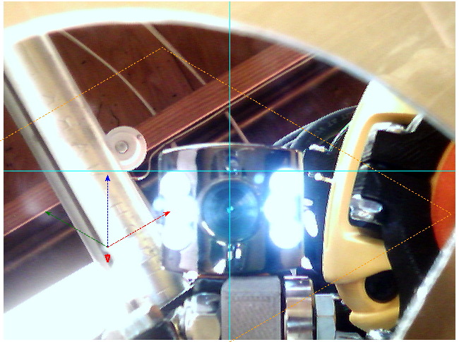
Then you adjust the camera so its lens looks squarely at itself in the middle of the image:
bCNC – Camera – Mirror Alignment – first mount
The picture shows the camera aligned left-to-right (because the ball can rotate around the shaft axis), but the first mount didn’t allow the stalk to have enough downward tilt to center the lens image on the horizontal crosshair, thus the -5° tilt appearing in the second version.
With the camera lens centered on its reflection, you know the optical axis is perpendicular to the mirror. Because the mirror is flat on the bench, the optical axis must be perpendicular to the bench, which is parallel to the XY plane. Because we assume the MPCNC Z-axis moves perpendicular to the bench = XY plane, the distance between the spindle axis and the camera axis will remain constant, regardless of the Z-axis position.
This file contains hidden or bidirectional Unicode text that may be interpreted or compiled differently than what appears below. To review, open the file in an editor that reveals hidden Unicode characters.
Learn more about bidirectional Unicode characters
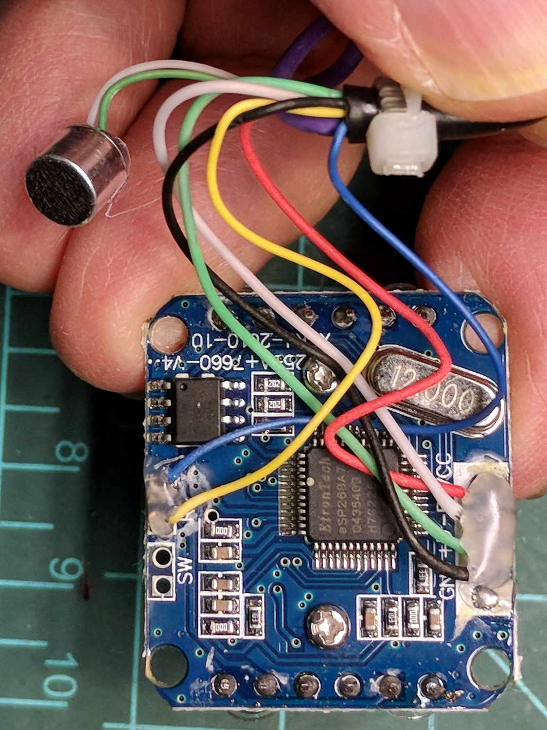
The bCNC doc shows how to use a USB camera for XY alignment and I want to try it out. The Box o’ USB Cameras emitted a likely candidate with a focusing lens, six (!) white LEDs, and a ball mount attached to an aggressive spring clip, but its thick USB cable included a lumpy brightness pot for the LEDs and sprouted a mic plug (apparently, it predated cheap USB audio):
USB Camera – OEM wiring
The Box o’ USB Cables emitted a surprisingly long cable amputated from some random hunk of consumer electronics.
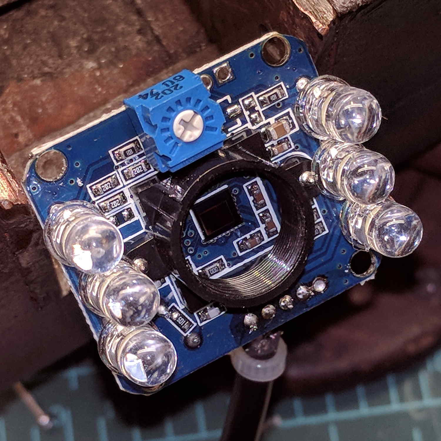
The LED brightness won’t need much adjustment after the first few minutes. I found a little 2 kΩ trimpot to fit the PCB holes:
USB Camera – inside – brightness pot
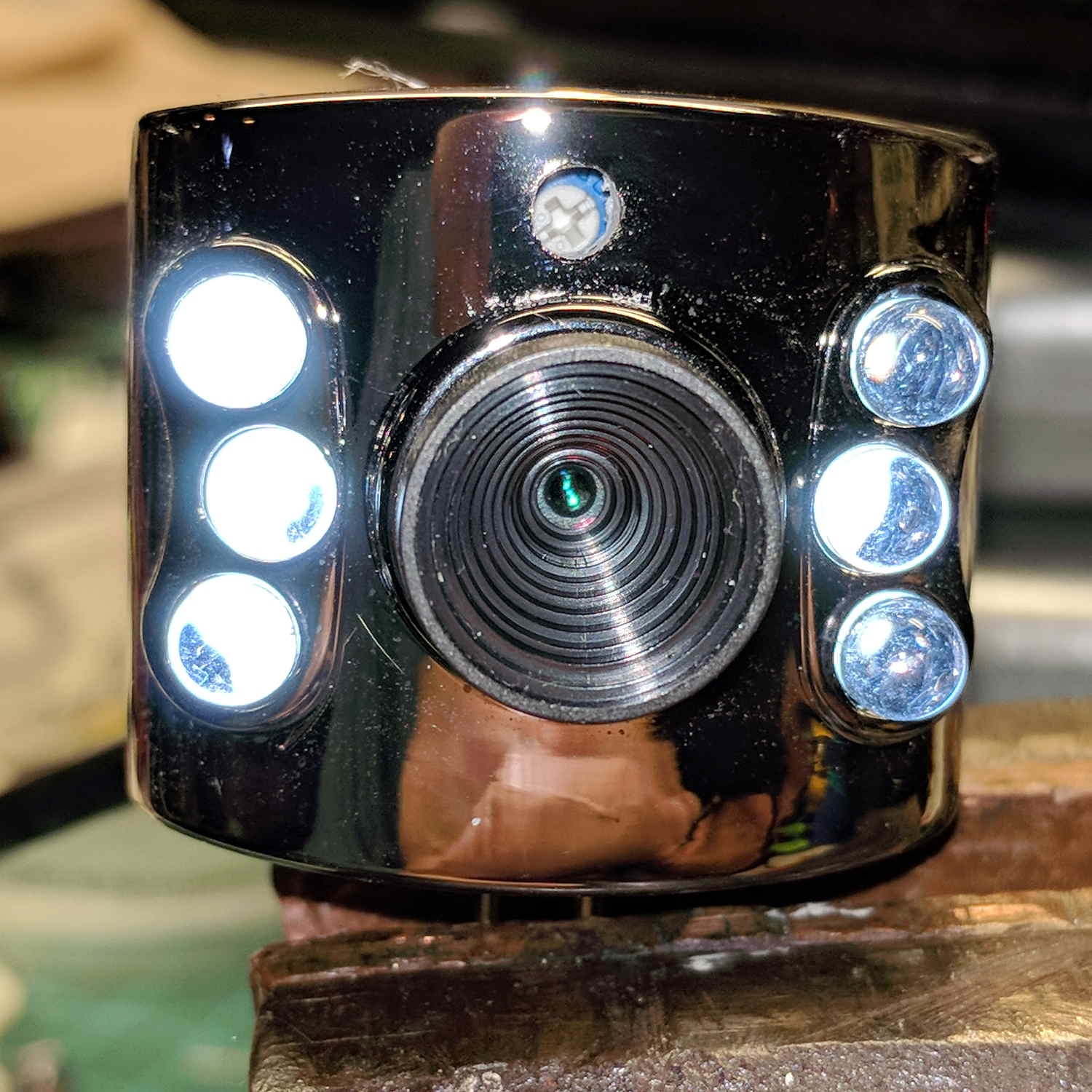
Miracle of miracles, the dial ended up almost centered behind the original mic pore. A few minutes of gentle filing embiggened the pore and moved it over the trimpot:
USB Camera – front with brightness pot
Yeah, the hole may need a plug or tape to keep the dust out, but there’s an even bigger gap around the lens.
It produces a 640×480 picture with pretty much the expected quality, which should suffice for its intended purpose.
Inside, it uses the same pushbutton and pogo pin as the pen holder design, with a similar brass tube around the pogo pin.
There’s a conspicuous lack of good wire management; we all know where those wires will snap. In practice, you’d secure it to the DW660 power cord, way up on top, to eliminate most of the flexing. Still, it wants better strain relief than its gets from those heatstink tubes.
It’s sitting upside-down in a 5 mm brim for more platform adhesion.
The next one will have a 1/8 inch stud to fit the DW660’s other collet and shorten the top by 3/8 inch, because I want the rod inserted three diameters for stability. The bottom can’t get much shorter, because the pogo pin determines the switch-to-tip distance. Maybe a simple membrane switch will work well enough?
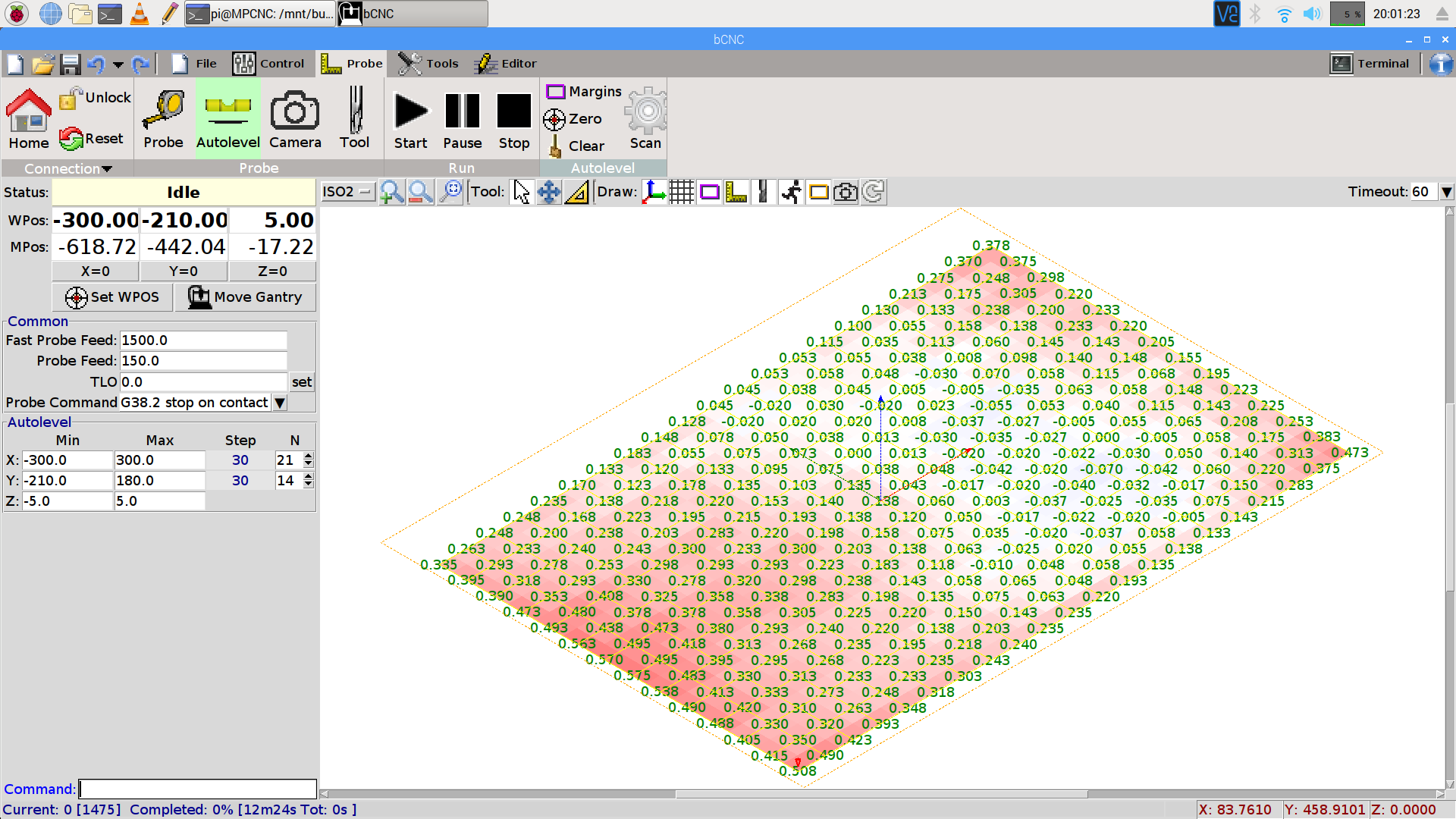
You can see the depression in the glass sheet pretty clearly in a bCNC Autolevel scan on 30 mm centers (clicky for more dots):
This file contains hidden or bidirectional Unicode text that may be interpreted or compiled differently than what appears below. To review, open the file in an editor that reveals hidden Unicode characters.
Learn more about bidirectional Unicode characters
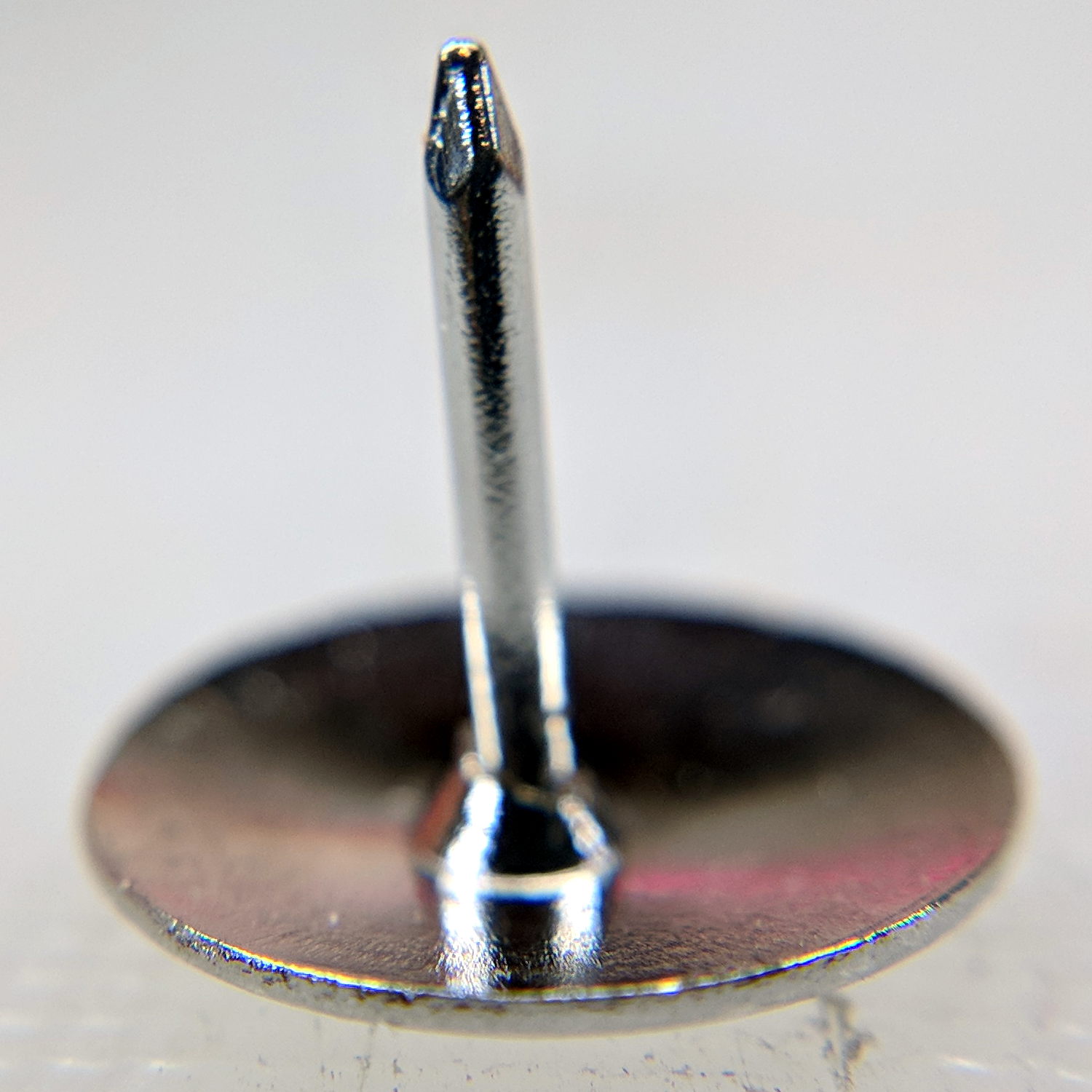
Mary mentioned the pivot pin supplied with a quilting ruler tended to hang up on the layers of fabric and batting in the quilt squares she’s been making. A quick look showed the pin bore a remarkable resemblance to an ordinary thumb tack:
Ruler Quilting Pivot Pin – as delivered
I reset the pin shaft perpendicular to the head, grabbed a small brass tube in the lathe tailstock, inserted pin in tube, grabbed the head in the chuck, ignored a slight radial offset, and attacked the pin with fine files and sandpaper:
Ruler Quilting Pivot Pin – sharpened
The lathe chuck seemed the easiest way to firmly hold the head; I rotated the chuck by hand while filing.
Most of the remaining scratches go mostly parallel to the pin, but it really didn’t work much better than before. We decided polishing the pin wouldn’t improve the situation enough to make it worthwhile.
That’s the difference between sharp and keen, which cropped up with the cheap ceramic knife from a while ago. The point may penetrate the fabric, but the shaft can’t get through the tight weave.
She’s now using a scary thin and pointy embroidery pin, having successfully rebuffed my offer to mount it in a suitable base.
The neighborhood raccoons made off with our steel-cage suet feeder, leaving a dangling chain, several puzzled woodpeckers, and a potential gap in Mary’s FeederWatch data. A quick Thingiverse search turned up a likely candidate and a few hours of 3D printing produced a replacement:
3D printed suet feeder
The cheerful party colors just sort of happened after I realized orange wasn’t the new steel.
I bandsawed the top plate from an acrylic sheet, rather than devote several hours to printing a simple disk with two slots. Said slots came from a bit of freehand work with the drill press, a step drill bit, and a nasty carbide milling bur(r).
The loops holding the chains won’t last for long, as hairy and red-bellied woodpeckers land with thump.
It hangs from the stub of a former ski pole, loosely secured to the bracket holding the former feeder, and extending another two feet over the abyss beyond the patio. I doubt the raccoons will remain daunted for long, but maybe they’ll catch a heart attack when it collapses.